

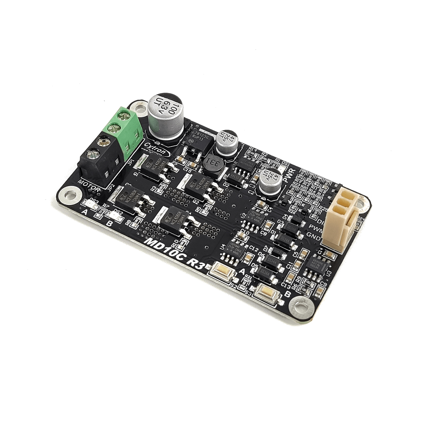


Cytron MD10C Single Channel DC Motor Driver 5V-30V 10Amp
The MD10C is a single-channel DC motor driver engineered to simplify connecting a microcontroller to a brushed DC motor. Housed on a compact PCB, the module groups power and motor terminals, visual LEDs and manual test buttons so users can quickly verify connections and behaviour without extra instruments. Its layout and clear silk-screen labeling make bench wiring and repeated assembly straightforward for hobby and classroom use.
Control is provided through simple logic inputs that accept common microcontroller signals, enabling both speed and direction control using PWM and a direction line. The board supports two common PWM modes so it can be used with different control strategies and firmware approaches. Because the inputs accept typical logic signals, integration with popular platforms and industrial controllers is painless.
The MD10C emphasizes practical usability: it uses solid-state switching for reliable, fast response and reduces mechanical wear compared with relay-based designs. Documentation and example projects accompany the product, making it ideal for prototyping, robotics labs and compact automation where a dependable, easy-to-wire motor driver is needed. Mounting holes and included spacers simplify board installation in enclosures and test rigs, speeding up build time for projects, and student projects too.

Features:
- Bi-directional control for one DC Brushed motor, single channel.
- Support motor voltage ranges from 5V to 30V.
- Maximum current up to 13A continuous and 30A peak (10 second).
- 3.3V, 5V, 12V and 24V logic level input, which support signal from Arduino,
Raspberry Pi, PLC and any controller that can produces PWM or logic signal
from 3.3V to 30V. - Solid state components provide faster response time and eliminate the wear
and tear of mechanical relay. - Full NMOS H-Bridge for better efficiency and no heat sink is required.
- Speed control PWM frequency up to 20KHz (output frequency is same as
input frequency). - Support both Locked-Antiphase and Sign-Magnitude PWM operation.
- The new MD10C should be powered from a single power source, the Vmotor
only. No additional Vin is required. - Support TTL PWM from microcontroller, not PWM from RC receiver.
- Dimension:75mm x 43mm.

Note: Rev 3.0 can support motor voltage range from 5V to 30V
Board Layout:
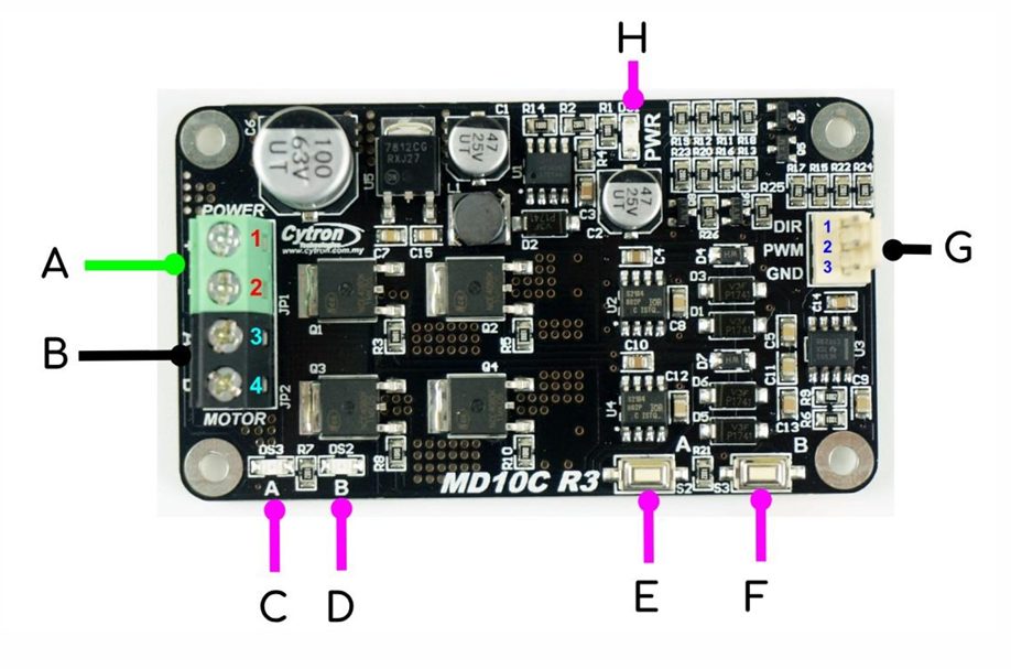
A. Terminal Block (GREEN): voltage polarity (Positive and Negative) is correctly connected
| Pin No. | Pin Name | Description |
|---|---|---|
| 1 | Vmotor Power + | Positive Supply (5V to 30VDC) |
| 2 | Vmotor Power – | Negative Supply or Ground terminal |
B. Terminal Block (Black) – Connect to DC brushed motor, or load.
| Pin No. | Pin Name | Description |
|---|---|---|
| 3 | Motor Output A | Connect to motor terminal A |
| 4 | Motor Output B | Connect to motor terminal B |
C. Red LED A: Turns on when the output A is high and output B is low. Indicates
the current flows from output A to B.
D. Red LED B: Turns on when the output A is low and output B is high. Indicates the current flows from output B to A.
E. Test Button A: When this button is pressed, current flows from output A to B
and motor will turn CW (or CCW depending on the motor connection).
F. Test Button B: When this button is pressed, current flows from output B to A
and motor will turn CCW (or CW depending on the connection).
G. Control Input Signal Pin:
| Pin No. | Pin Name | Description |
|---|---|---|
| 1 | GND | Logic ground |
| 2 | PWM | PWM input for speed control, supports up to 20 kHz |
| 3 | DIR | Direction control |
The truth table for the control logic is as follow:
| Pin 2 (PWM) | Pin 3 (DIR) | Output A | Output B | Operation |
|---|---|---|---|---|
| Low | X (Don’t care) | Low | Low | Brake (Low) |
| High | Low | High | Low | Forward |
| High | High | Low | High | Reverse |
H. Green LED: Power LED. Should be illuminate when the board is powered on.
Specifications:
| Parameters | Min | Typical | Max | Unit |
|---|---|---|---|---|
| Power Input Voltage: | 5 | – | 30 | V |
| I MAX (Maximum Continuous Motor Current): | – | – | 13 | A |
| I PEAK (Peak Motor Current): | – | – | 30 | A |
| V IOH (Logic Input – High Level): | 3 | – | 30 | V |
| V IOL (Logic Input – Low Level): | 0 | 0 | 0.5 | V |
| Maximum PWM Frequency: | – | – | 20 | kHz |
Dimension:

Applications:
- Small mobile robots.
- Educational robotics kits.
- Prototype motorized platforms.
- Conveyor and material handling modules.
- Motor test and diagnostic rigs.
- Automated hobby mechanisms.
- Lab and classroom motor experiments.
MD10C and SK40C as shown in the schematic:

Package Contents:
- 1x MD10C R3.0 10A DC Motor Driver
- 1x 2510 PCB Connector – 3 Ways (Female)
- 3x 2510 Terminal Pin
- 4x plastic spacer (7mm)
| Datasheet: | MD10C User’s Manual | ||
| Certificate: | UKCA-EMC Cert | UKCA RoHS | CE Cert |
| 3D CAD: | MD10C | ||
| Official Reseller: | Makers Electronics |