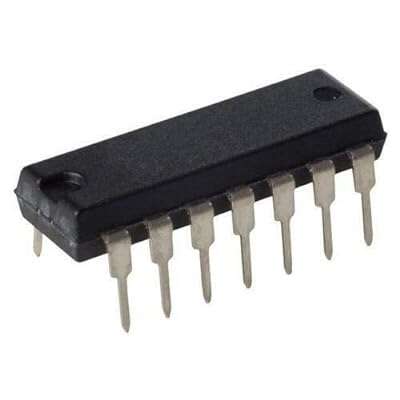
7433 2-Input Positive NOR Buffers with Open collector Outputs
The 7433 2-Input Positive NOR Buffers with Open collector Outputs is a logic gate IC featuring four independent 2-input positive-NOR buffers with open-collector outputs. These gates are designed to operate within a supply voltage range of 4.75V to 5.25V, making them suitable for TTL (Transistor-Transistor Logic) systems. The open-collector outputs require external pull-up resistors to function correctly and are ideal for wired-AND applications, where multiple outputs can be connected together to form a logical AND function.
Features:
- Four independent 2-input positive-NOR buffers.
- Open-collector outputs requiring external pull-up resistors.
- Supply voltage range: 4.75V to 5.25V.
- Input logic level: Low ≤ 0.8V, High ≥ 2V.
Specifications:
| Attribute | Value |
| Category | Logic ICs/Gates |
| Series | 74LSSeries |
| Low Level Range (VIL) | 0.8V |
| High Level Range (VIH) | 2V |
| Operating Temperature | 0℃~+70℃ |
| Quiescent Current (Max) | 3.6mA |
| Supply Voltage | 4.75V~5.25V |
| Number of Channels | 4 |
| Propagation Delay Time | 32ns@5V,45pF |
| Logic Gate Type | NORGate |
| Sink Current | 24mA |
Pin Configuration:

| Pin # | Type | Description |
|---|---|---|
| 1 | Output | Open-collector output from the first NOR gate. |
| 2 | Input | Input to the first NOR gate. |
| 3 | Input | Input to the first NOR gate. |
| 4 | Output | Open-collector output from the second NOR gate. |
| 5 | Input | Input to the second NOR gate. |
| 6 | Input | Input to the second NOR gate. |
| 7 | Power | Connect to ground (GND). |
| 8 | Input | Input to the third NOR gate. |
| 9 | Input | Input to the third NOR gate. |
| 10 | Output | Open-collector output from the third NOR gate. |
| 11 | Input | Input to the fourth NOR gate. |
| 12 | Input | Input to the fourth NOR gate. |
| 13 | Output | Open-collector output from the fourth NOR gate. |
| 14 | Power | Positive power supply (VCC). Connect to +5V power. |
Foot Print:

But not to worry – in this guide, you will learn all about this chip and how you can use its NOR gates in your circuit.
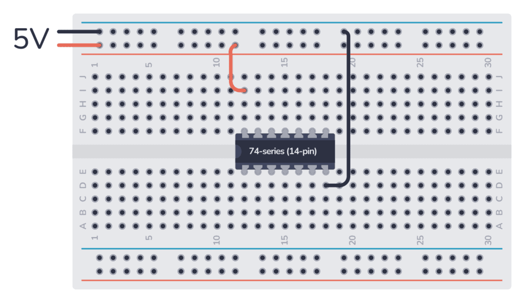
How To Use This Chip:
The 74HC33 comes in a 14-pin package, and you must connect its power before you can use it. Most ICs in the 7400 series support a VCC voltage of 5V. The main difference between the HC and LS version of the chip is that the 74HC33 supports 2V to 6V, while the 74LS33 only supports 5V.
Once it’s hooked up, you can use any of the four NOR gates inside.
This chip uses open-collector outputs which means you can only sink current, not source it (see How To Use Open-Collector Outputs below).
Each output of the 74HC33 can sink about 4 mA when powered with 5V. While the 74LS33 can usually sink about 8 mA of current. But these values can vary between manufacturers of the chip.
Applications:
- Wired-AND logic functions.
- Signal inversion in digital circuits.
- Interfacing with other logic families requiring open-collector outputs.
- General-purpose logic operations in TTL systems.