
ADC0808 8 Bit A/D Converter With 8-Channel Multiplexer DIP-28
ADC0808 8 Bit A/D Converter With 8-Channel Multiplexer DIP-28 is a CMOS data-acquisition device integrating an 8-bit successive-approximation analog-to-digital converter, an 8-channel single-ended analog multiplexer, and microprocessor-compatible control logic in one package. The internal architecture combines a 256‑step resistor ladder, a chopper‑stabilized comparator, and a successive-approximation register to provide accurate, monotonic conversion of analog input voltages into 8‑bit digital codes over a typical 0V to 5V range. This design eliminates the need for external zero or full‑scale adjustment in most applications, simplifying both design and calibration of measurement systems.
Features:
- Easy to interface with all Microprocessors or works Stand alone.
- Eight channel 8-bit ADC module
- Can measure up to 8 Analog values seamlessly
- On chip Clock not available, external Oscillator is needed (Clock)
- Digital output various from 0 to 255, Operating power is 15mW, conversion time 100us
- When Vref = 5V, for every 19.53mV of analog value there will be rise of one bit on digital side (Step size)
- Available in 28-pin PDIP package
Specifications:
| Parameter | Value |
|---|---|
| Resolution | 8Bits |
| Total Unadjusted Error | ±1/2LSB |
| Supply Voltage | 5VDC |
| Input Voltage Range | 0V to 5V |
| Clock Frequency | 640kHz |
| Conversion Time | 100µs |
| Power Consumption | 15mW |
| Operating Temperature | -40°C to 85°C |
| Package Type | DIP-28 |
ADC0808 8-Bit A/D Converter With 8-Channel Multiplexer:

ADC0808 Pin Configuration:
| Pin Number | Pin Name | Description |
| 1 to 5, 27, 28 | Analog Channel 1 to 5 | These 7 pins are the input pins for Analog voltage(sensor) |
| 6 | START | This is an input pin which is made high to start conversion |
| 7 | End of Conversion (EOC) | This is an output pin which goes high once the conversion is over |
| 8,14,15,18,19,20,21 | Output (2-1 to 2-7) | Output digital pins which gives the result of the ADC conversion |
| 9 | OUT EN | Has to be made high to get output on output pins |
| 10 | CLOCK | Has to be given clock signals (0V-5V) 20Mhz approx. |
| 11 | Vcc | Powers the IC typically with 5V |
| 12 | V ref(+) | Reference voltage pin, typically +5V is used normally |
| 13 | Ground | Connect to ground of the circuit |
| 16 | Vref(-) | Vref is connected to ground normally |
| 22 | Address Latch Enable(ALE) | This pin is should be temporarily made high to select ADC channel |
| 23,24,25 | ADD A, ADD B, ADD C | These three pins are used to select the channel |
Note: Complete Technical Details can be found at the ADC0808 datasheet given at the end of this page.
Where to use a ADC0808:
The ADC0808 IC is a commonly used ADC module for projects were an external ADC is required. It is a 28-pin Eight channel 8-bit ADC module. Meaning it can measure up to eight ADC value from 0V to 5V and the precision when voltage reference (Vref –pin 9) is +5V is 19.53mV (Step size). That is for every increase of 19.53mV on input side there will be an increase of 1 bit at the output side.
This IC is very Ideal to use with Microprocessors like Raspberry Pi, Beagle bone etc.. Or even to use as a standalone ADC module. Every ADC module requires a clock to function; this IC requires an external clock pulse to work. Hence, if you are looking for a ADC module with a decent resolution of 8-bit that could measure up to 8 channels then this IC is for you.
How to use ADC0808:
Since the ADC0808 IC can measure up to eight Analog voltage and also does not have an internal clock slightly requires more components to make it work compared to its predecessor ADC0804. The IC can be powered by +5V. The Vref + and the Output enable should also be supplied +5V to obtained the output. Powering the V ref + with +5V will make the IC operate with a step size of 19.53mV. The external clock should be connected to clock pin, this can either be a oscillator circuit or can just be an pulse generated from a MCU/MPU.
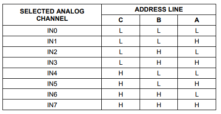
The right input analog voltage can be given to pins from IN1 to IN7, but the IC can read the voltage of only one channel at a time. This channel selection can be done with the pins ADD A, ADD B and ADD C. These three bits have to be set as shown in the table below to access the respective analog channel. Once the channel is set it should be enabled by making the Address latch enabled (ALE) pin to go high momentarily.
The digital output will be obtained from the pins 2-1 (OUT 1) to 2-8 (OUT 8) and the analog voltage should be connected to V in(+) pin as shown in the circuit. Also note that another end of the voltage source (sensor/module) should also be grounded to the circuit for the ADC conversion to work. Now, for the ADC Conversion to start we have o make the START pin to go high as soon as the EOC pin goes high. This can either be done through program or we can simple connect the EOC pin with START pin as shown in the circuit below.
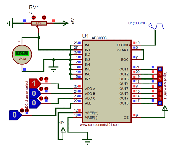
In the above circuit I have used a potentiometer to feed in a variable voltage of 0V to 5V to the IN1 pin and the present Voltage is read using a voltmeter. To read the voltage from channel one we have to set A=1 and B=0 and C=0 according to the table below, this can be done using a I/O pin of a MPU/MCU. As you can see in the image the voltage value is 2.15V and the resulting binary value is 01101110. Let us see how this binary value can be converted to Analog value, since we will need it while programming/designing.
Binary Value = 01101110
Converting to Decimal = (0*128)+(1*64)+(1*32)+(0*16)+(1*8)+(1*4)+(1*2)+(0*1)
= 110
Analog Voltage = Decimal Value * Step size
= 110 * 19.53mV
= 2.14V
The obtained value is 2.14V and the measured voltage is 2.15V which are very much close. So this is how you use an ADC0808 IC.
Applications:
- Operates With Any 8-Bit (µP) Processors or as a Stand-Alone Device
- Can measure up to eight channel hence can be used for complex projects
- Available in smaller packages for its performance, hence used in portable electronics.
- Widely used with Raspberry Pi, Beagle Bone and other MPU development platforms
- Interface to Temp Sensors, Voltage Sources, and Transducers
Reviews
There are no reviews yet.