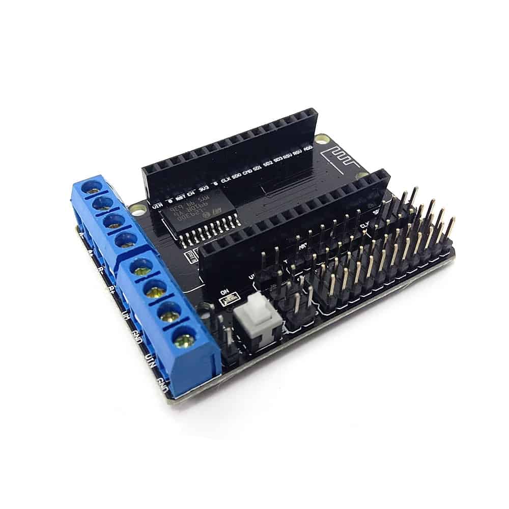
L293D Shield for NodeMCU ESP8266
The L293D Shield for NodeMCU ESP8266 is built around the L293D dual H-bridge motor driver, a chip designed to drive inductive loads such as DC motors, stepper motors, relays, and solenoids. The driver provides up to 600mA output current per channel, with 1.2A peak capability, and includes enable control, internal clamp diodes, and a separate logic supply so low-voltage control and motor power can be handled more safely.
In practical NodeMCU projects, this shield is used as a plug-in motor interface for Wi-Fi controlled cars, robot platforms, and automation builds. The referenced NodeMCU motor shield log shows it driving two motors using GPIO-based speed and direction control, and the project resources around it include a Wi-Fi car and an incubator controller, which reflects how commonly this part is used for remote motor control and compact embedded robotics.
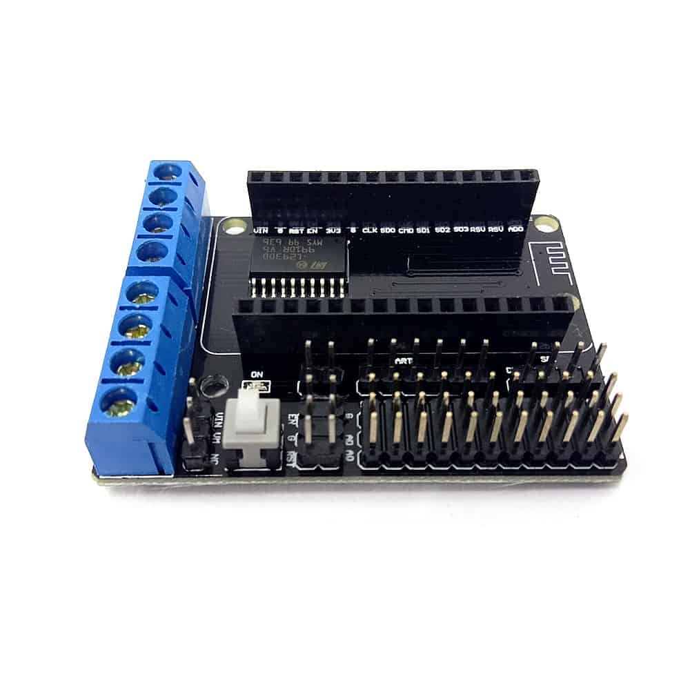
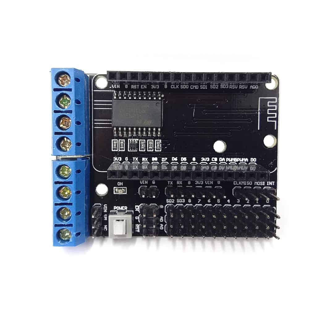
This shield is designed for the NodeMCU V2 (narrow width), it comes with an L293D motor driver and breaks the GPIO to headers for easy access when connecting to various sensor modules. With the L293D, this shield supports the control of two (2) brush motor, start, stop, brake, direction and also speed. The shield also extends the GPIO of NodeMCU to header pins in SVG sequence (RC servo alike), not to forget the UART, SPI, Power, and GND pins. There are options to power the board separately or with single power source. The board also comes with a power LED indicator and a latching push button as a power switch.
Features:
- Supports motor direction and speed control through NodeMCU GPIO.
- Can drive two DC motors independently.
- Uses the L293D H-bridge driver with built-in clamp diodes.
- Suitable for Wi-Fi robot cars and similar mobile projects.
- Compact shield-style board that stacks with NodeMCU.
- Offers separate logic and motor power handling.
Specifications:
| Symbol | Parameter | Test Conditions | Min. | Typ. | Max. | Unit |
|---|---|---|---|---|---|---|
| VS | Supply Voltage (pin 10) | VSS | 36 | V | ||
| VSS | Logic Supply Voltage (pin 20) | 4.5 | 36 | V | ||
| IS | Total Quiescent Supply Current (pin 10) | VI=L; IO=0; Ven=H | 2 | 6 | mA | |
| VI=H; IO=0; Ven=H | 16 | 24 | mA | |||
| Ven=L | 4 | mA | ||||
| ISS | Total Quiescent Logic Supply Current (pin 20) | VI=L; IO=0; Ven=H | 44 | 60 | mA | |
| VI=H; IO=0; Ven=H | 16 | 22 | mA | |||
| Ven=L | 16 | mA | ||||
| VIL | Input Low Voltage (pin 2, 9, 12, 19) | −0.3 | 1.5 | V | ||
| VIH | Input High Voltage (pin 2, 9, 12, 19) | VSS≤7 V | 2.3 | VSS | V | |
| VSS>7 V | 2.3 | 7 | V | |||
| IIL | Low Voltage Input Current (pin 2, 9, 12, 19) | VIL=1.5 V | −10 | μA | ||
| IIH | High Voltage Input Current (pin 2, 9, 12, 19) | 2.3V≤VIH≤VSS−0.6 V | 30 | 100 | μA | |
| VenL | Enable Low Voltage (pin 1, 11) | −0.3 | 1.5 | V | ||
| VenH | Enable High Voltage (pin 1, 11) | VSS≤7 V | 2.3 | VSS | V | |
| VSS>7 V | 2.3 | 7 | V | |||
| IenL | Low Voltage Enable Current (pin 1, 11) | VenL=1.5 V | μA | |||
| IenH | High Voltage Enable Current (pin 1, 11) | 2.3 V≤VenH≤VSS−0.6 V | ±10 | μA | ||
| VCE(sat)H | Source Output Saturation Voltage (pins 3, 8, 13, 18) | IO=−0.6 A | 1.4 | 1.8 | V | |
| VCE(sat)L | Sink Output Saturation Voltage (pins 3, 8, 13, 18) | IO=+0.6 A | 1.2 | 1.8 | V | |
| VF | Clamp Diode Forward Voltage | IO=600 nA | 1.3 | V | ||
| tr | Rise Time (*) | 0.1 to 0.9 VO | 250 | ns | ||
| tf | Fall Time (*) | 0.9 to 0.1 VO | 250 | ns | ||
| ton | Turn-on Delay (*) | 0.5 Vi to 0.5 VO | 750 | ns | ||
| toff | Turn-off Delay (*) | 0.5 Vi to 0.5 VO | 200 | ns |

Pinout:

| Pin No. | Name | Description |
|---|---|---|
| 1 | ENABLE 1 | Enable input for channels 1 & 2 (active high) |
| 2 | INPUT 1 | Input signal for output 1 |
| 3 | OUTPUT 1 | Output to motor/driver for channel 1 |
| 4 | GND | Ground |
| 5 | GND | Ground |
| 6 | GND | Ground |
| 7 | GND | Ground |
| 8 | OUTPUT 2 | Output to motor/driver for channel 2 |
| 9 | INPUT 2 | Input signal for output 2 |
| 10 | VS | Motor supply voltage (4.5V to 36V) |
| 11 | ENABLE 2 | Enable input for channels 3 & 4 (active high) |
| 12 | INPUT 3 | Input signal for output 3 |
| 13 | OUTPUT 3 | Output to motor/driver for channel 3 |
| 14 | GND | Ground |
| 15 | GND | Ground |
| 16 | GND | Ground |
| 17 | GND | Ground |
| 18 | OUTPUT 4 | Output to motor/driver for channel 4 |
| 19 | INPUT 4 | Input signal for output 4 |
| 20 | VSS | Logic supply voltage (4.5V to 36V) |
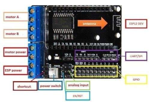
| Shield Label / Connector | NodeMCU Pin | GPIO | L293D IC Pin | Function / Notes |
|---|---|---|---|---|
| Motor A – DIRA | D3 | GPIO0 | Pin 2 (1A) | Direction control for Motor A (HIGH/LOW) |
| Motor A – PWMA | D1 | GPIO5 | Pin 7 (2A) | Speed control for Motor A (PWM) |
| Motor B – DIRB | D4 | GPIO2 | Pin 10 (3A) | Direction control for Motor B |
| Motor B – PWMB | D2 | GPIO4 | Pin 15 (4A) | Speed control for Motor B (PWM) |
| Motor A output | – | – | Pins 3 (1Y) & 6 (2Y) | Screw terminal for Motor A (two wires) |
| Motor B output | – | – | Pins 11 (3Y) & 14 (4Y) | Screw terminal for Motor B |
| Motor Power (motorpower) | – | – | Pin 8 (VS) | External power input for motors (4.5V–36V) |
| ESP Power (ESPpower) | VIN (or 5V) | – | Pin 16 (VSS) | Power for logic (from NodeMCU USB or VIN) |
| EN/RST | RST | – | – | NodeMCU reset button / enable line? (may connect to L293D enable pins 1 & 9 via jumper) |
| Shortcut | – | – | Pins 1 & 9 (EN1,2 & EN3,4) | Jumper to tie enables HIGH (always on) or connect to GPIO |
| Analog Input | A0 | ADC0 | – | Analog input pin (e.g., for battery voltage sensing) |
| GPIO breakout | Various (e.g., D0, D5-D8) | Various | – | Unused NodeMCU pins for sensors, I2C, etc. |
| UART/SPI | D5 (SCK), D6 (MISO), D7 (MOSI), D8 (CS) | GPIO14,12,13,15 | – | Breakout for SPI and UART communication |
| Power Switch | – | – | – | Switches motor power or logic supply |
| Antenna | – | – | – | ESP8266’s PCB antenna (on ESP12 module) |
Package Include:
- 1x L293D Shield for NodeMCU ESP8266.
Datasheet:
Resources:
- Simplest WiFi Car Using ESP8266 Motorshield, by Andriyf1 in Instructables
- NodeMCU Motor Shield, by Tony Kambourakis in Hackaday.io
Reviews
There are no reviews yet.