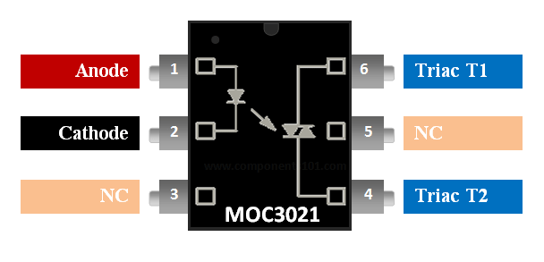
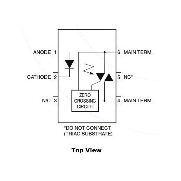
| Pin Number | Pin Name | Description |
| 1 | Anode (A) | Anode pin of the IR LED. Connected to logic input |
| 2 | Cathode (C) | Cathode pin of the IR LED |
| 3 | NC | No Connection – Cannot be used |
| 4 | Triac Main Terminal 1 | One end of the Triac which is present inside the IC |
| 5 | NC | No Connection – Cannot be used |
| 6 | Triac Main Terminal 2 | Other end of the Triac which is present inside the IC |
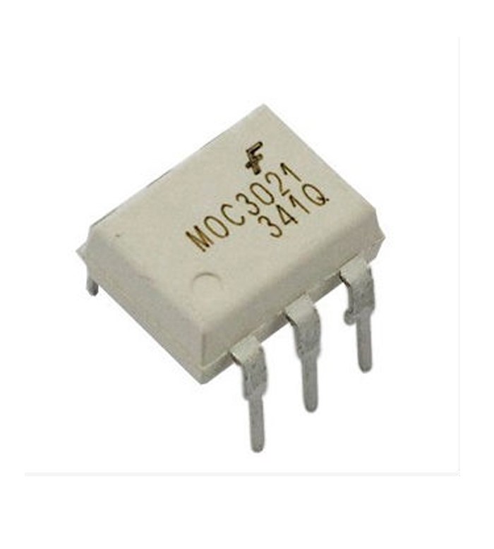
MOC3021 Features and Specifications
- Opto-isolator with Zero-Crossing Triac Driver
- Input LED Diode Forward Voltage: 1.15V
- LED Forward Latch Current: 15mA
- TRIAC output terminal voltage: 400V (max)
- TRIAC peak output current: 1A
- Available as 6-pin PDIP with and without M-suffix
Note: More details can be found at the MOC3021 datasheet which is available for download at the end of this page.
Where to use MOC3021 Phototransistor Optocoupler
The MOC3021 is a Zero-Crossing TRIAC driven Optocoupler or Optoisolator. As we know the term Optocoupler/optoisolater means the same that is we use light to indirectly couple to sets of circuits. The speciality of MOC3021 is that it has Zero-Crossing ability and is driven by a Triac.
Since the output is driven by a TRIAC we can drive loads upto 400V and the triac can conduct in both directions hence controlling AC loads will not be a problem. Also since it has zero-crossing ability, when the AC load is switched on for the first time the TRIAC will start conductiong only after the AC wave reaches 0V this way we can avoid direct peak voltages to the Load and thus preventing it from getting damaged. It also has a decent rise and fall time and hence can be used to control the output voltage.
This features of MOC3021 makes it an ideal choice for controlling high voltage AC loads through digital controllers like MPU/MCU. Since the output is controlled we can control the intensity of the light or the speed of a AC motor. So if you are looking for a opto-isolator to control a AC application through DC then this IC might be the right choice for you.
How to use MOC3021
The MOC3021 is normally used to control AC appliance, like brightness of a Bulb, speed of a motor etc. Either way, an opto-coupler will not be allowed to drive loads directly due to its limited current rating. They are normally connected to another power switch like a Triac in our case, this TRIAC will be able to provide enough current to drive the loads and will be controlled using the opto-coupler. A simple circuit diagram in which an AC bulb is controlled using a microcontroller is shown below.
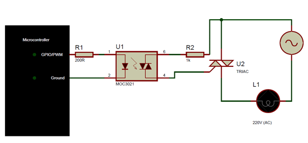
The MOC3021 can be used to switch loads by just turning the LED on or off, or we can also use PWM signals to switch the LED and thus the TRIAC. When we switch the TRIAC using PWM signals then the output voltage across the load can be controlled thus controlling the speed/brightness of the load.
When trying to switch AC loads it is important to understand the switching speed of the Opto-coupler. This switching speed depends in the amplitude of voltage that is being controlled by the TRIAC and the operating ambient temperature. The graph below will give you a good understanding of the time take.
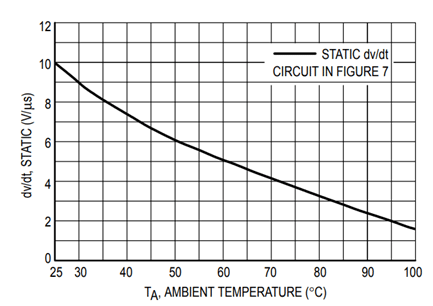
For example at 30 degree Celsius of ambient temperature the rate of change of voltage with respect to time will be 9V per unit time, where unit time is uS. So we can change 9V in one micro second.
Applications
- AC Light dimmers
- Strode lights
- AC motor speed control
- Noise coupling circuits
- Controlling AC loads using MCU/MPU
- Ac/DC Power control
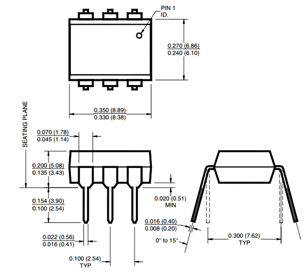
2D-Model





Reviews
There are no reviews yet.