

Description
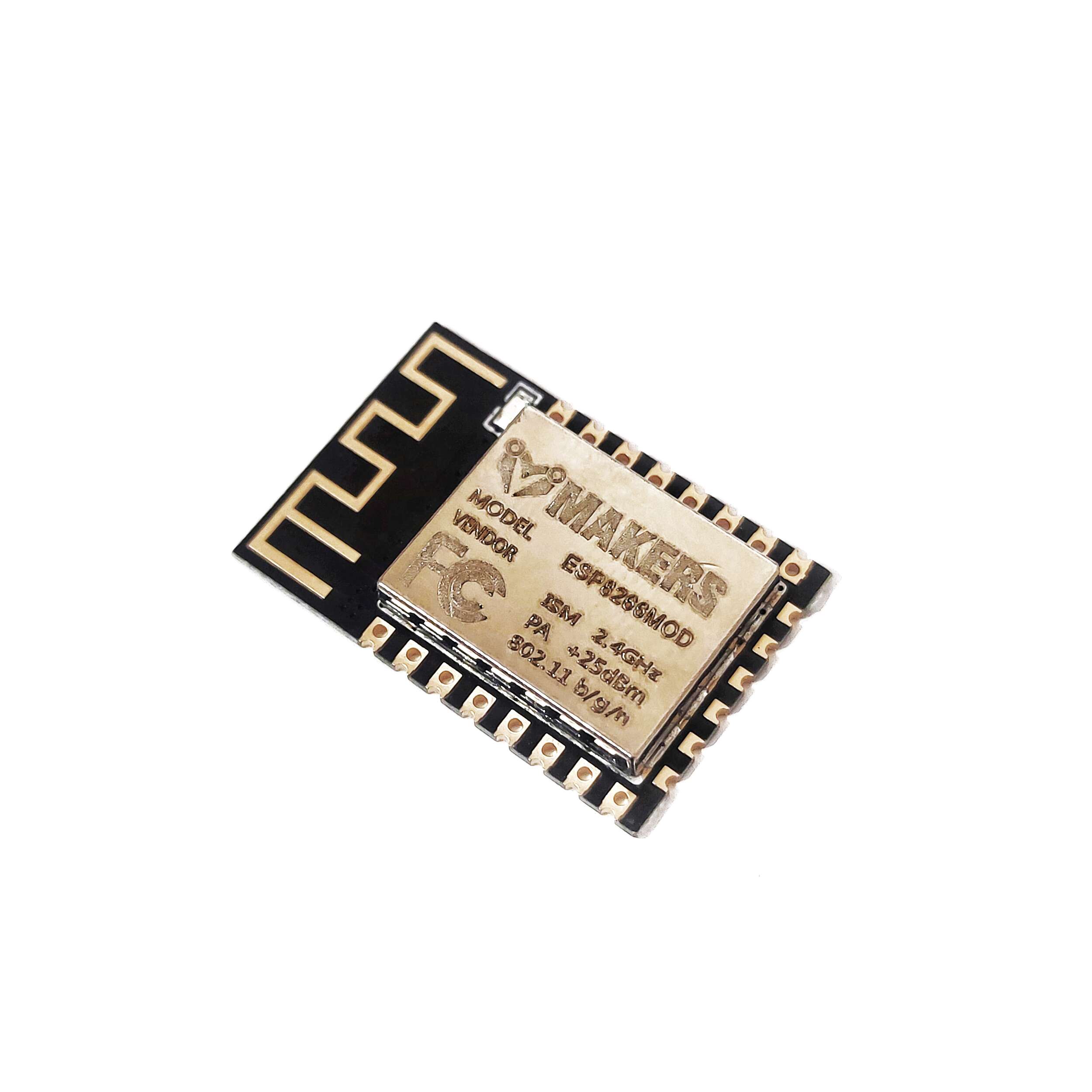
Wi-fi module based on the ESP8266 chip. Works in standard wi-fi 802.11 b/g/n at 2.4 GHz. Equipped with 22 leads – pitch 2 mm, of which 11 is GPIO, 1 ADC and SPI. Has a built-in LED and a PCB antenna. The plate size 24 x 16 mm.
The ESP8266 is a low-cost, high-performance wireless SOC that offers countless integration options for WiFi into other systems. Like Arduino, it can handle input and output, but its unique feature is that it includes Wi-Fi.
For the majority of “Internet of Things” projects, ESP is the greatest choice when compared to other Wi-Fi options on the market! It can also be included in complex projects because it is so inexpensive—and because of this. And the Arduino IDE is also compatible with ESP. If you’ve used Arduino before, utilizing ESP8266 will be simple for you to learn.
IoT projects frequently use Wi-Fi modules from the ESP family. However, there is some misunderstanding across ESP modules as a result of the quick update iteration speed and the absence of module-related information.
Differences between ESP12E and ESP12F
The “ESP-XX” series includes the ESP-12E. It is a tiny Wi-Fi module that connects a microcontroller or CPU to the wireless network. ESP8266EX serves as the ESP-12E’s brain. Using this module is relatively simple because it doesn’t include any complex circuits or programming.
The ESP-12F module belongs to the “ESP-XX” series, which combines a PCB antenna, 4MB of flash memory, and the ESP8266 microprocessor. The 12E has been upgraded into the ESP-12F. With improved stability and a stronger antenna, it is pin compatible.
The peripheral circuit, four lamination plate process, greater impedance matching, improved signal output, stability with anti-jamming capabilities, and PCB antenna after expert laboratory testing, flawless matching, and ROHS certification, have all been considerably improved in the ESP8266-12F! Based on the SPI and the new six IO ports, mouth extraction makes programming easier and expands the scope of application.
The ESP8266-12F chip’s global remote control feature accepts three commands.
The ESP-12F features a ground-breaking design, a redesigned four-layer board, improved RF performance in the revised antenna, and a 30%–50% improvement in communication distance over the ESP-12E!
Built-in PCB antenna, 4M bytes Flash, and semi-hole chip technology. The entire IO leads have a metal shielding shell and have received FCC, CE, and RoHS certifications.
Note: The only difference between the ESP-12E and ESP-12F is the antenna design; they are the same size and have the same pins. It is claimed that the antenna of the more recent ESP-12F is better optimized.
The ESP12F is a newer and more updated version of the ESP12E and features a better antenna design, hence the better output power.
Features of the module ESP-12F
Features that distinguish the ESP 12-F module on the background of the whole family of ESP-XX:
- Has 16 pins:
- 11 x GPIO – digital outputs/inputs
- 1 x ADC input – analog-to-digital converter
- 1 x SPI interface
- 1 x I2C interface
- 2 x UART (TX, RX) – for communicating, for example with Arduino
- Mounting: SMD / THT:
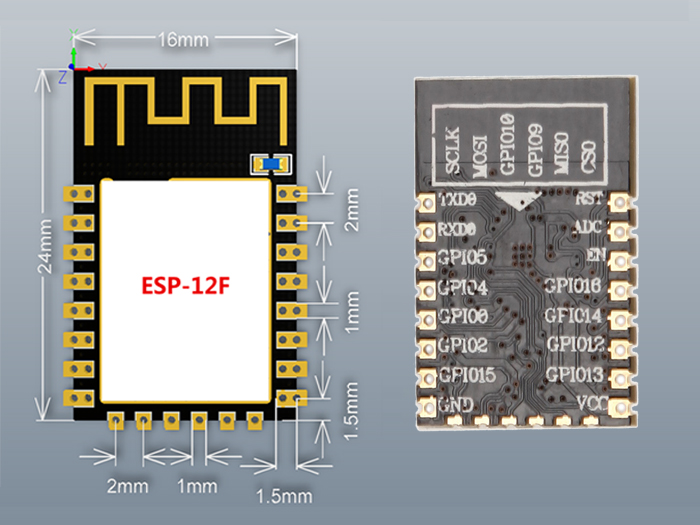
- Holes diameter: 0.9 mm
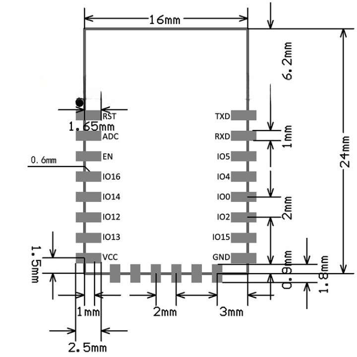
- Pitch of leads: 2 mm
- The default UART communication speed: 115200 bps
- Equipped with built-in PCB antenna
- Module shielded
- Dimensions: 24 x 16 mm
Connecting
The module has 22 leads, pitch of 2 mm.
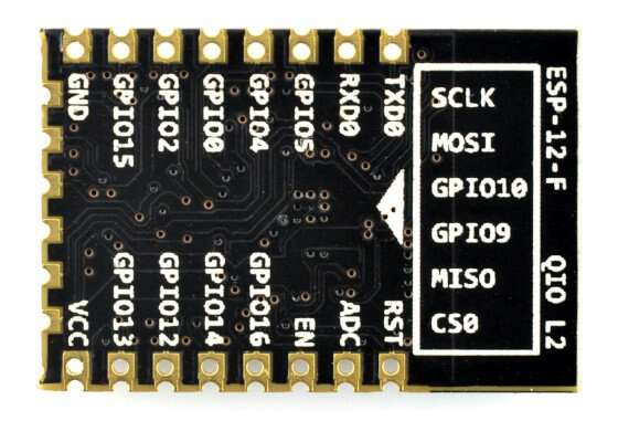
| PIN | DESCRIPTION |
|---|---|
| TxD | The transmitter of the serial interface UART. |
| RxD | The receiver of the serial interface UART. |
| GPIO x | Lead GPIO (digital output/ input) with a serial number. |
| GPIO 0 | GPIO with special function: To update, you need to indicate the low status (connect to GND). |
| GPIO 15 | GPIO No. 15 with a special function:
In normal and programming mode should indicate the low status (conect to GND). |
| ADC | Input of analog-to-digital converter. |
| REST | The system reset. |
| EN
(CH_PD) |
Power down – indication of low state causes a transition to sleep mode.To update, you need to indicate a high status (3.3 V). |
| VCC | The Power – 3.3 V. |
The product is compatible with ArduinoInstruction of connecting the module with Arduino basing on the module ESP-01. Tile tolerates a voltage of 3.3 V. Therefore, you must choose Arduino operating on voltage 3.3 V or use a converter. |
Specifications:
- Supply voltage: 3.3 V
- Current consumption at rest: approx. 10 mA
- Chip: ESP8266
- Flash memory: 4 MB
- Standard: wi-fi 802.11 b/g/n
- Operates in the 2.4 GHz frequency
- Supports WPA / WPA2 protections
- Can work in AP mode (Access Point), STA (standalone) and AP+STA
- Supports AT commands
- Communication: UART (Rx, Tx)
- The default UART speed: 115200 bps
- Mounting SMD or THT
- Pitch of leads: 2 mm
- Hole diameter: 0.9 mm
- Has 16 pitch leads 2 mm
- 11 x GPIO – digital outputs/inputs
- 1 x ADC input – analog-to-digital converter
- Equipped with communication interfaces: SPI, UART, SDIO
- Software support Lua
- Tile sizes: 24 x 16 mm
Reviews
There are no reviews yet.