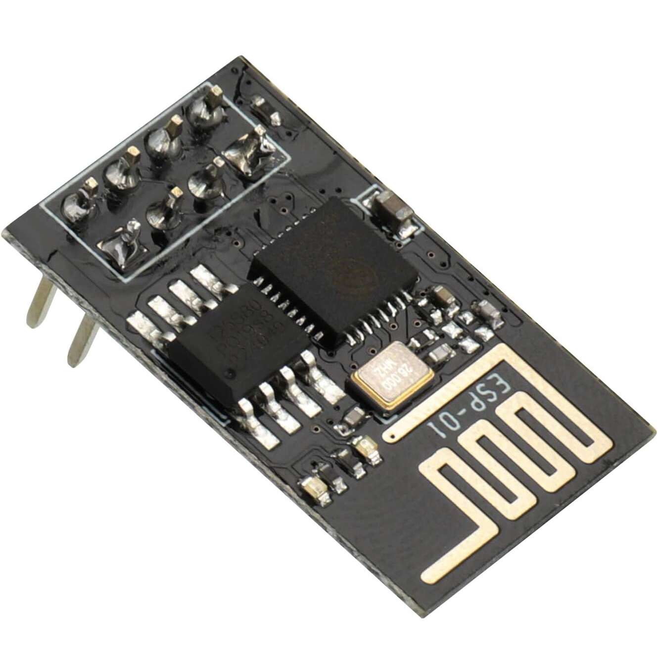
WiFi ESP8266-ESP01 Serial TTL Module
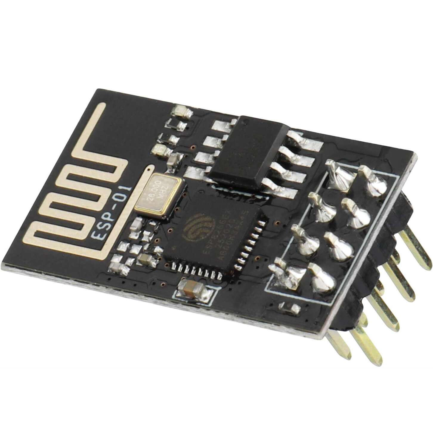
The ESP8266 ESP‑01 is a highly compact WiFi module that provides both serial‑to‑WiFi bridging and full standalone microcontroller operation. It employs a 32‑bit Tensilica Xtensa LX106 microprocessor running typically at 80 MHz (and supporting up to ~160 MHz) to deliver built‑in WiFi capabilities and integrated TCP/IP networking functionality.
Key Features of ESP8266 ESP-01 WIFI MODULE:
- 32‑bit Tensilica Xtensa LX106 processor core for onboard computing.
- WiFi IEEE 802.11 b/g/n connectivity and full TCP/IP stack support.
- 1 MByte (8 Mbit) external flash memory typical.
- Two GPIO pins exposed (GPIO0, GPIO2) for peripherals or external signalling.
- Serial UART interface (TX/RX) for communication or programming.
- Operates from 3.0‑3.6 V (nominal 3.3 V) power supply.
- Supports multiple operating modes: Station (STA), Access Point (AP), and combined AP+STA.
Specifications:
- Supply voltage: 3.3 V
- The working voltage of leads: 3.3 V
- Current consumption up to 300 mA
- Supports standard wi-fi – wi-fi 802.11 b, g, n
- Operates in the 2.4 GHz frequency
- Supports WPA / WPA2 protection
- Can work in AP mode (Access Point), STA (standalone) and AP+STA
- Transmitter power: 19,5 dBm
- Supports AT commands
- Has a built-in Flash memory: 1 MB
- Communication via the serial UART interface
- Has a built-in PCB antenna
- Equipped with communication interfaces: SPI, UART, SDIO
- Has 8 leads pitch of 2 mm
- 3 x GPIO – digital outputs/inputs
- Mounting: through the hole – pitch 2,54 (gold pin connectors)
- Dimensions: 24 x 14 mm
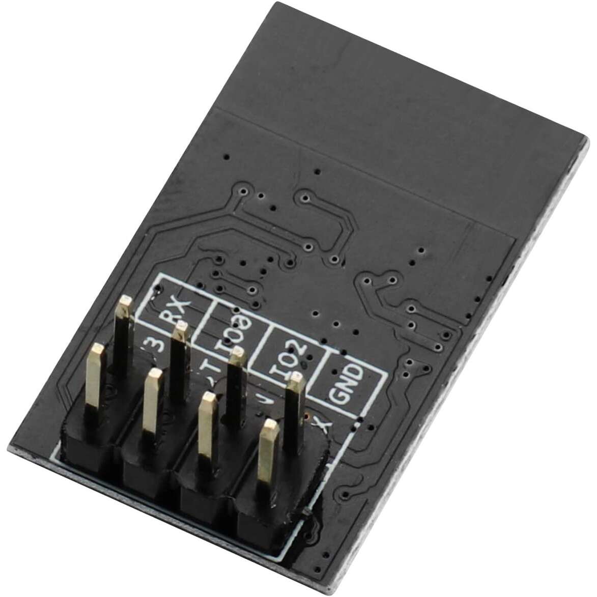
Pin Configuration:
The module has 8 pins output on the two-row (2×4) gold pin strip raster 2.54 mm.

| PIN | DESCRIPTION |
|---|---|
| Vcc | Power supply 3.3 V, current consumption up to 300 mA. |
| GND | The mass of the system. |
| Tx | The transmitter of the serial interface UART. |
| Rx | The receiver of the serial interface UART. |
| RST | Reset system – activated by low state. In a mode of regular operation, specify high state 3.3 V. |
| CH_PD | Power down – indicating low state causes a transition to sleep mode.
For software updates and communication via the UART, you must specify the high state 3.3 V. |
| GPIO0 | Lead GPIO number 0.
To update software, you must indicate the low status (connect to GND). |
| GPIO2 | Lead GPIO number 2. |
Applications:
- Add WiFi connectivity (serial‑to‑WiFi bridge) to microcontroller systems such as Arduino or STM32.
- Use as a standalone WiFi‑enabled microcontroller for IoT nodes, sensor hubs or home automation.
- Remote telemetry, data logging, wireless sensor networks and embedded control systems.
- Rapid prototyping of WiFi‑based devices, connecting to cloud or local networks.
- Educational projects and maker applications requiring low‑cost wireless connectivity.
Reviews
There are no reviews yet.