


Description
The LILYGO ESP32 T-Display-S3 Development Board is a powerful 32-bit 240MHz processor with a large 16MB Flash program memory. It incorporates a 1.9″ full color LCD, 2 user buttons and has WiFi and Bluetooth capability. It packs a lot of power and functionality in a very small package.
Key Features of LILYGO ESP32 T-DISPLAY DEVELOPMENT BOARD:
- Microcontroller: ESP32-S3R8 Dual-core LX7 32-bit
- Clock Speed: 240MHz
- USB Connector: USB-C
- Flash Memory: 16 MB
- RAM: 512Kb
- PSRAM: 8MB
- Display: 170 x 320 full color 1.9″ ST7789V TFT LCD. 8-bit parallel interface. Acrylic cover plate
- Digital I/O: 13
- PWM: 9 channels
- Analog Inputs: 10 channels, 12-bit
- Communications: Serial, SPI, I2C
- Connector Support: STEMMA QT / Qwiic JST-SH 1.0mm 4-pin
- Battery Voltage: GPIO04
- Integrated Sensors: IR remote, Hall sensor, temperature sensor, touch sensors, pulse counter, LNA
- Bluetooth: BLE 5 (Bluetooth Low Energy) + BT Mesh
- WiFi: 802.11 b/g/n 2.4GHz
- Buttons: 2 user programmable buttons GPIO0 and GPIO14 + Reset
- Programming: Compatible with Arduino IDE or Micropython
- Pin Spacing: 0.1″ pin to pin x 0.9″ row to row. Breadboard compatible with pins installed.
- Operating Voltage: 3.3V internal power and I/O.
- Power Source: 5V USB, 5V VIN pin, 3.7V lithium battery
The ESP32 based T-Display-S3 is a very flexible IOT board with significant processing power. It provides 16 MB of Flash memory for program space and runs at clock speeds of 240 MHz so has a fast processing speed. Because it incorporates an LCD for user feedback and has 2 buttons for user input, it can function as a complete little standalone system right out of the box simply by connecting it to a USB cable. Because of its WiFi and Bluetooth capabilities, it can also be used as a peripheral device in conjunction with another MCU just to provide WiFi, Bluetooth or other unique capabilities that it has.
With the pins installed, the 24-pin board is breadboard compatible and will leave one row of open contacts on each side of the board for making jumper connections. Be sure when using with a solderless breadboard to insert the T-Display-S3 into the breadboard by pressing on the pins and ends of the module and do not press directly on the LCD or damage could result. The USB end of the module with connectors on the bottom should overhang the end of the breadboard for clearance.
Display Characteristics
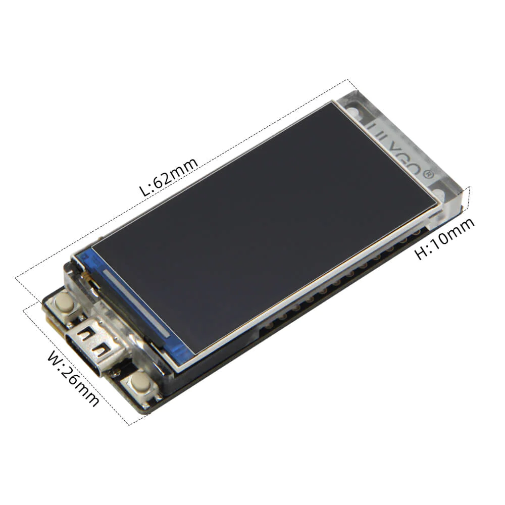
The display is a 1.9″ IPS TFT LCD with a resolution of 170 x 320. It has an acrylic mount to help support the display and provide a more integrated package than on the base T-Display module.
Unlike most displays, this one uses an 8-bit parallel bus, so it has the potential for very fast graphic updates. The pins used to drive the LCD are dedicated and are not brought out to the edge of the module.
The display uses the ST7789V driver and is supported by the TFT-eSPI library and is also compatible with the LVGL library.
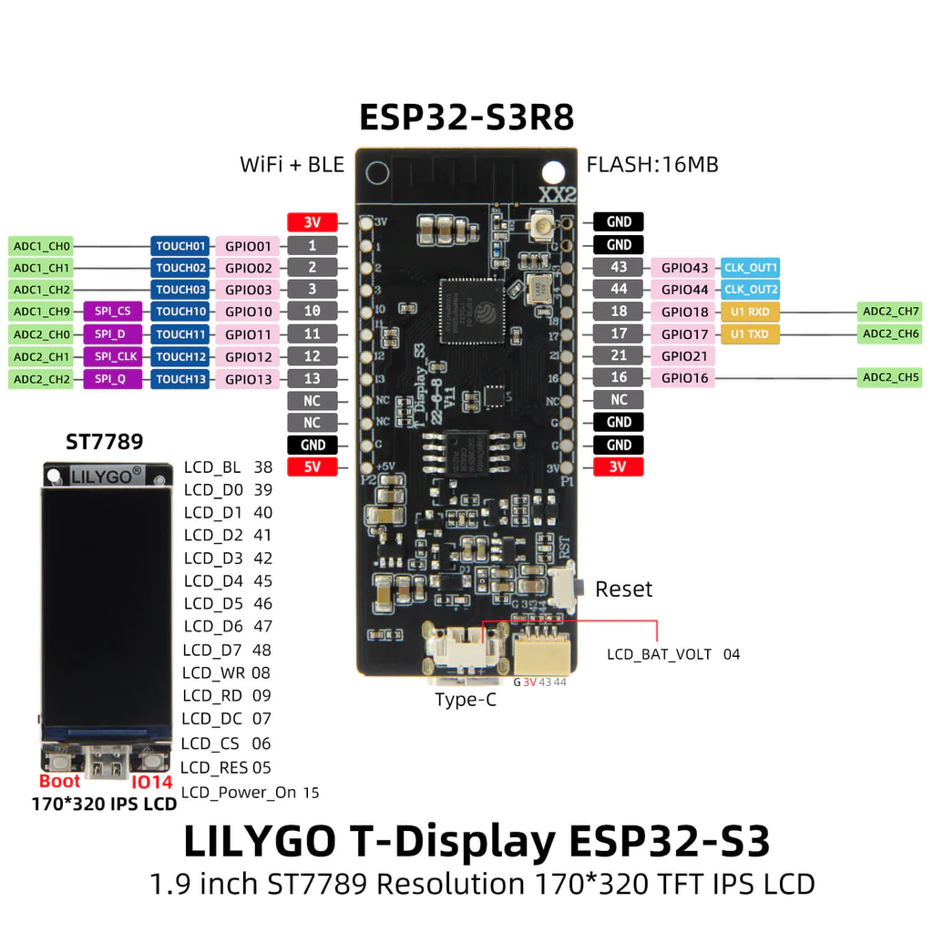
Pin Map for the T-Display-S3
One of the main limitations of the module for some applications is the relatively small number of I/O pins, but the ESP32 chip allows most of the I/O such as the serial ports, SPI and I2C to be multiplexed to any of the other GPIO pins for maximum flexibility.
This diagram shows how the pins are used on the T-Display-S3 module. Note that some pins are used internally for driving the LCD display and as inputs for two user buttons. Those pins are not brought out to the main header pins leaving 16 pins available for the user.

Digital I/O
There are 13 GPIO on the board that are brought out to the header pins. The pins are labeled GPIOx. When using with Arduino IDE, the digital pin number is the same as the GPIO pin number, so GPIO2 is referenced as just ‘2’.
All of the digital I/O support interrupts. In addition they can be configured to have pull-up or pull-down resistors. 9 of the pins support hardware PWM.
There are 3 pushbuttons included on the board. The two on top of the module are user programmable buttons on GPIO0 and GPIO14 which do not come out to the pins on the edge of the board. A third button on the side is a standard reset button that resets the ESP32 microprocessor.
Unlike some other development boards, the T-Display-S3 does not have a user controllable LED on any of its pins, but then again it has a complete display, so take that Arduino!
The digital I/O is limited to 3.3V. If using with 5V logic inputs, logic level translators must be used to prevent possible damage.
Analog I/O
Analog to Digital Converters
There are two 12-bit analog-to-digital converters (ADC1 / ADC2) on the ESP32. One or both of the A/D converters can be multiplexed across up to 10 input pins on this module. As with all the I/O pins, the analog inputs are limited to a voltage range of 0-3.3V. Higher voltages can damage the module
12-bit resolution provides readings in the range of 0-4095. The resolution of the A/D converters can be changed to a lower bit depth of 9-12 bits if desired. As with many high performance microcontrollers that have built in A/D converters on the same substrate, some amount of digital noise tends to get into the analog readings. Using a lower bit depth can help to reduce the impact of digital noise since the individual reading steps are larger.
Keep in mind that the A/D converters don’t have a completely linear behavior at the extreme ends of their range. If measuring a 0 to 3.3V voltage range, it may not be possible to differentiate between 0.0V and 0.1V or 3.2V and 3.3V so keep that in mind when interpreting the readings.
The ADC2 converter cannot be used when WiFi is also being used, in that case ADC1 should be used.
Internally GPIO4 is connected to the battery voltage and can be used to monitor the voltage level. It is connected via a divide by 2 resistor circuit, so the measured value will need to be multiplied by 2. When USB power is connected, this pin will measure the USB voltage, not the battery voltage.
Communication Buses
The module has the standard built-in buses and in many cases arbitrary GPIO pins can be assigned to those buses.
I2C
I2C is a common 2-wire bi-directional bus with a data line (SDA) and a clock line (SCL).
The default I2C is on GPIO 43 (SDA) and GPIO 44 (SCL) and these are available on the main pins as well as on the small STEMMA QT / Qwiic JST 4-pin connector along with 3.3V power and ground. These pins can also be repurposed to other functions such as serial TX/RX.

You can define the pins to use for I2C by using the command Wire. begin(SDA, SCL); where SDA and SCL are the pin numbers to use.
I2C requires pullup resistors to work properly. If the attached module does not have 2.2K – 4.7K pullups to 3.3V, they should be added to the SDA and SCL pins. 10K pullups may work OK for slower I2C communications.
WiFi / Bluetooth
As with all ESP32 processors, some level of WiFi and Bluetooth capability is included. The two functions are mutually exclusive e.g. you can use either one, but not both concurrently. You can however switch between them within the same application.
The Bluetooth is BLE 5 + BT mesh. BLE 5 (Bluetooth Low Energy) is a fairly new version of Bluetooth introduced in 2017. It is targeted toward low power applications like IoT. BT mesh refers to the ability to use Bluetooth in a mesh network with multiple nodes.
WiFi is the standard 802.11 b/g/n 2.4GHz. It uses the built-in PCB trace antenna by default. The module does have the capability to use an external antenna instead. It does require a small surface mount resistor to be moved to disconnect the PCB antenna and connect to the external antenna. The benefit of using an external antenna has not be evaluated.

Technical Specifications
| Microcontroller | ESP32-S3R8 Dual-core LX7 32-bit |
| Operating Voltage | 3.3V |
| Input Power | 5V or 3.7V Lithium Battery |
| Digital I/O Pins | 13 (4 input only) |
| PWM I/O Pins (Shared with Digital I/O) | 9 |
| Analog Input Pins | 10 (12-bit) |
| Analog Output Pins (DAC) | None |
| DC Current per I/O Pin | 10-40mA depending on total chip loading |
| Hardware Serial Ports (UARTS) | 1 or more |
| I2C Ports | 1 or more |
| SPI Ports | 1 or more |
| Touch Sensor Inputs | 7 |
| Flash Memory | 16 MBytes |
| ROM | 384 KBytes |
| SRAM | 512 KBytes |
| PSRAM | 8 MBytes |
| Clock Speed | 240MHz (default) |
| Network | 802.11 b/g/n 2.4GHz |
| Bluetooth | BLE 5 |
| USB Connector Style | USB Type-C Female |
| Board Dimensions (L x W x H) | 62 x 26mm x 10 (2.44 x 1.02 x 0.39″) |
| Pin Spacing (row-to-row) | 22.86mm (0.9″) |
| Country of Origin | China |
| Schematics (Down rev, shows CP2014 USB) | T-Display-S3 Schematic |
| ESP32 Datasheet T-Display uses ESP32-DOWDQ6 chip | ESP32-S3 |
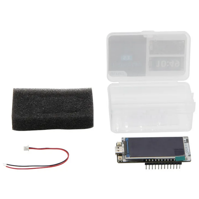
Package Includes:
- LILYGO ESP32 T-Display-S3
- Qty 2 – 1×12 male header pins
- JST 1.25mm 2-pin battery cable


Reviews
There are no reviews yet.