USB-to-TTL converters are widely used in electronics development, embedded systems, and hardware troubleshooting. They allow a computer to communicate with electronic devices that use a UART (Universal Asynchronous Receiver/Transmitter) serial interface, including microcontrollers, development boards, wireless modules, GPS receivers, and other embedded systems.
A computer typically communicates with peripherals through USB, while many microcontrollers exchange data through logic-level UART pins. A USB-to-TTL converter bridges these interfaces, allowing a computer to send and receive serial data without requiring the target circuit to include its own USB interface.
These converters are commonly used to upload firmware, monitor debugging messages, configure communication modules, test serial devices, and access embedded-system consoles. They are available in different forms, with different USB connectors, bridge ICs, logic-voltage options, and pin configurations.
Understanding how a USB-to-TTL converter works is important when choosing a suitable module and connecting it safely. In particular, users must distinguish between UART signal voltage and the converter’s power output, understand the TX and RX connections, and avoid confusing logic-level UART with RS-232.
This article explains the operating principle, internal components, pinout, voltage levels, technical specifications, practical connections, applications, and troubleshooting methods for USB-to-TTL converters.
2. What Is a USB-to-TTL Converter?
A USB-to-TTL converter is an interface device that connects a computer’s USB port to a target circuit’s logic-level UART interface.
It converts data between USB communication and asynchronous serial communication so that the computer and target device can exchange information.
A typical converter contains a USB-to-UART bridge integrated circuit and supporting components.
Depending on its design, it may also include a voltage regulator, USB connector, pin header, indicator LEDs, protection components, and optional control-signal connections.
Understanding USB, UART, and TTL
These terms describe different parts of the communication system:
USB (Universal Serial Bus): A standard interface used to connect computers and peripheral devices.
UART (Universal Asynchronous Receiver/Transmitter): A hardware interface that transmits and receives serial data without a separate shared clock signal.
TTL logic: A term commonly used to describe logic-level serial signals.
Many modules marketed as USB-to-TTL converters use 3.3V or 5V CMOS-compatible UART signaling rather than strict TTL electrical specifications.
The term USB-to-TTL is widely used in electronics retail and development, but the actual electrical characteristics of the UART pins depend on the bridge IC and the converter board’s circuit design.
USB-to-TTL Converter vs. USB-to-RS-232 Converter
These devices are not interchangeable.
Feature
USB-to-TTL Converter
USB-to-RS-232 Converter
Output interface
Logic-level UART
RS-232 serial interface
Signal voltage
Commonly 3.3 V or 5 V logic
Bipolar voltage levels defined by RS-232
Signal polarity
Conventional UART logic
Inverted relative to logic-level UART
Typical connection
Microcontroller UART pins
RS-232 serial equipment
Additional interface circuit
May require logic-level shifting
Uses an RS-232 transceiver
A true RS-232 port must not be connected directly to ordinary microcontroller UART pins.
An appropriate RS-232 transceiver is required to convert between RS-232 electrical signaling and logic-level UART.
3. How Does a USB-to-TTL Converter Work?
A USB-to-TTL converter operates as a communication bridge between the computer’s USB interface and the target device’s UART interface.
The USB-to-UART bridge IC handles the conversion between USB data and UART serial frames.
It also communicates with the computer through the appropriate USB driver.
Many converters appear to the operating system as a virtual COM port or serial device.
Main Operating Stages
USB connection: The converter connects to the computer through a USB port.
Device recognition: The operating system detects the USB bridge and loads the appropriate driver.
USB-to-UART conversion: Data received from the computer is converted into UART serial signals.
UART transmission: The converter sends data through its TXD pin to the target device’s RXD pin.
UART reception: Data arriving at the converter’s RXD pin is converted into USB data and transferred to the computer.
Understanding UART Communication
UART communication is asynchronous, meaning that the transmitter and receiver do not share a separate clock signal.
Instead, both devices use agreed communication settings to determine when each bit is transmitted and sampled.
The main settings include:
Baud rate.
Number of data bits.
Parity.
Number of stop bits.
A common configuration is 115200, 8-N-1, which means:
Baud rate: 115200 bits per second.
Data bits: 8.
Parity: None.
Stop bits: 1.
Both devices must use compatible settings for reliable communication.
UART Frame Structure
A typical UART frame contains the following elements:
Start bit: A LOW logic level indicating the beginning of a frame.
Data bits: The information being transmitted, commonly 8 bits, usually sent least significant bit first.
Parity bit: An optional bit used for basic error detection.
Stop bit or bits: A HIGH logic level marking the end of the frame.
When no data is being transmitted, a conventional UART TX line remains in the HIGH idle state.
Example: Calculating UART Transmission Time
For an 8-N-1 configuration, each transmitted byte requires 10 bits:
1 start bit.
8 data bits.
1 stop bit.
At a baud rate of 9600 bits per second, the approximate time required to transmit one byte is:
\[ t=\frac{10}{9600}=0.0010417\text{ s} \]
\[ t\approx1.04\text{ ms} \]
The theoretical byte transmission rate is:
\[ R=\frac{9600}{10}=960\text{ bytes/s} \]
This calculation excludes software delays and higher-level communication overhead.
It illustrates why the effective data throughput of UART is lower than the baud rate when framing bits are included.
4. Main Types of USB-to-TTL Converters
USB-to-TTL converters are available in different physical designs.
Although they perform the same basic USB-to-UART conversion, their connectors, pin arrangements, power options, and additional signals may differ.
USB-to-TTL Converter Modules
These are compact printed circuit boards with a USB connector on one side and a pin header on the other.
They are commonly used with breadboards, development boards, and custom microcontroller circuits.
Typical connections include:
VCC or power-output pins.
GND.
TXD.
RXD.
Optional DTR, RTS, CTS, or other control signals.
USB-to-TTL Converter Cables
These converters integrate the USB-to-UART circuit into a cable.
The device end may have individual wires, a connector, or a pin header.
They are useful for accessing UART consoles on embedded equipment, routers, and other devices.
However, wire colors and pin orders are not universal, so the cable’s documentation must be checked before connection.
Selectable-Voltage USB-to-TTL Modules
Some modules include a jumper or switch for selecting 3.3 V or 5 V operation.
This can make one converter suitable for different target systems.
However, the selector may affect only the UART signal levels, only the power output, or both, depending on the design.
Never assume that a 3.3 V/5 V label describes every pin on the module.
USB-to-TTL Modules with Control Signals
More advanced modules may expose additional UART control signals:
DTR (Data Terminal Ready): A control output that can be used for automatic reset on compatible development boards.
RTS (Request to Send): A control output used for hardware flow control or, in some designs, boot/reset circuits.
CTS (Clear to Send): An input used for hardware flow control.
DSR (Data Set Ready): An additional modem-control input.
These signals are not required for basic TX/RX communication, but they can be important for automatic firmware uploading and communication with equipment that uses hardware flow control.
Comparison of Converter Types
Converter Type
Main Features
Typical Applications
Basic USB-to-TTL module
USB connector and TX, RX, GND pins
Microcontroller communication
USB-to-TTL cable
Integrated converter and cable
Embedded serial consoles
Selectable-voltage module
3.3 V/5 V selection, depending on design
Different logic-voltage systems
Module with control pins
DTR, RTS, CTS, or other signals
Automatic reset and flow control
5. USB-to-TTL Converter Products at Makers Electronics Store
Makers Electronics Store lists several products relevant to USB-to-TTL and USB-to-UART communication.
The following products were identified on the store website during research.
Product stock and specifications may change, so check each listing before publication or purchase.
CP2102 USB 2.0 to TTL UART Serial Converter Module 5 Pin
This module uses a PL2303 USB-to-UART bridge IC and provides a serial interface for connecting a computer to a compatible TTL-level device. The store lists it for microcontroller-to-PC communication, programming, and debugging.
The listing identifies TXD, RXD, GND, 3.3 V, and 5 V connections. It also describes a 2.54 mm connector pitch, data-activity indicators, and a resettable fuse.
Specifications stated in the store listing:
Main IC: PL2303.
USB interface: USB 2.0 full-speed.
UART connections: TXD, RXD, GND.
Listed power connections: 3.3 V and 5 V.
Listed baud-rate range: 300 bps to 1.5 Mbps.
Additional features: Data indicators and resettable fuse.
Connector: USB Type-A and TTL pin header.
The product page contains older operating-system compatibility statements.
Check current driver support for the exact PL2303 version before using it with a modern computer.
This module uses the CH340G USB-to-serial bridge IC. The store describes a selectable 3.3 V/5 V logic-level arrangement using a jumper. It is intended for programming and serial communication with compatible microcontrollers and development boards.
The product listing also describes a reset button and a transparent protective cover. Confirm the module’s pinout and the exact function of its voltage selector before making connections.
This multifunction module uses a CP2102 USB-to-UART bridge and includes additional interface circuitry for several serial conversion modes.
According to the store listing, its supported modes include USB-to-TTL, USB-to-RS-232, USB-to-RS-485, TTL-to-RS-232, TTL-to-RS-485, and RS-232-to-RS-485.
The listing describes selectable 3.3V and 5V logic levels, onboard power outputs, TX/RX indicators, DTR/RTS signals, and resettable overcurrent protection.
Specifications stated in the store listing:
Main IC: CP2102.
Communication modes: USB, TTL, RS-232, and RS-485 conversion combinations.
Logic voltage: 3.3 V / 5 V compatible.
Power outputs: 3.3 V and 5 V.
Listed maximum baud rate: 1 Mbps.
Interface selection: DIP switches.
Board dimensions: 31 × 18 mm.
This is not simply a basic USB-to-TTL adapter.
Its additional transceiver circuits allow it to work with other serial electrical interfaces.
Follow the module’s switch settings and connection documentation for the selected mode.
Product descriptions and module revisions can differ.
Verify whether a 3.3 V/5 V selector changes the UART signal levels, the VCC output, or both.
The bridge IC’s datasheet does not necessarily describe the complete finished module.
6. USB-to-TTL Converter Pinout and Connections
Correct wiring is essential for reliable UART communication. Most basic USB-to-TTL converters provide TXD, RXD, and GND, while some also provide power and control-signal pins.
Common Pin Functions
Pin
Function
Description
VCC
Power connection
May provide a regulated power output or connect to a supply, depending on the module
GND
Ground
Common electrical reference
TXD
UART transmit
Sends data from the converter to the target device
RXD
UART receive
Receives data from the target device
3V3
3.3V connection
May provide 3.3 V power or set a logic-level reference
5V
5V connection
May provide 5 V power or set a logic-level reference
DTR
Data Terminal Ready
Optional control signal, often used for automatic reset
RTS
Request to Send
Optional hardware flow-control or reset signal
CTS
Clear to Send
Optional hardware flow-control input
Understanding TX and RX Connections
UART communication requires crossed transmit and receive connections:
Converter TXD → Target device RXD.
Converter RXD → Target device TXD.
Converter GND → Target device GND.
The converter’s TXD output sends data to the target’s RXD input.
In the opposite direction, the target’s TXD output sends data to the converter’s RXD input.
Why Is a Common Ground Required?
UART signal voltages are measured relative to ground.
Therefore, the converter and target device normally need a common ground reference so that the receiver can interpret the logic HIGH and LOW levels correctly.
Without a common ground, the signal voltage may not be interpreted reliably, even if the TX and RX wires are connected correctly.
Should VCC Always Be Connected?
No. VCC is not required for UART data communication itself.
It is only connected when the target circuit is intended to receive power from the converter and the output voltage and current are suitable.
If the target board already has a separate power supply, the usual arrangement is to connect TXD, RXD, and GND only.
Do not connect two power outputs together unless the circuit is specifically designed to support that arrangement.
Use separate signal paths for TXD, RXD, and GND. Show VCC as an optional power connection, not as a required UART data connection.
7. Logic Voltage Levels: 3.3V and 5V
The UART logic voltage is one of the most important specifications to check before connecting a USB-to-TTL converter to a microcontroller.
Many modern microcontrollers use 3.3 V logic, while some systems use 5 V logic.
The converter’s output voltage must be compatible with the target device’s input limits.
3.3V Logic
A 3.3 V UART interface generally uses:
Logic LOW near 0 V.
Logic HIGH near 3.3 V.
This voltage level is common in modern microcontrollers, wireless modules, and embedded systems.
5V Logic
A 5 V UART interface generally uses:
Logic LOW near 0V.
Logic HIGH near 5V.
A 5V output must not be connected directly to a 3.3V-only input unless the receiving device is explicitly specified as 5 V tolerant.
3.3V vs. 5V Logic
Feature
3.3V Logic
5V Logic
HIGH Voltage
Approximately 3.3 V
Approximately 5 V
Applications
Modern microcontrollers and wireless modules
Some 5 V-based systems
Connection to 3.3V-only input
Generally suitable if specifications match
May require level shifting
Connection to 5V input
Depends on input HIGH threshold
Generally suitable if specifications match
Main concern
Check input thresholds and maximum ratings
Avoid overvoltage on 3.3 V-only inputs
These are nominal logic-voltage descriptions, not guaranteed voltage values.
Actual HIGH and LOW levels depend on the transmitter’s output specifications, load current, and supply voltage.
The receiving device’s input thresholds must also be checked.
Logic Voltage vs. Power-Supply Voltage
The UART signal voltage and the power supplied through VCC are not necessarily the same.
For example, a converter may:
Receive 5 V from USB.
Provide 3.3 V UART signal levels.
Provide a separate 5 V power output.
Another design may use a jumper to change the UART I/O supply or the external power output.
The circuit schematic or datasheet is needed to determine exactly what the selector controls.
The FT232R datasheet, for example, explains that its VCCIO pin supplies the UART interface and determines its I/O voltage.
This illustrates why the bridge IC’s supply arrangement matters when selecting logic levels.
When Is a Logic-Level Shifter Required?
A logic-level shifter is required when the signal voltage from one device is not compatible with the input voltage limits of the other.
For example, when a 5 V UART TX output connects to a 3.3 V-only RX input, use a suitable level-shifting circuit.
A resistor divider may be suitable for some unidirectional UART signals, but its resistor values must account for the receiver’s input characteristics, signal speed, and source impedance.
A dedicated level translator is often preferable for more demanding applications.
8. Key Specifications and Features
USB-to-TTL converters have several technical specifications that determine their compatibility and performance.
USB Interface and Connector
The USB connector is the physical connection between the converter and computer. Common types include:
USB Type-A.
USB Type-C.
Mini-USB.
Micro-USB.
The connector type does not determine the UART voltage level or maximum baud rate.
Those depend on the bridge IC and the converter’s circuit design.
Supported Baud Rate
The baud rate defines the number of signal symbols transmitted per second.
For ordinary binary UART signaling, each symbol represents one bit, so the baud rate is numerically equal to the bit rate.
Common UART baud rates include:
Baud Rate
Applications
9600 bps
Basic serial communication
19200 bps
Embedded device communication
38400 bps
General serial communication
57600 bps
Development and debugging
115200 bps
Common microcontroller debugging
230400 bps
Higher-speed serial communication
460800 bps
Faster data transfer
921600 bps
High-speed serial debugging
The maximum reliable baud rate depends on the bridge IC, driver, target UART, clock accuracy, wiring, and electrical noise.
The maximum rate stated for a bridge IC does not guarantee that every converter module or target circuit will operate reliably at that rate.
Logic Voltage
Check whether the converter supports:
3.3 V UART signals.
5 V UART signals.
Selectable logic levels.
Other voltage levels required by the target device.
Do not confuse a 3.3V power output with a 3.3V UART signal-level specification.
Power Output
Some converter modules provide 3.3 V or 5 V power outputs. Before using them, check:
Output voltage and tolerance.
Maximum continuous output current.
Regulator thermal limits.
USB power limitations.
Whether the output is regulated or directly connected to USB power.
Do not assume that a USB-to-TTL module can power an entire development board or high-current peripheral.
Driver and Operating-System Support
The USB-to-UART bridge normally requires a suitable driver so that the computer can recognize it as a serial interface.
Some operating systems include the required driver automatically.
Others may require manual installation.
Compatibility depends on the bridge IC, its hardware revision, and the operating-system version.
Additional Features
Depending on the module, additional features may include:
TX and RX activity LEDs.
ESD protection.
Resettable overcurrent protection.
Selectable logic voltage.
DTR and RTS control signals.
Hardware flow control.
Compact PCB or cable construction.
Specifications Comparison Table
Specification
What to Check
USB connector
Type-A, Type-C, Mini-USB, or Micro-USB
Bridge IC
CP2102, CH340, FT232, PL2303, or another supported device
UART voltage
3.3 V, 5 V, or selectable
Baud-rate range
Minimum and maximum supported rates
Power output
Voltage and maximum continuous current
UART pins
TX, RX, GND, and optional control pins
Driver support
Compatibility with the intended operating system
Protection
ESD and overcurrent protection
Pin arrangement
Pin order and connector spacing
9. Common USB-to-UART Bridge ICs
USB-to-TTL converter modules use integrated circuits designed to bridge USB and UART communication.
Different IC families provide different features and electrical capabilities.
CP2102 Family
The CP2102 is a USB-to-UART bridge IC designed to connect a USB host to an asynchronous serial interface.
It is used in converter modules and embedded products that require USB connectivity without implementing a complete USB interface in the target microcontroller.
The CP2102 documentation describes its USB-to-UART function and serial interface signals.
The bridge IC’s electrical characteristics must be distinguished from the power and logic-level features of the finished converter board.
CH340 Family
CH340 devices are commonly used in USB-to-serial converter modules and development boards.
The exact capabilities depend on the specific CH340 variant.
When selecting a module, check the exact chip marking, supported driver, UART voltage arrangement, and the module’s pinout.
Do not assume all CH340-based boards have the same jumper arrangement or signal voltage.
FT232R Family
The FT232R is a USB-to-UART bridge IC with a configurable UART I/O supply through its VCCIO pin.
Its datasheet describes different I/O voltage arrangements and modem-control signals, including RTS, CTS, DTR, and DSR.
PL2303 Family
PL2303 devices are used in USB-to-serial adapters and converter modules.
They provide USB-to-UART bridging and may expose additional modem-control functions depending on the specific version.
Driver compatibility should be checked for the exact PL2303 device and operating system.
Older product descriptions may refer to obsolete operating-system versions, so current driver support should not be inferred from an old listing.
Bridge IC Comparison
IC Family
Common Use
Important Considerations
CP2102
USB-to-UART modules
Verify the exact variant and module voltage design
CH340
USB-to-UART modules
Different variants and board designs may differ
FT232R
USB-to-UART breakout boards
VCCIO determines the UART I/O supply level
PL2303
USB-to-serial adapters and cables
Check the specific variant and current driver support
The bridge IC alone does not determine all features of the finished converter.
The external voltage regulator, protection circuit, PCB layout, and connector wiring also affect the module’s behavior.
Recommended illustration: A realistic close-up of USB-to-UART bridge IC packages on a circuit board.
Keep chip markings generic and do not add brand names unless the actual components are being identified.
10. Connecting a USB-to-TTL Converter to a Microcontroller
A USB-to-TTL converter can connect a computer to a microcontroller that provides a compatible UART interface.
Before making the connections, identify the target device’s UART pins and logic voltage.
Basic Connection
For a typical UART connection:
USB-to-TTL Converter
Microcontroller
TXD
RXD
RXD
TXD
GND
GND
Connect the converter’s TXD to the target’s RXD, and the converter’s RXD to the target’s TXD.
Connect GND to establish a common reference.
Connecting to an Arduino-Compatible Board
Many Arduino-compatible boards already include an onboard USB-to-UART bridge.
In that case, an external converter is usually unnecessary for normal USB programming and serial monitoring.
However, an external converter can be useful for boards without a built-in USB interface, such as certain Pro Mini-style boards.
For a compatible 5 V UART interface:
Converter TXD → Board RX.
Converter RXD → Board TX.
Converter GND → Board GND.
Check the board’s documentation to determine whether its UART pins are shared with another function and whether an external converter is appropriate.
Connecting to a 3.3V Microcontroller
For a 3.3V microcontroller, use a converter whose UART signal levels are compatible with the target.
Converter
3.3V Microcontroller
TXD
UART RX
RXD
UART TX
GND
GND
Do not connect a 5V UART output directly to a 3.3V-only input unless the manufacturer’s documentation explicitly states that the input is 5V tolerant.
Connecting to ESP8266 and ESP32 Boards
Many ESP8266 and ESP32 development boards use 3.3 V UART logic.
Some include an onboard USB-to-UART bridge, while others expose UART pins for external programming.
When using an external converter:
Converter TXD → ESP UART RX.
Converter RXD → ESP UART TX.
Converter GND → ESP GND.
Some boards require specific boot-mode and reset signals during firmware uploading.
These requirements vary by board design. Follow the board’s programming instructions rather than assuming that TX and RX alone are sufficient.
Powering the Target Board
There are two common arrangements.
Using a separate power supply:
Power the target board using its recommended supply.
Connect TXD, RXD, and GND between the converter and target.
Avoid connecting the converter’s VCC output to the target’s power rail unless the circuit is designed for it.
Using the converter’s power output:
Confirm that the converter provides the required voltage.
Check the maximum continuous output current.
Confirm that the target’s power requirements are within the converter’s limits.
Do not connect the converter output to another active power supply without checking the power-path design.
11. Using a USB-to-TTL Converter for Serial Communication
After making the hardware connections, a USB-to-TTL converter can exchange data between a computer and the target device.
Selecting the Serial Port
When the converter is connected to the computer:
Install the appropriate driver if necessary.
Open the operating system’s device-management utility.
Identify the newly detected serial or COM port.
Open a serial terminal application.
Select the correct port and communication settings.
The exact procedure depends on the operating system and the serial terminal being used.
Configuring UART Communication
The computer and target device must use compatible UART settings.
Common settings include:
Baud rate.
Data bits.
Parity.
Stop bits.
Flow control.
For example:
If the microcontroller uses 115200, 8-N-1, configure the serial terminal with the same parameters.
If the settings do not match, received data may appear corrupted or unreadable.
Sending and Receiving Serial Data
A serial terminal can be used to:
Send text commands to a microcontroller.
Receive sensor measurements.
Display debugging messages.
Monitor startup information.
Configure supported embedded devices.
For example:
A microcontroller may transmit:
Temperature = 27.5 C
The converter transfers the data to the computer, where the terminal displays the received message.
UART Loopback Test
A loopback test helps check the converter’s transmit and receive paths without connecting a target device.
Procedure:
Disconnect the converter from the target circuit.
Connect TXD directly to RXD on the converter.
Connect the converter to the computer.
Open a serial terminal and select the correct COM port.
Configure a suitable baud rate and UART frame format.
Type a few characters into the terminal.
If the characters are received and displayed back, the converter’s transmit and receive paths are likely functioning.
Remove the TX-to-RX jumper before connecting the converter to another device.
A successful loopback test does not verify the target device’s wiring, voltage compatibility, or UART configuration.
12. Programming and Debugging Embedded Systems
USB-to-TTL converters are useful during embedded-system development because they provide a direct serial connection between a computer and a microcontroller.
Uploading Firmware
Some microcontrollers and development boards support firmware uploading through a UART bootloader.
In this arrangement, the computer sends firmware data through the USB-to-TTL converter.
The microcontroller’s bootloader receives the data and writes the firmware into its nonvolatile memory.
The exact procedure depends on the microcontroller, bootloader, and development board.
Some systems require a specific boot-mode selection or reset sequence.
A USB-to-TTL converter does not replace every programming or debugging interface.
For example:
It cannot directly perform SWD or JTAG debugging simply by connecting to UART pins.
Monitoring Debug Messages
During firmware development, the microcontroller can transmit status messages through UART.
Examples include:
Startup and initialization messages.
Sensor readings.
Error codes.
System status.
Communication diagnostics.
A serial terminal makes these messages easy to inspect without requiring a dedicated display.
Automatic Reset and Boot Selection
Some converter modules provide DTR or RTS signals that can be used by compatible development boards to control reset and boot-mode circuitry.
This arrangement allows programming software to reset the target automatically and place it in the required programming mode.
However, the target board must include compatible reset and boot-control circuitry.
The presence of DTR or RTS pins on a converter does not guarantee automatic programming for every board.
UART Console Access
Many embedded systems provide a UART console for diagnostic information.
A compatible USB-to-TTL converter can allow an engineer to view boot messages and interact with a command-line interface.
Before connecting, verify:
The UART voltage level.
The TX and RX pin assignments.
Whether the interface uses logic-level UART or RS-232.
Whether the console requires a specific baud rate or flow-control setting.
13. Practical Projects and Applications
USB-to-TTL converters are useful in electronics projects because they make UART communication accessible from a computer.
Microcontroller-to-PC Communication
A microcontroller can transmit data to a computer for monitoring and analysis.
For example, a temperature-monitoring system may send measured values through UART.
The converter transfers the data to a serial terminal for display.
Programming Development Boards
Converters can upload firmware to boards that support UART bootloading but do not have a built-in USB interface.
Examples include compatible microcontroller boards and embedded modules.
Wireless Module Configuration
Some wireless communication modules use UART for configuration and data exchange.
A USB-to-TTL converter can connect these modules to a computer for sending configuration commands and reading responses.
GPS and Sensor Module Testing
Many GPS receivers and sensor modules provide UART output.
A compatible converter can transfer their data to a computer for inspection and troubleshooting.
Embedded Linux Serial Consoles
Some embedded Linux boards expose a UART console through a pin header.
A USB-to-TTL converter with the correct signal voltage can provide access to boot messages and a command-line interface.
Some equipment uses true RS-232 signaling instead, so the electrical interface must be identified before connecting.
Practical Applications Summary
Application
Purpose
Microcontroller communication
Exchange data between a computer and MCU
Firmware uploading
Program compatible UART bootloaders
Serial debugging
Monitor messages and errors
Wireless module configuration
Send commands and receive responses
GPS data monitoring
Read navigation and location data
Sensor testing
Inspect serial sensor output
Embedded Linux console
Access boot logs and command-line interfaces
Electronics prototyping
Test UART communication during development
14. How to Select the Right USB-to-TTL Converter
Choosing a suitable converter requires checking the electrical and communication requirements of the target device.
Check the Target Logic Voltage
First, determine whether the target UART interface uses 3.3 V, 5 V, or another logic level.
Choose a converter with compatible TX and RX signal voltages. Do not rely only on the VCC label or the voltage printed beside a jumper.
Check the UART Pins and Connector
Confirm that the converter provides the required connections:
TXD.
RXD.
GND.
VCC, if power is required.
DTR or RTS, if the target needs automatic reset or boot control.
Also verify the pin order, connector spacing, and physical orientation.
Check the Required Baud Rate
Choose a converter that supports the required baud rate and works reliably with the target device and driver.
For many development tasks, 9600 and 115200 bps are sufficient.
Higher-speed applications require checking the complete communication system, not just the bridge IC’s advertised maximum.
Check Driver Compatibility
Confirm that the converter is supported by the computer’s operating system.
Prefer products with an identifiable bridge IC and accessible driver documentation.
Check Power Requirements
If the converter will power the target circuit, verify its output voltage and maximum continuous current.
Small converter boards are generally not designed to power high-current systems.
Check Protection Features
For laboratory use or field connections, features such as ESD protection and overcurrent protection can improve reliability.
Verify these features from the module documentation rather than assuming they are present.
Selection Checklist
Requirement
What to Verify
Logic voltage
Compatible with target UART pins
Baud rate
Supports required communication speed
Pinout
TX, RX, GND, and required control signals
Power output
Suitable voltage and current, if needed
Driver
Supported by the computer’s operating system
Connector
Compatible with target board
Protection
Appropriate ESD and current protection
Documentation
Datasheet, pinout, and driver information
15. Common Problems and Troubleshooting
Communication problems can result from incorrect wiring, incompatible voltage levels, driver issues, or mismatched UART settings.
The Computer Does Not Detect the Converter
Possible causes:
Missing or incorrect USB-to-UART driver.
Faulty USB cable.
Damaged USB connector.
Defective converter module.
USB port or operating-system issue.
Possible solutions:
Check whether the operating system detects a new USB device.
Install the correct driver for the bridge IC.
Try another USB port.
Use a known data-capable USB cable.
Test the converter on another computer if possible.
No Serial Data Is Received
Possible causes:
TX and RX are connected incorrectly.
GND is not connected.
The target device is not powered.
Incorrect UART pins are being used.
Target firmware is not transmitting data.
Possible solutions:
Cross the TX and RX connections correctly.
Connect the grounds together.
Check the target board’s power supply.
Verify the UART pinout.
Confirm that the firmware enables UART transmission.
Garbled or Unreadable Characters
Possible causes:
Incorrect baud rate.
Mismatched data-bit, parity, or stop-bit settings.
Incorrect clock configuration in the target device.
Electrical noise or poor wiring.
Possible solutions:
Confirm the baud rate used by the target firmware.
Set both devices to the same UART frame format.
Use shorter wires where practical.
Check the target clock and UART configuration.
Temporarily reduce the baud rate to help isolate the problem.
The Microcontroller Does Not Accept 5V UART Signals
Possible causes:
The target device uses 3.3 V logic.
The converter is configured for 5 V signal output.
The target input is not 5 V tolerant.
Possible solutions:
Select a compatible 3.3 V signal setting.
Use a suitable logic-level translator.
Check the microcontroller datasheet for its maximum input voltage.
Do not continue testing if the input may be exposed to an unsafe voltage.
The Target Board Does Not Enter Bootloader Mode
Possible causes:
Incorrect boot-mode pin state.
Missing reset signal.
DTR or RTS is not connected.
The board requires a manual reset or boot-button sequence.
The selected UART interface is not the bootloader interface.
Possible solutions:
Follow the board’s firmware-upload instructions.
Check the boot-mode pin configuration.
Verify the reset wiring.
Confirm whether DTR or RTS is required.
Try the documented manual boot sequence.
The Converter Powers the Board but Communication Does Not Work
Possible causes:
TX and RX are not connected correctly.
The converter and target use incompatible signal levels.
The ground connection is missing.
The selected UART pins are being used by another circuit.
Possible solutions:
Check TX-to-RX and RX-to-TX connections.
Confirm the logic voltage of both devices.
Connect a common ground.
Check the target board’s pin assignments and peripheral configuration.
16. Safety Considerations and Best Practices
Although USB-to-TTL converters are generally low-voltage devices, incorrect connections can damage the converter, computer, or target circuit.
Verify Signal Voltage Before Connecting
Always check the converter’s UART output voltage and the target device’s maximum input voltage.
A 5V TX signal can damage a 3.3V-only input if it is not designed to tolerate that level.
Avoid Incorrect Power Connections
Do not connect the converter’s VCC output to a target board that is already powered from another source unless the board’s power arrangement explicitly supports it.
Unintended connections between power supplies can cause reverse current, overheating, or component damage.
Connect Ground Correctly
A typical non-isolated UART connection requires a common ground reference between the converter and target device.
If the equipment has different ground potentials, is connected to mains-powered systems, or is part of an industrial installation, additional isolation and safety measures may be required.
Do Not Confuse TTL UART with RS-232
A USB-to-TTL converter should only be connected to a compatible logic-level UART interface.
A true RS-232 interface requires an appropriate RS-232 transceiver or USB-to-RS-232 adapter.
Check the Pinout Before Applying Power
Different modules may use different pin orders, even when their connectors look similar.
Verify the manufacturer’s pinout before making connections.
Use Appropriate Protection
For systems exposed to electrostatic discharge, long cables, or electrically noisy environments, consider suitable protection components and interface circuits.
Avoid Excessive Current Draw
If the converter provides a power output, stay within its documented current and thermal limits.
Use a separate regulated power supply for boards or peripherals that require more current.
17. USB-to-TTL vs. Other Serial Interfaces
USB-to-TTL converters connect a USB host to a logic-level UART interface.
They should not be confused with other serial interfaces that use different electrical signaling methods or communication protocols.
USB-to-TTL vs. USB-to-RS-232
Feature
USB-to-TTL Converter
USB-to-RS-232 Converter
Main interface
USB to logic-level UART
USB to RS-232
Signal voltage
Logic-level voltages such as 3.3 V or 5 V
Positive and negative voltage levels defined by RS-232
Signal polarity
Conventional UART logic
Inverted relative to logic-level UART
Typical applications
Microcontrollers and embedded modules
Legacy serial equipment and industrial devices
Direct connection to MCU UART
Possible if signal levels match
Requires an RS-232 transceiver
USB-to-TTL vs. USB-to-RS-485
Feature
USB-to-TTL Converter
USB-to-RS-485 Converter
Communication interface
Logic-level UART
Differential serial signaling
Signal lines
TX, RX, and GND
Differential A and B lines
Topology
Commonly point-to-point
Supports multidrop bus arrangements
Typical use
Short embedded-system connections
Longer or electrically noisy communication links
Additional circuitry
Compatible UART logic
RS-485 transceiver and bus termination considerations
USB-to-TTL vs. USB-to-SPI
Feature
USB-to-TTL Converter
USB-to-SPI Interface
Protocol
UART
SPI
Clock signal
No separate clock
Separate clock signal
Main signals
TX, RX, GND
MOSI, MISO, SCLK, CS
Communication style
Asynchronous
Synchronous
Typical use
Serial console and UART data exchange
Communication with SPI peripherals
A standard USB-to-TTL converter does not provide an SPI interface.
If a computer needs to communicate with an SPI device, an appropriate USB-to-SPI adapter or controller is required.
18. Frequently Asked Questions
What Is a USB-to-TTL Converter Used For?
A USB-to-TTL converter connects a computer’s USB port to a device with a compatible UART interface.
It is commonly used for microcontroller programming, serial debugging, configuration, and data communication.
Is USB-to-TTL the Same as USB-to-UART?
The terms are often used interchangeably for converter modules that connect USB to logic-level UART signals.
Strictly speaking, UART describes the asynchronous serial communication interface, while TTL refers to a logic-level electrical convention.
Modern modules may use CMOS-compatible logic levels.
What Is the Difference Between TX and RX?
TX means transmit, and RX means receive.
TX sends data from a device, while RX receives data. When connecting two UART devices, connect the TX pin of one device to the RX pin of the other.
Why Must TX and RX Be Crossed?
UART communication requires the transmitting output of one device to connect to the receiving input of the other.
Connecting TX to TX and RX to RX does not establish the correct data path for ordinary UART communication.
Does a USB-to-TTL Converter Need a Common Ground?
Yes. A typical non-isolated UART connection requires a common ground reference between the converter and target device.
Without it, the receiver may not correctly interpret the signal voltage levels.
Can I Use a 5 V USB-to-TTL Converter with a 3.3 V Microcontroller?
Only if the converter’s UART output signals are compatible with the microcontroller’s input limits.
A 5V TX output can damage a 3.3V-only input. Use a suitable 3.3V signal setting or a level-shifting circuit when required.
Can a USB-to-TTL Converter Power an Arduino or ESP Board?
Some converters provide 5 V or 3.3 V power outputs, but their available current may be limited.
Check the module’s output rating and the target board’s power requirements before using the converter as a power source.
What Baud Rate Should I Use?
The correct baud rate depends on the target device and its firmware.
Common values include 9600 and 115200 bps.
Both devices must use matching baud rates and UART frame settings.
Can I Program an ESP32 Using a USB-to-TTL Converter?
Some ESP32 modules and development boards support firmware uploading through UART.
The converter must use compatible 3.3 V logic, and the target board may require specific boot-mode and reset connections.
Can I Use a USB-to-TTL Converter with an Arduino Uno?
Yes, if the converter’s signal levels are compatible with the board’s UART interface.
However, many Arduino Uno boards already include a USB-to-serial interface, so an external converter is not normally required for standard programming and serial communication.
Does a USB-to-TTL Converter Work with Linux and macOS?
Many USB-to-UART bridge devices support Linux and macOS, but compatibility depends on the bridge IC, driver availability, and operating-system version.
Check the relevant driver documentation.
Can a USB-to-TTL Converter Replace an RS-232 Adapter?
No. TTL UART and RS-232 use different electrical signal levels and polarity.
Use a USB-to-RS-232 adapter or a suitable RS-232 transceiver when connecting to true RS-232 equipment.
How Can I Test Whether a USB-to-TTL Converter Is Working?
A basic loopback test can help verify the converter’s TX and RX paths.
Connect TX to RX, open a serial terminal, and check whether transmitted characters are received back.
This test does not verify compatibility with a target device.
Does a USB-to-TTL Converter Support SPI or I2C?
A standard USB-to-TTL converter provides a UART interface, not SPI or I2C.
Use an appropriate USB-to-SPI or USB-to-I2C adapter when those communication protocols are required.
19. Conclusion
USB-to-TTL converters are practical tools for connecting computers to microcontrollers and other embedded devices through UART serial communication.
By bridging USB and logic-level UART signals, they make firmware uploading, debugging, configuration, and data monitoring easier.
Understanding the converter’s operating principle, pinout, UART frame format, baud rate, and logic voltage is essential for reliable operation.
Correctly crossing TX and RX, connecting a common ground, and checking signal compatibility help prevent common communication problems and hardware damage.
When selecting a converter, consider the bridge IC, supported baud rates, 3.3V or 5V signal levels, power-output capability, driver support, connector arrangement, and protection features. It is also important to distinguish logic-level UART from RS-232 and RS-485, since these interfaces use different electrical signaling methods.
Whether used for simple electronics experiments, microcontroller development, embedded debugging, or serial-console access, a suitable USB-to-TTL converter is a valuable addition to an electronics engineer’s toolkit.
وقت القراءة: 20 دقيقة.
1. المقدمة
تُستخدم محولات USB-to-TTL على نطاق واسع في تطوير الإلكترونيات والأنظمة المضمنة واستكشاف أخطاء الأجهزة وإصلاحها. فهي تتيح للحاسوب الاتصال بالأجهزة الإلكترونية التي تستخدم واجهة الاتصال التسلسلي UART (Universal Asynchronous Receiver/Transmitter)، بما في ذلك المتحكمات الدقيقة ولوحات التطوير والوحدات اللاسلكية ومستقبلات GPS وغيرها من الأنظمة المضمنة.
يتواصل الحاسوب عادةً مع الأجهزة الطرفية من خلال واجهة USB، بينما تتبادل العديد من المتحكمات الدقيقة البيانات عبر أطراف UART ذات مستويات الجهد المنطقي. ويعمل محول USB-to-TTL كحلقة وصل بين هاتين الواجهتين، مما يسمح للحاسوب بإرسال البيانات التسلسلية واستقبالها دون الحاجة إلى أن تحتوي الدائرة المستهدفة على واجهة USB خاصة بها.
تُستخدم هذه المحولات عادةً لرفع البرامج الثابتة (Firmware)، ومراقبة رسائل تصحيح الأخطاء (Debugging)، وتهيئة وحدات الاتصال، واختبار الأجهزة التسلسلية، والوصول إلى وحدات التحكم الخاصة بالأنظمة المضمنة. وتتوفر بتصميمات مختلفة، مع أنواع متعددة من موصلات USB ودوائر التحويل المتكاملة ومستويات الجهد المنطقي وتوزيعات أطراف التوصيل.
يُعد فهم طريقة عمل محول USB-to-TTL أمرًا مهمًا عند اختيار الوحدة المناسبة وتوصيلها بأمان. وعلى وجه الخصوص، يجب التمييز بين جهد إشارات UART وجهد خرج الطاقة الذي يوفره المحول، وفهم توصيلات TX وRX، وتجنب الخلط بين UART ذي المستويات المنطقية وواجهة RS-232.
يشرح هذا المقال مبدأ التشغيل والمكونات الداخلية وتوزيع أطراف التوصيل ومستويات الجهد والمواصفات الفنية وطرق التوصيل العملية والتطبيقات وأساليب استكشاف الأخطاء وإصلاحها في محولات USB-to-TTL.
2. ما هو محول USB-to-TTL؟
محول USB-to-TTL هو جهاز وسيط يربط منفذ USB الخاص بالحاسوب بواجهة UART ذات المستويات المنطقية في الدائرة الإلكترونية المستهدفة.
يقوم المحول بتحويل البيانات بين اتصال USB والاتصال التسلسلي غير المتزامن، مما يسمح للحاسوب والجهاز المستهدف بتبادل المعلومات.
تحتوي الوحدة النموذجية على دائرة متكاملة تعمل كجسر تحويل بين USB وUART، بالإضافة إلى مجموعة من المكونات الإلكترونية المساعدة.
وبحسب تصميم الوحدة، قد تتضمن أيضًا منظم جهد، وموصل USB، وصفًا من أطراف التوصيل (Pin Header)، ومصابيح LED للمؤشرات، ومكونات للحماية، وتوصيلات اختيارية لإشارات التحكم.
فهم USB وUART وTTL
تشير هذه المصطلحات إلى أجزاء مختلفة من نظام الاتصال:
– **USB (Universal Serial Bus):** واجهة قياسية تُستخدم لتوصيل الحواسيب بالأجهزة الطرفية.
– **UART (Universal Asynchronous Receiver/Transmitter):** واجهة عتادية مسؤولة عن إرسال البيانات التسلسلية واستقبالها دون الحاجة إلى إشارة ساعة مشتركة منفصلة.
– **TTL Logic:** مصطلح يُستخدم عادةً لوصف إشارات الاتصال ذات المستويات المنطقية.
تستخدم العديد من الوحدات التي تُباع باسم USB-to-TTL إشارات UART متوافقة مع مستويات CMOS بجهد 3.3 V أو 5 V، بدلًا من الالتزام الحرفي بالمواصفات الكهربائية لمنطق TTL التقليدي.
يُستخدم مصطلح USB-to-TTL على نطاق واسع في متاجر الإلكترونيات ومجالات التطوير، لكن الخصائص الكهربائية الفعلية لأطراف UART تعتمد على نوع دائرة التحويل المتكاملة وتصميم الدائرة الإلكترونية الموجودة على لوحة المحول.
الفرق بين محول USB-to-TTL ومحول USB-to-RS-232
لا يمكن استخدام هذين النوعين بالتبادل، لأنهما يعتمدان على خصائص كهربائية مختلفة للإشارات التسلسلية.
الخاصية
محول USB-to-TTL
محول USB-to-RS-232
واجهة الخرج
UART بمستويات الجهد المنطقي
واجهة تسلسلية وفق معيار RS-232
جهد الإشارة
عادةً مستويات منطقية بجهد 3.3 V أو 5 V
مستويات جهد موجبة وسالبة وفق معيار RS-232
قطبية الإشارة
منطق UART التقليدي
معكوسة مقارنة بإشارات UART ذات المستويات المنطقية
التوصيل المعتاد
أطراف UART في المتحكمات الدقيقة
أجهزة الاتصال التسلسلي التي تستخدم RS-232
دائرة الواجهة الإضافية
قد تتطلب دائرة لتغيير مستويات الجهد المنطقي
تستخدم دائرة إرسال واستقبال متوافقة مع RS-232
يجب عدم توصيل منفذ RS-232 حقيقي مباشرةً بأطراف UART العادية في المتحكمات الدقيقة.
إذ يلزم استخدام دائرة إرسال واستقبال مناسبة لمعيار RS-232 لتحويل الإشارات الكهربائية بين واجهة RS-232 وإشارات UART ذات المستويات المنطقية.
3. كيف يعمل محول USB-to-TTL؟
يعمل محول USB-to-TTL كجسر اتصال بين واجهة USB الخاصة بالحاسوب وواجهة UART الموجودة في الجهاز المستهدف.
تتولى الدائرة المتكاملة المسؤولة عن التحويل بين USB وUART معالجة تحويل بيانات USB إلى إطارات تسلسلية وفق بروتوكول UART، والعكس.
كما تتواصل هذه الدائرة مع الحاسوب من خلال برنامج التشغيل (Driver) المناسب لواجهة USB.
وتظهر العديد من هذه المحولات لنظام التشغيل على هيئة منفذ COM افتراضي أو جهاز تسلسلي.
مراحل التشغيل الأساسية
1. **الاتصال عبر USB:** يتم توصيل المحول بالحاسوب من خلال أحد منافذ USB.
2. **التعرّف على الجهاز:** يكتشف نظام التشغيل دائرة التحويل المتصلة عبر USB ويحمّل برنامج التشغيل المناسب.
3. **التحويل من USB إلى UART:** تُحوّل البيانات المستقبلة من الحاسوب إلى إشارات تسلسلية وفق بروتوكول UART.
4. **إرسال بيانات UART:** يرسل المحول البيانات عبر طرف TXD إلى طرف RXD في الجهاز المستهدف.
5. **استقبال بيانات UART:** تُحوّل البيانات التي تصل إلى طرف RXD في المحول إلى بيانات USB، ثم تُرسل إلى الحاسوب.
فهم الاتصال عبر UART
يعتمد الاتصال عبر UART على الإرسال غير المتزامن (Asynchronous)، وهذا يعني أن جهاز الإرسال وجهاز الاستقبال لا يستخدمان إشارة ساعة منفصلة ومشتركة بينهما.
وبدلًا من ذلك، يعتمد الجهازان على إعدادات اتصال متفق عليها لتحديد توقيت إرسال كل بت واللحظة المناسبة لقراءته.
**تشمل إعدادات الاتصال الأساسية ما يلي:**
– معدل الباود (Baud Rate).
– عدد بتات البيانات (Data Bits).
– بت التكافؤ (Parity).
– عدد بتات التوقف (Stop Bits).
**من الإعدادات الشائعة 115200, 8-N-1، وتعني ما يلي:**
– معدل الباود: 115200 بت في الثانية.
– بتات البيانات: 8.
– التكافؤ: بدون (None).
– بتات التوقف: 1.
يجب ضبط الجهازين على إعدادات اتصال متوافقة لضمان نقل البيانات بصورة موثوقة.
تركيب إطار بيانات UART
يتكون إطار بيانات UART النموذجي من العناصر التالية:
– **بت البداية (Start Bit):** مستوى منطقي LOW يشير إلى بداية إطار البيانات.
– **بتات البيانات (Data Bits):** تمثل المعلومات المراد إرسالها، وتتكون عادةً من 8 بتات، ويُرسل البت الأقل أهمية أولًا في الغالب (LSB First).
– **بت التكافؤ (Parity Bit):** بت اختياري يُستخدم للكشف الأساسي عن أخطاء البيانات.
– **بت أو بتات التوقف (Stop Bit أو Stop Bits):** مستوى منطقي HIGH يشير إلى نهاية إطار البيانات.
عندما لا يتم إرسال أي بيانات، يبقى خط TX في حالة الخمول (Idle) عند المستوى المنطقي HIGH في نظام UART التقليدي.
مثال: حساب زمن إرسال بيانات UART
في إعدادات الاتصال 8-N-1، يتطلب إرسال كل بايت 10 بتات:
– بت بداية واحد.
– 8 بتات بيانات.
– بت توقف واحد.
عند استخدام معدل باود يبلغ 9600 بت في الثانية، يمكن حساب الزمن التقريبي اللازم لإرسال بايت واحد كما يلي:
\[ t=\frac{10}{9600}=0.0010417\text{ s} \]
\[ t\approx1.04\text{ ms} \]
يمكن أيضًا حساب معدل إرسال البايتات النظري كما يلي:
\[ R=\frac{9600}{10}=960\text{ bytes/s} \]
لا يتضمن هذا الحساب التأخيرات البرمجية أو النفقات الإضافية الناتجة عن بروتوكولات الاتصال ذات المستويات الأعلى.
ويوضح المثال سبب انخفاض معدل نقل البيانات الفعلي عبر UART مقارنةً بمعدل الباود، عند احتساب البتات الإضافية المستخدمة في تكوين إطار البيانات.
4. الأنواع الرئيسية لمحولات USB-to-TTL
تتوفر محولات USB-to-TTL بتصميمات مادية مختلفة.
وعلى الرغم من أنها تؤدي الوظيفة الأساسية نفسها، وهي التحويل بين USB وUART، فإنها قد تختلف في نوع الموصلات وترتيب الأطراف وخيارات التغذية الكهربائية وإشارات التحكم الإضافية.
وحدات محولات USB-to-TTL
تتكون هذه الوحدات من لوحات دوائر مطبوعة صغيرة، تحتوي على موصل USB من أحد الجانبين وصف من أطراف التوصيل (Pin Header) من الجانب الآخر.
وتُستخدم عادةً مع لوحات التجارب (Breadboards) ولوحات التطوير ودوائر المتحكمات الدقيقة المصممة خصيصًا.
**تشمل التوصيلات المعتادة ما يلي:**
– VCC أو أطراف خرج الطاقة.
– GND.
– TXD.
– RXD.
– إشارات تحكم اختيارية مثل DTR وRTS وCTS أو غيرها.
كابلات محولات USB-to-TTL
تدمج هذه المحولات دائرة التحويل بين USB وUART داخل كابل واحد.
وقد يحتوي طرف الكابل المخصص للجهاز على أسلاك منفصلة أو موصل خاص أو صف من أطراف التوصيل.
وتُعد هذه الكابلات مفيدة للوصول إلى وحدات التحكم التسلسلية في الأجهزة المضمنة وأجهزة التوجيه (Routers) وغيرها من المعدات.
ومع ذلك، لا توجد ألوان أو ترتيبات موحدة للأسلاك في جميع الكابلات، لذلك يجب الرجوع إلى وثائق الكابل والتحقق من ترتيب أطرافه قبل التوصيل.
وحدات USB-to-TTL ذات الجهد القابل للاختيار
تتضمن بعض الوحدات مفتاحًا أو وصلة اختيار (Jumper) تسمح بتحديد جهد التشغيل بين 3.3 V و5 V.
وتتيح هذه الميزة استخدام المحول مع أنظمة إلكترونية مختلفة من حيث مستويات الجهد المنطقي.
ومع ذلك، قد يؤثر مفتاح الاختيار على مستويات إشارات UART فقط، أو على خرج الطاقة فقط، أو على كليهما، وذلك بحسب تصميم الوحدة.
لذلك، لا تفترض أن وجود علامة 3.3 V/5 V يعني أن جميع أطراف الوحدة تعمل بالجهد المحدد نفسه.
وحدات USB-to-TTL المزودة بإشارات التحكم
قد توفر الوحدات الأكثر تقدمًا أطرافًا إضافية لإشارات التحكم الخاصة باتصال UART، ومنها:
– **DTR (Data Terminal Ready):** إشارة خرج للتحكم يمكن استخدامها لإعادة التشغيل التلقائي في لوحات التطوير المتوافقة.
– **RTS (Request to Send):** إشارة خرج تُستخدم للتحكم في تدفق البيانات عبر العتاد، أو في بعض التصميمات ضمن دوائر الإقلاع وإعادة التشغيل.
– **CTS (Clear to Send):** إشارة دخل تُستخدم للتحكم في تدفق البيانات عبر العتاد.
– **DSR (Data Set Ready):** إشارة دخل إضافية من إشارات التحكم المستخدمة في أجهزة الاتصال.
هذه الإشارات ليست ضرورية للاتصال الأساسي باستخدام TX وRX، لكنها قد تكون مهمة عند رفع البرامج الثابتة تلقائيًا أو الاتصال بالأجهزة التي تستخدم التحكم في تدفق البيانات عبر العتاد (Hardware Flow Control).
مقارنة بين أنواع المحولات
نوع المحول
الخصائص الرئيسية
التطبيقات المعتادة
وحدة USB-to-TTL أساسية
موصل USB وأطراف TX وRX وGND
الاتصال مع المتحكمات الدقيقة
كابل USB-to-TTL
دائرة تحويل مدمجة داخل كابل
الوصول إلى وحدات التحكم التسلسلية في الأنظمة المضمنة
وحدة ذات جهد قابل للاختيار
اختيار 3.3 V أو 5 V بحسب التصميم
التعامل مع الأنظمة ذات مستويات الجهد المنطقي المختلفة
وحدة مزودة بأطراف تحكم
إشارات DTR وRTS وCTS أو إشارات أخرى
إعادة التشغيل التلقائي والتحكم في تدفق البيانات
5. منتجات محولات USB-to-TTL المتوفرة في متجر Makers Electronics
يعرض متجر Makers Electronics Store عدة منتجات ذات صلة بالاتصال عبر USB-to-TTL وUSB-to-UART.
تم تحديد المنتجات التالية على موقع المتجر أثناء إجراء البحث.
قد تتغير حالة توافر المنتجات ومواصفاتها، لذلك يُنصح بمراجعة صفحة كل منتج قبل النشر أو الشراء.
وحدة CP2102 USB 2.0 to TTL UART Serial Converter Module ذات 5 أطراف
حالة المنتج في المتجر: متوفر في المخزون وقت التحقق.
تعتمد هذه الوحدة على الدائرة المتكاملة CP2102، التي تعمل كجسر تحويل بين USB وUART.
وهي مصممة لربط الحاسوب بأجهزة UART المتوافقة، بما في ذلك المتحكمات الدقيقة ولوحات التطوير ووحدات الاتصال التسلسلي.
توضح صفحة المنتج في المتجر وجود أطراف TXD وRXD وGND و3.3 V و5 V.
كما تشير إلى استخدامات متعددة، مثل برمجة وحدات ESP وبرمجة لوحة Arduino Pro Mini والاتصال بوحدات GPS/GSM وتصحيح أخطاء الاتصال التسلسلي.
**المواصفات المذكورة في صفحة المنتج:**
– **الدائرة المتكاملة الرئيسية:** CP2102.
– **واجهة USB:** USB 2.0 Full-Speed.
– **واجهة UART:** اتصال تسلسلي بمستويات الجهد المنطقي.
– **مستويات الجهد المنطقي المتوافقة حسب القائمة:** 3.3 V / 5 V.
– **خرج 3.3 V المذكور:** حتى 50 mA.
– **خرج 5 V المذكور:** حتى 100 mA.
– **نطاق معدل الباود المذكور:** يصل إلى 1 Mbps في جدول المواصفات.
يحتوي وصف المنتج أيضًا على قيمة أخرى مختلفة للحد الأقصى لمعدل الباود.
لذلك، يجب التحقق من إصدار الوحدة الفعلي والوثائق الخاصة به قبل تحديد الحد الأقصى لمعدل نقل البيانات.
تعتمد هذه الوحدة على الدائرة المتكاملة PL2303، التي تعمل كجسر تحويل بين USB وUART، وتوفر واجهة اتصال تسلسلي لربط الحاسوب بجهاز متوافق يستخدم مستويات الجهد المنطقي TTL. ويذكر المتجر استخدامها في الاتصال بين المتحكمات الدقيقة والحاسوب، وبرمجة الأجهزة، وتصحيح الأخطاء.
توضح صفحة المنتج وجود أطراف TXD وRXD وGND و3.3 V و5 V. كما تشير إلى أن المسافة بين أطراف الموصل تبلغ 2.54 mm، وتحتوي الوحدة على مؤشرات لنشاط البيانات ومصهر قابل لإعادة الضبط.
**المواصفات المذكورة في صفحة المنتج:**
– **الدائرة المتكاملة الرئيسية:** PL2303.
– **واجهة USB:** USB 2.0 Full-Speed.
– **توصيلات UART:** TXD وRXD وGND.
– **توصيلات الطاقة المذكورة:** 3.3 V و5 V.
– **نطاق معدل الباود المذكور:** من 300 bps إلى 1.5 Mbps.
– **ميزات إضافية:** مؤشرات نشاط البيانات ومصهر قابل لإعادة الضبط.
– **الموصلات:** USB Type-A وصف أطراف TTL.
تتضمن صفحة المنتج معلومات قديمة بشأن توافق أنظمة التشغيل.
لذلك، تحقق من دعم برنامج التشغيل للإصدار المحدد من PL2303 قبل استخدامه مع الحواسيب الحديثة.
تعتمد هذه اللوحة على الدائرة المتكاملة FT232RL، التي تعمل كجسر تحويل بين USB وUART.
وتوفر واجهة اتصال تسلسلي USB-to-TTL للوحات تطوير المتحكمات الدقيقة المتوافقة، بما في ذلك الأنظمة المتوافقة مع Arduino.
توضح صفحة المنتج إمكانية اختيار مستويات الجهد المنطقي 3.3 V أو 5 V، ووجود موصل Mini-USB ومؤشرات TX/RX، بالإضافة إلى تصميم مدمج على هيئة لوحة Breakout.
**المواصفات المذكورة في صفحة المنتج:**
– **الدائرة المتكاملة الرئيسية:** FT232RL.
– **جهد التشغيل المنطقي:** 3.3 V أو 5 V، قابل للاختيار.
– **موصل USB:** Mini-USB.
– **معدل نقل البيانات المذكور:** يصل إلى 3 Mbaud.
– **الأبعاد:** 38 × 18 × 12 mm.
– **أنظمة التشغيل المدعومة:** Windows وmacOS وLinux وAndroid.
تحقق من وضعية وصلة الاختيار (Jumper) وترتيب أطراف التوصيل قبل ربط اللوحة بالدائرة المستهدفة.
تعتمد هذه الوحدة على الدائرة المتكاملة CH340G، التي تعمل كجسر تحويل بين USB والاتصال التسلسلي. ويوضح المتجر أنها توفر إمكانية اختيار مستويات الجهد المنطقي 3.3 V أو 5 V باستخدام وصلة اختيار (Jumper). وهي مخصصة للبرمجة والاتصال التسلسلي مع المتحكمات الدقيقة ولوحات التطوير المتوافقة.
كما يوضح وصف المنتج وجود زر لإعادة الضبط وغطاء حماية شفاف. ويجب التأكد من توزيع أطراف التوصيل والوظيفة الدقيقة لمحدد الجهد قبل إجراء التوصيلات.
تعتمد هذه الوحدة متعددة الوظائف على دائرة CP2102 للتحويل بين USB وUART، كما تتضمن دوائر إضافية تتيح التعامل مع عدة أنماط لتحويل واجهات الاتصال التسلسلي.
وفقًا لصفحة المنتج في المتجر، تشمل أوضاع التشغيل المدعومة ما يلي: USB-to-TTL وUSB-to-RS-232 وUSB-to-RS-485 وTTL-to-RS-232 وTTL-to-RS-485 وRS-232-to-RS-485.
ويذكر وصف المنتج إمكانية اختيار مستويات الجهد المنطقي 3.3 V و5 V، ووجود مخارج طاقة مدمجة ومؤشرات TX/RX وإشارات DTR/RTS، بالإضافة إلى حماية من زيادة التيار باستخدام مصهر قابل لإعادة الضبط.
**المواصفات المذكورة في صفحة المنتج:**
– **الدائرة المتكاملة الرئيسية:** CP2102.
– **أنماط الاتصال:** تحويلات بين واجهات USB وTTL وRS-232 وRS-485.
– **الجهد المنطقي:** متوافق مع 3.3 V / 5 V.
– **مخارج الطاقة:** 3.3 V و5 V.
– **الحد الأقصى لمعدل الباود المذكور:** 1 Mbps.
– **اختيار الواجهة:** باستخدام مفاتيح DIP.
– **أبعاد اللوحة:** 31 × 18 mm.
هذه الوحدة ليست مجرد محول USB-to-TTL أساسي، إذ تتيح دوائر الإرسال والاستقبال الإضافية الموجودة بها التعامل مع واجهات كهربائية أخرى للاتصال التسلسلي.
يجب الالتزام بإعدادات المفاتيح وتعليمات التوصيل الخاصة بالوحدة وفقًا لنمط الاتصال المحدد.
– قد تختلف أوصاف المنتجات وإصدارات الوحدات المتاحة.
– تحقق مما إذا كان محدد الجهد 3.3 V/5 V يغيّر مستويات إشارات UART أو جهد خرج VCC أو كليهما.
– لا تعكس ورقة البيانات الخاصة بالدائرة المتكاملة بالضرورة جميع خصائص الوحدة الإلكترونية بعد تجميعها؛ فقد تختلف خصائص اللوحة النهائية تبعًا لتصميمها والمكونات الإضافية المستخدمة فيها.
6. توزيع أطراف محول USB-to-TTL وطرق التوصيل
يُعد التوصيل الصحيح أمرًا أساسيًا لضمان اتصال UART موثوق. توفر معظم محولات USB-to-TTL الأساسية أطراف TXD وRXD وGND، بينما تتضمن بعض الوحدات أيضًا أطرافًا لتغذية الطاقة وإشارات التحكم.
الوظائف الشائعة لأطراف التوصيل
الطرف
الوظيفة
الوصف
VCC
توصيل الطاقة
قد يوفر خرج طاقة منظمًا أو يُستخدم كمدخل للتغذية، بحسب تصميم الوحدة
GND
الأرضي
المرجع الكهربائي المشترك للدائرة
TXD
إرسال بيانات UART
يرسل البيانات من المحول إلى الجهاز المستهدف
RXD
استقبال بيانات UART
يستقبل البيانات القادمة من الجهاز المستهدف
3V3
توصيل 3.3 V
قد يوفر طاقة بجهد 3.3 V أو يحدد مرجع مستوى الجهد المنطقي
5V
توصيل 5 V
قد يوفر طاقة بجهد 5 V أو يحدد مرجع مستوى الجهد المنطقي
DTR
جاهزية طرفية البيانات
إشارة تحكم اختيارية، تُستخدم غالبًا لإعادة الضبط التلقائي
RTS
طلب الإرسال
إشارة اختيارية للتحكم في تدفق البيانات أو إعادة الضبط
CTS
السماح بالإرسال
مدخل اختياري للتحكم في تدفق البيانات عبر العتاد
فهم توصيلات TX وRX
يتطلب الاتصال عبر UART توصيل طرفي الإرسال والاستقبال بطريقة متقاطعة:
يقوم طرف TXD في المحول بإرسال البيانات إلى طرف RXD في الجهاز المستهدف.
وفي الاتجاه المعاكس، يرسل طرف TXD في الجهاز المستهدف البيانات إلى طرف RXD في المحول.
لماذا يلزم وجود أرضي مشترك؟
تُقاس جهود إشارات UART بالنسبة إلى الأرضي (GND).
لذلك، تحتاج وحدة المحول والجهاز المستهدف عادةً إلى مرجع أرضي كهربائي مشترك، حتى يتمكن المستقبل من تفسير المستويين المنطقيين HIGH وLOW بصورة صحيحة.
في حالة عدم وجود أرضي مشترك، قد لا يتم تفسير جهد الإشارة بصورة موثوقة، حتى إذا كانت أسلاك TX وRX موصلة بشكل صحيح.
هل يجب توصيل VCC في جميع الحالات؟
لا. لا يُعد توصيل VCC ضروريًا لعملية نقل بيانات UART نفسها.
يُستخدم هذا الطرف فقط عندما تكون الدائرة المستهدفة مصممة لاستقبال الطاقة من المحول، ويكون جهد الخرج والتيار المتاح مناسبيْن لها.
إذا كانت لوحة الجهاز المستهدف تستخدم بالفعل مصدر طاقة منفصلًا، فإن التوصيل المعتاد يقتصر على TXD وRXD وGND فقط.
لا توصل خرجي طاقة من مصدرين مختلفين معًا، إلا إذا كانت الدائرة مصممة خصيصًا لدعم هذا النوع من التوصيل.
احرص على فصل مسارات الإشارات TXD وRXD عن مسار GND. أما VCC فيجب توضيحه باعتباره توصيلًا اختياريًا لتغذية الطاقة، وليس جزءًا ضروريًا من توصيلات نقل بيانات UART.
7. مستويات الجهد المنطقي: 3.3V و5V
يُعد جهد الإشارات المنطقية في واجهة UART أحد أهم المواصفات التي يجب التحقق منها قبل توصيل محول USB-to-TTL بمتحكم دقيق.
تستخدم العديد من المتحكمات الدقيقة الحديثة مستويات جهد منطقية تبلغ 3.3 V، بينما تعتمد بعض الأنظمة على مستويات 5 V.
يجب أن يكون جهد خرج المحول متوافقًا مع حدود جهد الدخل المسموح بها للجهاز المستهدف.
المنطق بجهد 3.3V
تستخدم واجهة UART التي تعمل بمستويات منطقية 3.3 V عادةً:
– المستوى المنطقي LOW: قريب من 0 V.
– المستوى المنطقي HIGH: قريب من 3.3 V.
يُستخدم مستوى الجهد هذا على نطاق واسع في المتحكمات الدقيقة الحديثة والوحدات اللاسلكية والأنظمة المضمنة.
المنطق بجهد 5V
تستخدم واجهة UART التي تعمل بمستويات منطقية 5 V عادةً:
– المستوى المنطقي LOW: قريب من 0 V.
– المستوى المنطقي HIGH: قريب من 5 V.
يجب عدم توصيل خرج UART بجهد 5 V مباشرةً بمدخل لا يتحمل سوى 3.3 V، إلا إذا كانت مواصفات الجهاز المستقبل تنص صراحةً على أن مدخله يتحمل 5 V.
مقارنة بين المنطق بجهد 3.3V و5V
الخاصية
المنطق بجهد 3.3V
المنطق بجهد 5V
جهد HIGH
حوالي 3.3 V
حوالي 5 V
التطبيقات
المتحكمات الدقيقة الحديثة والوحدات اللاسلكية
بعض الأنظمة التي تعتمد على 5 V
التوصيل بمدخل يدعم 3.3V فقط
مناسب عادةً إذا كانت المواصفات متوافقة
قد يتطلب استخدام دائرة لتغيير مستوى الجهد
التوصيل بمدخل 5V
يعتمد على عتبة التعرف على المستوى HIGH للمدخل
مناسب عادةً إذا كانت المواصفات متوافقة
الاعتبار الأساسي
التحقق من عتبات الدخل والحدود الكهربائية القصوى
تجنب تطبيق جهد زائد على المداخل التي لا تتحمل سوى 3.3 V
هذه القيم تمثل مستويات الجهد المنطقي الاسمية، وليست قيمًا مضمونة في جميع ظروف التشغيل.
تعتمد المستويات الفعلية لإشارتي HIGH وLOW على مواصفات خرج جهاز الإرسال، وتيار الحمل، وجهد التغذية.
كما يجب التحقق من عتبات الجهد الخاصة بمدخل الجهاز المستقبل.
الفرق بين الجهد المنطقي وجهد مصدر الطاقة
لا يعني جهد إشارة UART بالضرورة أنه يساوي جهد الطاقة الذي يتم توفيره عبر طرف VCC.
**على سبيل المثال، قد يعمل المحول بالطريقة التالية:**
– يستقبل جهد 5 V من منفذ USB.
– يوفر إشارات UART بمستويات منطقية 3.3 V.
– يوفر خرج طاقة منفصلًا بجهد 5 V.
وقد يستخدم تصميم آخر وصلة اختيار (Jumper) لتغيير جهد تغذية واجهة UART أو جهد خرج الطاقة الخارجي.
لذلك، يلزم الرجوع إلى المخطط الإلكتروني للدائرة (Circuit Schematic) أو ورقة البيانات (Datasheet) لمعرفة الوظيفة الدقيقة لمحدد الجهد.
فعلى سبيل المثال، توضح ورقة بيانات FT232R أن الطرف VCCIO يزود واجهة UART بالطاقة ويحدد مستوى جهد إشارات الإدخال والإخراج الخاصة بها.
وهذا يوضح أهمية فهم طريقة تغذية الدائرة المتكاملة المسؤولة عن التحويل عند اختيار مستوى الجهد المنطقي المناسب.
متى نحتاج إلى محول مستويات الجهد المنطقي؟
يكون استخدام محول مستويات الجهد المنطقي (Logic-Level Shifter) ضروريًا عندما لا يكون جهد الإشارة الصادر من أحد الأجهزة متوافقًا مع حدود جهد الدخل المسموح بها للجهاز الآخر.
على سبيل المثال، عند توصيل خرج TX بجهد 5 V من واجهة UART بمدخل RX لا يتحمل سوى 3.3 V، يجب استخدام دائرة مناسبة لتغيير مستوى الجهد.
قد تكون دائرة مقسم الجهد باستخدام المقاومات (Resistor Divider) مناسبة لبعض إشارات UART أحادية الاتجاه، لكن يجب اختيار قيم المقاومات مع مراعاة خصائص مدخل المستقبل وسرعة الإشارة وممانعة مصدر الإشارة.
وفي التطبيقات التي تتطلب أداءً أعلى أو ظروف تشغيل أكثر تعقيدًا، يكون استخدام دائرة متخصصة لتحويل مستويات الجهد خيارًا أفضل في كثير من الحالات.
8. المواصفات والميزات الرئيسية
تتضمن محولات USB-to-TTL مجموعة من المواصفات الفنية التي تحدد مدى توافقها وأداءها في التطبيقات المختلفة.
واجهة USB ونوع الموصل
يمثل موصل USB نقطة الاتصال المادية بين المحول والحاسوب. وتشمل الأنواع الشائعة ما يلي:
– USB Type-A.
– USB Type-C.
– Mini-USB.
– Micro-USB.
لا يحدد نوع الموصل مستوى جهد UART أو الحد الأقصى لمعدل الباود.
فهذه الخصائص تعتمد على الدائرة المتكاملة المسؤولة عن التحويل والتصميم الإلكتروني للمحول.
معدل الباود المدعوم
يحدد معدل الباود (Baud Rate) عدد الرموز الإشارية التي يتم إرسالها في الثانية.
في نظام UART الثنائي التقليدي، يمثل كل رمز بتًا واحدًا، ولذلك تكون القيمة العددية لمعدل الباود مساوية لمعدل نقل البتات (Bit Rate).
تشمل معدلات الباود الشائعة في اتصال UART ما يلي:
معدل الباود
التطبيقات
9600 bps
الاتصال التسلسلي الأساسي
19200 bps
الاتصال مع الأجهزة المضمنة
38400 bps
الاتصال التسلسلي العام
57600 bps
التطوير وتصحيح الأخطاء
115200 bps
تصحيح أخطاء المتحكمات الدقيقة، وهو معدل شائع الاستخدام
230400 bps
الاتصال التسلسلي بسرعات أعلى
460800 bps
نقل البيانات بسرعة أكبر
921600 bps
تصحيح أخطاء الاتصال التسلسلي عالي السرعة
يعتمد الحد الأقصى لمعدل الباود الذي يمكن استخدامه بصورة موثوقة على الدائرة المتكاملة المسؤولة عن التحويل وبرنامج التشغيل وواجهة UART في الجهاز المستهدف ودقة إشارات الساعة وجودة التوصيلات ومستوى التشويش الكهربائي.
ولا يعني معدل الباود الأقصى المذكور في ورقة بيانات الدائرة المتكاملة أن كل وحدة محول أو دائرة مستهدفة ستعمل بصورة موثوقة عند هذا المعدل.
الجهد المنطقي
تحقق مما إذا كان المحول يدعم الخيارات التالية:
– إشارات UART بجهد 3.3 V.
– إشارات UART بجهد 5 V.
– مستويات جهد منطقية قابلة للاختيار.
– مستويات جهد أخرى تتطلبها الدائرة المستهدفة.
لا تخلط بين وجود خرج طاقة بجهد 3.3 V وبين دعم إشارات UART بمستويات منطقية 3.3 V، فهما خاصيتان مختلفتان.
خرج الطاقة
توفر بعض وحدات المحول مخارج طاقة بجهد 3.3 V أو 5 V. وقبل استخدامها، يجب التحقق من الأمور التالية:
– جهد الخرج ونسبة التفاوت المسموح بها.
– أقصى تيار خرج مستمر.
– الحدود الحرارية لمنظم الجهد.
– قيود الطاقة المتاحة من منفذ USB.
– ما إذا كان الخرج منظمًا أم متصلًا مباشرةً بجهد USB.
لا تفترض أن وحدة USB-to-TTL قادرة على تشغيل لوحة تطوير كاملة أو جهاز طرفي يحتاج إلى تيار مرتفع.
دعم برامج التشغيل وأنظمة التشغيل
تحتاج دائرة التحويل بين USB وUART عادةً إلى برنامج تشغيل مناسب حتى يتمكن الحاسوب من التعرف عليها باعتبارها واجهة اتصال تسلسلي.
تتضمن بعض أنظمة التشغيل برنامج التشغيل المطلوب تلقائيًا، بينما قد تتطلب أنظمة أخرى تثبيته يدويًا.
ويعتمد التوافق على نوع الدائرة المتكاملة المسؤولة عن التحويل وإصدارها العتادي وإصدار نظام التشغيل المستخدم.
ميزات إضافية
قد تتضمن الميزات الإضافية، بحسب تصميم الوحدة، ما يلي:
– مصابيح LED لمراقبة نشاط TX وRX.
– حماية من التفريغ الكهروستاتيكي (ESD).
– حماية من زيادة التيار باستخدام مصهر قابل لإعادة الضبط.
– إمكانية اختيار الجهد المنطقي.
– إشارات التحكم DTR وRTS.
– التحكم في تدفق البيانات عبر العتاد (Hardware Flow Control).
– تصميم مدمج للوحة PCB أو على هيئة كابل.
جدول مقارنة المواصفات
المواصفة
ما يجب التحقق منه
موصل USB
Type-A أو Type-C أو Mini-USB أو Micro-USB
الدائرة المتكاملة للتحويل
CP2102 أو CH340 أو FT232 أو PL2303 أو أي دائرة أخرى مدعومة
جهد UART
3.3 V أو 5 V أو مستويات قابلة للاختيار
نطاق معدل الباود
الحدان الأدنى والأقصى لمعدلات الاتصال المدعومة
خرج الطاقة
الجهد وأقصى تيار خرج مستمر
أطراف UART
TX وRX وGND وأطراف التحكم الاختيارية
دعم برامج التشغيل
التوافق مع نظام التشغيل المستهدف
الحماية
الحماية من التفريغ الكهروستاتيكي وزيادة التيار
ترتيب أطراف التوصيل
ترتيب الأطراف والمسافة بين الموصلات
9. أشهر الدوائر المتكاملة المستخدمة في التحويل بين USB وUART
تستخدم وحدات محولات USB-to-TTL دوائر متكاملة مصممة لربط واجهة USB بواجهة الاتصال التسلسلي UART.
وتختلف عائلات هذه الدوائر من حيث الميزات والخصائص الكهربائية وإمكانات التشغيل.
عائلة CP2102
تُعد CP2102 دائرة متكاملة تعمل كجسر تحويل بين USB وUART، وهي مصممة لربط جهاز USB مضيف بواجهة اتصال تسلسلي غير متزامن.
وتُستخدم في وحدات المحولات والمنتجات المضمنة التي تحتاج إلى اتصال USB دون الحاجة إلى تنفيذ واجهة USB كاملة داخل المتحكم الدقيق المستهدف.
توضح وثائق CP2102 وظيفتها في التحويل بين USB وUART وإشارات واجهة الاتصال التسلسلي الخاصة بها.
ويجب التمييز بين الخصائص الكهربائية للدائرة المتكاملة نفسها وميزات الطاقة ومستويات الجهد المنطقي التي توفرها لوحة المحول بعد تجميعها.
عائلة CH340
تُستخدم دوائر CH340 على نطاق واسع في وحدات تحويل USB-to-Serial ولوحات التطوير.
وتعتمد الإمكانات الفعلية على الإصدار المحدد من عائلة CH340.
عند اختيار إحدى هذه الوحدات، تحقق من العلامة المدونة على الدائرة المتكاملة، وبرنامج التشغيل المدعوم، وطريقة تحديد الجهد المنطقي، وتوزيع أطراف التوصيل في الوحدة.
لا تفترض أن جميع اللوحات التي تعتمد على CH340 تستخدم ترتيبًا موحدًا لوصلات الاختيار أو مستويات الجهد الخاصة بالإشارات.
عائلة FT232R
تُعد FT232R دائرة متكاملة للتحويل بين USB وUART، وتوفر إمكانية ضبط جهد تغذية واجهة الإدخال والإخراج الخاصة بـ UART من خلال الطرف VCCIO.
وتوضح ورقة البيانات الخاصة بها ترتيبات مختلفة لجهد الإدخال والإخراج، بالإضافة إلى إشارات التحكم المستخدمة في أجهزة الاتصال، ومنها RTS وCTS وDTR وDSR.
عائلة PL2303
تُستخدم دوائر PL2303 في محولات USB-to-Serial ووحدات التحويل المختلفة.
وتوفر هذه الدوائر وظيفة الربط بين USB وUART، وقد تتيح أيضًا بعض إشارات التحكم الإضافية المستخدمة في أجهزة الاتصال، بحسب الإصدار المحدد.
يجب التحقق من توافق برنامج التشغيل مع إصدار PL2303 المستخدم ونظام التشغيل المستهدف.
وقد تشير أوصاف المنتجات القديمة إلى إصدارات سابقة من أنظمة التشغيل، لذلك لا ينبغي افتراض أن الوحدة تدعم برامج التشغيل الحديثة اعتمادًا على وصف قديم للمنتج.
مقارنة بين الدوائر المتكاملة للتحويل
عائلة الدوائر المتكاملة
الاستخدام الشائع
اعتبارات مهمة
CP2102
وحدات USB-to-UART
تحقق من الإصدار المحدد وتصميم الجهد في لوحة المحول
CH340
وحدات USB-to-UART
قد تختلف الإصدارات وتصميمات اللوحات من وحدة إلى أخرى
FT232R
لوحات USB-to-UART من نوع Breakout
يحدد الطرف VCCIO جهد تغذية واجهة UART
PL2303
محولات وكابلات USB-to-Serial
تحقق من الإصدار المحدد ودعم برامج التشغيل الحالية
لا تحدد الدائرة المتكاملة المسؤولة عن التحويل وحدها جميع خصائص المحول النهائي.
إذ يؤثر منظم الجهد الخارجي ودائرة الحماية وتصميم لوحة الدوائر المطبوعة وتوصيلات الموصلات أيضًا في طريقة عمل الوحدة وخصائصها الكهربائية.
الصورة التوضيحية المقترحة: صورة واقعية مقربة لحزم دوائر متكاملة للتحويل بين USB وUART مثبتة على لوحة إلكترونية.
يُفضّل أن تكون العلامات المدونة على الدوائر المتكاملة عامة، وألا تُضاف أسماء علامات تجارية إلا عند تحديد مكونات فعلية معروفة.
10. توصيل محول USB-to-TTL بمتحكم دقيق
يمكن استخدام محول USB-to-TTL لربط الحاسوب بمتحكم دقيق يوفر واجهة UART متوافقة.
قبل إجراء التوصيلات، يجب تحديد أطراف UART الخاصة بالجهاز المستهدف ومعرفة مستوى الجهد المنطقي الذي يستخدمه.
التوصيل الأساسي
في التوصيل المعتاد لواجهة UART، تكون التوصيلات كما يلي:
محول USB-to-TTL
المتحكم الدقيق
TXD
RXD
RXD
TXD
GND
GND
– صِل طرف TXD في المحول بطرف RXD في الجهاز المستهدف، وطرف RXD في المحول بطرف TXD في الجهاز المستهدف.
– صِل طرفي GND لتوفير مرجع كهربائي مشترك بين الجهازين.
التوصيل بلوحة متوافقة مع Arduino
تتضمن العديد من اللوحات المتوافقة مع Arduino دائرة تحويل مدمجة بين USB وUART.
في هذه الحالة، لا تكون هناك حاجة عادةً إلى محول خارجي عند برمجة اللوحة عبر USB أو مراقبة الاتصال التسلسلي بالطريقة المعتادة.
ومع ذلك، قد يكون استخدام محول خارجي مفيدًا مع اللوحات التي لا تحتوي على واجهة USB مدمجة، مثل بعض اللوحات التي تعتمد تصميم Arduino Pro Mini.
**عند استخدام واجهة UART متوافقة مع 5 V، تكون التوصيلات كما يلي:**
تتطلب بعض اللوحات إعدادات محددة لوضع الإقلاع (Boot Mode) وإشارات إعادة الضبط (Reset) أثناء رفع البرنامج الثابت.
وتختلف هذه المتطلبات بحسب تصميم اللوحة، لذلك يجب اتباع تعليمات البرمجة الخاصة بها بدلًا من افتراض أن توصيل TX وRX وحده كافٍ.
تغذية اللوحة المستهدفة بالطاقة
هناك طريقتان شائعتان لتغذية اللوحة المستهدفة.
**استخدام مصدر طاقة منفصل:**
– شغّل اللوحة المستهدفة باستخدام مصدر الطاقة الموصى به لها.
– صِل TXD وRXD وGND بين المحول واللوحة.
– تجنب توصيل خرج VCC من المحول بخط تغذية اللوحة، إلا إذا كان تصميم الدائرة يسمح بذلك.
**استخدام خرج الطاقة من المحول:**
– تأكد من أن المحول يوفر جهد التغذية المطلوب.
– تحقق من أقصى تيار خرج مستمر يمكنه توفيره.
– تأكد من أن متطلبات الطاقة للوحة المستهدفة تقع ضمن حدود المحول.
– لا توصل خرج المحول بمصدر طاقة آخر يعمل بالفعل دون التحقق من تصميم مسار التغذية الكهربائية.
11. استخدام محول USB-to-TTL في الاتصال التسلسلي
بعد إتمام التوصيلات الكهربائية، يمكن استخدام محول USB-to-TTL لتبادل البيانات بين الحاسوب والجهاز المستهدف.
اختيار المنفذ التسلسلي
عند توصيل المحول بالحاسوب، اتبع الخطوات التالية:
1. ثبّت برنامج التشغيل المناسب إذا لزم الأمر.
2. افتح أداة إدارة الأجهزة في نظام التشغيل.
3. حدد منفذ الاتصال التسلسلي أو منفذ COM الذي ظهر بعد توصيل المحول.
4. افتح أحد برامج الطرفية التسلسلية (Serial Terminal).
5. اختر المنفذ الصحيح واضبط إعدادات الاتصال المناسبة.
6. تختلف الخطوات الدقيقة بحسب نظام التشغيل وبرنامج الطرفية المستخدم.
إعداد اتصال UART
يجب أن يستخدم الحاسوب والجهاز المستهدف إعدادات UART متوافقة.
تشمل إعدادات الاتصال الشائعة ما يلي:
– معدل الباود (Baud Rate).
– عدد بتات البيانات (Data Bits).
– التكافؤ (Parity).
– عدد بتات التوقف (Stop Bits).
– التحكم في تدفق البيانات (Flow Control).
**على سبيل المثال:**
– إذا كان المتحكم الدقيق يستخدم إعدادات 115200, 8-N-1، فيجب ضبط برنامج الطرفية على الإعدادات نفسها.
– إذا لم تتطابق الإعدادات، فقد تظهر البيانات المستقبلة بصورة مشوهة أو غير مقروءة.
إرسال واستقبال البيانات التسلسلية
يمكن استخدام برنامج الطرفية التسلسلية لتنفيذ المهام التالية:
1. إرسال أوامر نصية إلى المتحكم الدقيق.
2. استقبال قراءات المستشعرات.
3. عرض رسائل تصحيح الأخطاء.
4. مراقبة معلومات بدء التشغيل.
5. تهيئة الأجهزة المضمنة التي تدعم الاتصال التسلسلي.
**على سبيل المثال:**
قد يرسل المتحكم الدقيق الرسالة التالية:
Temperature = 27.5 C
ينقل المحول هذه البيانات إلى الحاسوب، حيث يعرض برنامج الطرفية الرسالة المستقبلة.
اختبار الاتصال الحلقي عبر UART (Loopback Test)
يساعد اختبار الاتصال الحلقي على فحص مساري الإرسال والاستقبال في المحول دون الحاجة إلى توصيل جهاز مستهدف.
**خطوات إجراء الاختبار:**
– افصل المحول عن الدائرة المستهدفة.
– صِل طرف TXD مباشرةً بطرف RXD في المحول.
– صِل المحول بالحاسوب.
– افتح برنامج الطرفية التسلسلية واختر منفذ COM الصحيح.
– اضبط معدل باود مناسبًا وتنسيق إطار UART المتوافق.
**اكتب بعض الأحرف في نافذة برنامج الطرفية.**
– إذا استقبل المحول الأحرف وأعاد عرضها، فمن المرجح أن مساري الإرسال والاستقبال يعملان بصورة صحيحة.
– أزل وصلة TXD-RXD قبل توصيل المحول بجهاز آخر.
– لا يثبت نجاح الاختبار سلامة توصيلات الجهاز المستهدف أو توافق مستويات الجهد أو صحة إعدادات UART الخاصة به.
12. برمجة الأنظمة المضمنة وتصحيح أخطائها
تُعد محولات USB-to-TTL أدوات مفيدة أثناء تطوير الأنظمة المضمنة، لأنها توفر اتصالًا تسلسليًا مباشرًا بين الحاسوب والمتحكم الدقيق.
رفع البرنامج الثابت (Firmware)
– تدعم بعض المتحكمات الدقيقة ولوحات التطوير رفع البرامج الثابتة من خلال محمل إقلاع يعتمد على UART (UART Bootloader).
– في هذه الحالة، يرسل الحاسوب بيانات البرنامج الثابت عبر محول USB-to-TTL.
– يستقبل محمل الإقلاع في المتحكم الدقيق هذه البيانات ويكتب البرنامج الثابت في الذاكرة غير المتطايرة (Nonvolatile Memory).
– تعتمد طريقة التنفيذ الدقيقة على نوع المتحكم الدقيق ومحمل الإقلاع ولوحة التطوير المستخدمة.
– تتطلب بعض الأنظمة تحديد وضع إقلاع معين أو تنفيذ تسلسل محدد لإعادة الضبط.
– لا يمكن لمحول USB-to-TTL أن يحل محل جميع واجهات البرمجة أو تصحيح الأخطاء.
**على سبيل المثال:**
– لا يمكنه تنفيذ تصحيح الأخطاء مباشرةً باستخدام SWD أو JTAG بمجرد توصيله بأطراف UART.
مراقبة رسائل تصحيح الأخطاء
أثناء تطوير البرامج الثابتة، يمكن للمتحكم الدقيق إرسال رسائل الحالة عبر واجهة UART.
**تشمل الأمثلة ما يلي:**
– رسائل بدء التشغيل والتهيئة.
– قراءات المستشعرات.
– رموز الأخطاء.
– حالة النظام.
– معلومات تشخيص الاتصال.
يتيح برنامج الطرفية التسلسلية فحص هذه الرسائل بسهولة دون الحاجة إلى شاشة عرض مخصصة.
إعادة الضبط التلقائي واختيار وضع الإقلاع
– توفر بعض وحدات المحول إشارات DTR أو RTS التي يمكن استخدامها للتحكم في دوائر إعادة الضبط واختيار وضع الإقلاع في لوحات التطوير المتوافقة.
– تسمح هذه الطريقة لبرنامج البرمجة بإعادة تشغيل الجهاز المستهدف تلقائيًا ووضعه في نمط البرمجة المطلوب.
– مع ذلك، يجب أن تحتوي اللوحة المستهدفة على دوائر متوافقة للتحكم في إعادة الضبط ووضع الإقلاع.
– لا يعني وجود أطراف DTR أو RTS في المحول أن البرمجة التلقائية ستعمل مع جميع اللوحات.
الوصول إلى واجهة التحكم التسلسلية UART Console
توفر العديد من الأنظمة المضمنة واجهة UART Console لعرض المعلومات التشخيصية.
يمكن استخدام محول USB-to-TTL متوافق لتمكين المهندس من مشاهدة رسائل بدء التشغيل والتفاعل مع واجهة سطر الأوامر (Command-Line Interface).
**قبل إجراء التوصيل، تحقق مما يلي:**
– مستوى جهد UART.
– التعيين الصحيح لطرفي TX وRX.
– ما إذا كانت الواجهة تستخدم UART بمستويات الجهد المنطقي أم إشارات RS-232.
– ما إذا كانت واجهة التحكم تتطلب معدل باود محددًا أو إعدادًا معينًا للتحكم في تدفق البيانات.
13. المشاريع العملية والتطبيقات
تُعد محولات USB-to-TTL مفيدة في مشاريع الإلكترونيات، لأنها تسهّل استخدام الاتصال عبر UART والتعامل معه مباشرةً من الحاسوب.
الاتصال بين المتحكم الدقيق والحاسوب
– يمكن للمتحكم الدقيق إرسال البيانات إلى الحاسوب لمراقبتها وتحليلها.
– على سبيل المثال، يمكن لنظام مراقبة درجة الحرارة إرسال القيم المقاسة عبر UART.
– ينقل المحول هذه البيانات إلى برنامج طرفية تسلسلية لعرضها.
برمجة لوحات التطوير
– يمكن استخدام المحولات لرفع البرامج الثابتة إلى اللوحات التي تدعم البرمجة عبر UART Bootloader ولا تحتوي على واجهة USB مدمجة.
– تشمل الأمثلة بعض لوحات المتحكمات الدقيقة والوحدات المضمنة المتوافقة مع هذه الطريقة.
تهيئة الوحدات اللاسلكية
– تستخدم بعض وحدات الاتصال اللاسلكي واجهة UART لتهيئتها وتبادل البيانات معها.
– يمكن لمحول USB-to-TTL ربط هذه الوحدات بالحاسوب لإرسال أوامر التهيئة وقراءة الاستجابات.
اختبار وحدات GPS والمستشعرات
– توفر العديد من مستقبلات GPS ووحدات المستشعرات بيانات خرج عبر واجهة UART.
– يمكن استخدام محول متوافق لنقل هذه البيانات إلى الحاسوب وفحصها واستكشاف الأخطاء المحتملة وإصلاحها.
الوصول إلى وحدات التحكم التسلسلية في أنظمة Linux المضمنة
– توفر بعض لوحات Linux المضمنة واجهة UART Console عبر صف من أطراف التوصيل.
– يمكن لمحول USB-to-TTL متوافق مع مستوى الإشارة المستخدم توفير إمكانية الوصول إلى رسائل بدء التشغيل وواجهة سطر الأوامر.
– تستخدم بعض الأجهزة إشارات RS-232 الكهربائية الفعلية بدلًا من UART ذي المستويات المنطقية، لذلك يجب تحديد نوع الواجهة الكهربائية قبل إجراء التوصيل.
ملخص التطبيقات العملية
التطبيق
الغرض
الاتصال بالمتحكمات الدقيقة
تبادل البيانات بين الحاسوب والمتحكم الدقيق
رفع البرامج الثابتة
برمجة محملات الإقلاع المتوافقة مع UART
تصحيح الأخطاء التسلسلي
مراقبة الرسائل والأخطاء
تهيئة الوحدات اللاسلكية
إرسال الأوامر واستقبال الاستجابات
مراقبة بيانات GPS
قراءة بيانات الملاحة والموقع
اختبار المستشعرات
فحص بيانات الخرج التسلسلي للمستشعرات
واجهة التحكم في Linux المضمن
الوصول إلى سجلات بدء التشغيل وواجهات سطر الأوامر
النماذج الأولية للإلكترونيات
اختبار الاتصال عبر UART أثناء التطوير
14. كيفية اختيار محول USB-to-TTL المناسب
يعتمد اختيار المحول المناسب على التحقق من المتطلبات الكهربائية ومتطلبات الاتصال الخاصة بالجهاز المستهدف.
التحقق من مستوى الجهد المنطقي للجهاز المستهدف
– حدد أولًا ما إذا كانت واجهة UART في الجهاز المستهدف تعمل بمستوى منطقي 3.3V أو 5V أو مستوى جهد آخر.
– اختر محولًا تتوافق مستويات الجهد في إشارات TX وRX الخاصة به مع الجهاز المستهدف. لا تعتمد على تسمية VCC وحدها أو قيمة الجهد المكتوبة بجوار مفتاح اختيار الجهد.
التحقق من أطراف UART والموصل
تأكد من أن المحول يوفر التوصيلات المطلوبة:
– TXD.
– RXD.
– GND.
– VCC، إذا كانت هناك حاجة إلى توفير الطاقة للجهاز المستهدف.
– DTR أو RTS، إذا كان الجهاز المستهدف يحتاج إلى إعادة ضبط تلقائية أو التحكم في وضع الإقلاع (Boot Control).
تحقق أيضًا من ترتيب الأطراف، والمسافة بين نقاط التوصيل، والاتجاه الفعلي للموصل قبل إجراء التوصيلات.
التحقق من معدل نقل البيانات المطلوب (Baud Rate)
– اختر محولًا يدعم معدل نقل البيانات المطلوب ويعمل بصورة موثوقة مع الجهاز المستهدف وبرنامج التشغيل الخاص به.
– في كثير من تطبيقات التطوير، تكون السرعتان 9600 و115200 bps كافيتين.
– عند استخدام تطبيقات تتطلب سرعات أعلى، يجب التحقق من أداء نظام الاتصال بالكامل، وليس الاكتفاء بالحد الأقصى المعلن لشريحة USB-to-UART.
التحقق من توافق برنامج التشغيل
– تأكد من أن المحول مدعوم من نظام التشغيل المستخدم على الكمبيوتر.
– يُفضّل اختيار المنتجات التي تستخدم شريحة USB-to-UART معروفة ويمكن تحديد نوعها، مع توفر وثائق وبرامج تشغيل خاصة بها.
التحقق من متطلبات الطاقة
– إذا كنت ستستخدم المحول لتغذية الدائرة المستهدفة بالطاقة، فتحقق من جهد الخرج والحد الأقصى للتيار المستمر الذي يمكنه توفيره.
– لا تُصمم لوحات المحولات الصغيرة عادةً لتغذية الأنظمة التي تحتاج إلى تيار مرتفع.
التحقق من خصائص الحماية
– في الاستخدامات المعملية أو عند إجراء التوصيلات في البيئات الخارجية، يمكن أن تساعد خصائص مثل الحماية من التفريغ الكهروستاتيكي (ESD) والحماية من زيادة التيار على تحسين موثوقية النظام.
– تحقق من وجود هذه الخصائص في وثائق المحول، ولا تفترض أنها متوفرة دون التأكد من ذلك.
قائمة التحقق عند اختيار المحول
المتطلب
ما يجب التحقق منه
الجهد المنطقي
توافق مستويات الجهد مع أطراف UART في الجهاز المستهدف.
معدل نقل البيانات
دعم سرعة الاتصال المطلوبة.
ترتيب الأطراف
توفر TX وRX وGND وإشارات التحكم المطلوبة.
خرج الطاقة
ملاءمة جهد الخرج والتيار المتاح، إذا كانت هناك حاجة إليه.
برنامج التشغيل
توافقه مع نظام تشغيل الكمبيوتر.
الموصل
توافقه مع لوحة الجهاز المستهدف.
الحماية
توفر الحماية المناسبة من التفريغ الكهروستاتيكي وزيادة التيار.
الوثائق الفنية
توفر ورقة البيانات (Datasheet) ومخطط الأطراف ومعلومات برنامج التشغيل.
قد تنتج مشكلات الاتصال عن التوصيلات غير الصحيحة، أو عدم توافق مستويات الجهد، أو مشكلات برامج التشغيل، أو عدم تطابق إعدادات UART بين الأجهزة.
الكمبيوتر لا يتعرف على المحول
**الأسباب المحتملة:**
– عدم تثبيت برنامج تشغيل USB-to-UART أو تثبيت إصدار غير صحيح.
– استخدام كابل USB تالف.
– تلف موصل USB.
– وجود عطل في وحدة المحول نفسها.
– وجود مشكلة في منفذ USB أو نظام التشغيل.
**الحلول المقترحة:**
– تحقق مما إذا كان نظام التشغيل يتعرف على جهاز USB جديد عند توصيل المحول.
– ثبّت برنامج التشغيل الصحيح المتوافق مع شريحة USB-to-UART المستخدمة.
– جرّب توصيل المحول بمنفذ USB آخر.
– استخدم كابل USB معروفًا بأنه يدعم نقل البيانات، وليس الشحن فقط.
– اختبر المحول على كمبيوتر آخر، إذا أمكن.
عدم استقبال أي بيانات تسلسلية
**الأسباب المحتملة:**
– توصيل TX وRX بطريقة غير صحيحة.
– عدم توصيل GND بين المحول والجهاز المستهدف.
– عدم توصيل الطاقة إلى الجهاز المستهدف.
– استخدام أطراف UART غير الصحيحة.
– عدم إرسال البرنامج الثابت (Firmware) في الجهاز المستهدف لأي بيانات.
**الحلول المقترحة:**
– تأكد من توصيل TXD في المحول مع RXD في الجهاز المستهدف، وتوصيل RXD في المحول مع TXD في الجهاز المستهدف.
– وصّل أرضي المحول مع أرضي الجهاز المستهدف.
– تحقق من مصدر الطاقة الخاص بلوحة الجهاز المستهدف.
– راجع مخطط أطراف UART للتأكد من استخدام الأطراف الصحيحة.
– تأكد من أن البرنامج الثابت يفعّل إرسال البيانات عبر واجهة UART.
ظهور أحرف غير مفهومة أو مشوهة
**الأسباب المحتملة:**
– ضبط معدل نقل بيانات غير صحيح (Baud Rate).
– عدم تطابق إعدادات عدد بتات البيانات أو التكافؤ (Parity) أو بتات التوقف (Stop Bits).
– وجود إعداد غير صحيح لتردد الساعة في الجهاز المستهدف.
– التداخل الكهربائي أو سوء التوصيلات.
**الحلول المقترحة:**
– تحقق من معدل نقل البيانات الذي يستخدمه البرنامج الثابت في الجهاز المستهدف.
– اضبط الجهازين على تنسيق إطار UART نفسه.
– استخدم أسلاكًا أقصر كلما أمكن ذلك.
– تحقق من إعدادات الساعة وواجهة UART في الجهاز المستهدف.
– جرّب خفض معدل نقل البيانات مؤقتًا للمساعدة في تحديد مصدر المشكلة.
المتحكم الدقيق لا يتحمل إشارات UART بجهد 5V
**الأسباب المحتملة:**
– استخدام الجهاز المستهدف لمستويات جهد منطقية تبلغ 3.3V.
– ضبط المحول لإخراج إشارات بجهد 5V.
– عدم تحمل دخل الجهاز المستهدف لجهد 5V.
**الحلول المقترحة:**
– اختر إعداد إشارات متوافقًا مع مستوى 3.3V.
– استخدم دائرة مناسبة لمواءمة مستويات الجهد المنطقي (Logic Level Translator).
– راجع ورقة بيانات المتحكم الدقيق للتحقق من الحد الأقصى المسموح به لجهد الدخل.
– لا تواصل الاختبار إذا كان من المحتمل تعرض دخل المتحكم لجهد أعلى من الحد الآمن المسموح به.
لوحة الجهاز المستهدف لا تدخل وضع محمّل الإقلاع (Bootloader)
**الأسباب المحتملة:**
– عدم ضبط طرف اختيار وضع الإقلاع على الحالة المنطقية الصحيحة.
– عدم توفر إشارة إعادة الضبط (Reset).
– عدم توصيل DTR أو RTS.
– احتياج اللوحة إلى إجراء يدوي لإعادة الضبط أو تسلسل معين للضغط على زر الإقلاع.
– عدم كون واجهة UART المستخدمة هي الواجهة المخصصة لمحمّل الإقلاع.
**الحلول المقترحة:**
– اتبع تعليمات رفع البرنامج الثابت الخاصة باللوحة.
– تحقق من إعداد أطراف اختيار وضع الإقلاع.
– راجع توصيلات إشارة إعادة الضبط.
– تأكد مما إذا كان استخدام DTR أو RTS مطلوبًا.
– جرّب تسلسل الإقلاع اليدوي الموضح في وثائق اللوحة.
المحول يغذي اللوحة بالطاقة، لكن الاتصال لا يعمل
**الأسباب المحتملة:**
– عدم توصيل TX وRX بطريقة صحيحة.
– عدم توافق مستويات الإشارة بين المحول والجهاز المستهدف.
– عدم وجود اتصال أرضي مشترك.
– استخدام أطراف UART المختارة بواسطة دائرة أخرى على اللوحة.
**الحلول المقترحة:**
– تحقق من توصيل TX مع RX، وRX مع TX.
– تأكد من توافق الجهد المنطقي في كلا الجهازين.
– وصّل الأرضي المشترك بين المحول واللوحة.
– راجع توزيع الأطراف في اللوحة وإعدادات الوحدات الطرفية (Peripherals) المستخدمة.
16. اعتبارات السلامة وأفضل الممارسات
على الرغم من أن محولات USB-to-TTL تعمل عمومًا بجهود منخفضة، فإن إجراء توصيلات غير صحيحة قد يؤدي إلى تلف المحول أو الكمبيوتر أو الدائرة الإلكترونية المستهدفة.
التحقق من جهد الإشارة قبل التوصيل
– تحقق دائمًا من جهد خرج إشارات UART في المحول، ومن الحد الأقصى لجهد الدخل الذي يستطيع الجهاز المستهدف تحمله.
– قد تؤدي إشارة TX بجهد 5V إلى تلف دخل يعمل بمستوى 3.3V فقط، إذا لم يكن هذا الدخل مصممًا لتحمل جهد 5V.
تجنب توصيلات الطاقة غير الصحيحة
– لا توصل خرج VCC من المحول بلوحة مستهدفة تحصل بالفعل على الطاقة من مصدر آخر، إلا إذا كان تصميم دائرة التغذية في اللوحة يسمح بذلك صراحةً.
– قد تؤدي التوصيلات غير المقصودة بين مصادر الطاقة إلى مرور تيار عكسي أو ارتفاع درجة الحرارة أو تلف المكونات الإلكترونية.
توصيل الأرضي بطريقة صحيحة
– يتطلب اتصال UART التقليدي غير المعزول وجود مرجع أرضي مشترك بين المحول والجهاز المستهدف.
– إذا كانت الأجهزة تعمل عند مستويات جهد أرضي مختلفة، أو كانت متصلة بأنظمة تعمل بجهد الشبكة الكهربائية، أو كانت جزءًا من تجهيزات صناعية، فقد تكون هناك حاجة إلى عزل كهربائي وإجراءات سلامة إضافية.
عدم الخلط بين TTL UART وRS-232
– يجب توصيل محول USB-to-TTL فقط بواجهة UART متوافقة تعمل بمستويات الجهد المنطقي المناسبة.
– أما واجهة RS-232 الحقيقية، فتتطلب استخدام محول مستويات RS-232 مناسب (RS-232 Transceiver) أو محول USB-to-RS-232 مخصص.
التحقق من ترتيب الأطراف قبل توصيل الطاقة
– قد تختلف طريقة ترتيب الأطراف بين وحدات المحولات المختلفة، حتى إذا كانت الموصلات تبدو متشابهة من الخارج.
– راجع مخطط الأطراف الصادر عن الشركة المصنعة قبل إجراء أي توصيلات.
استخدام وسائل الحماية المناسبة
في الأنظمة المعرضة للتفريغ الكهروستاتيكي، أو التي تستخدم كابلات طويلة، أو تعمل في بيئات تحتوي على مستويات مرتفعة من التشويش الكهربائي، يُنصح باستخدام مكونات ودوائر واجهة مناسبة للحماية من هذه التأثيرات.
تجنب سحب تيار أكبر من المسموح به
– إذا كان المحول يوفر خرجًا للطاقة، فاحرص على عدم تجاوز حدود التيار ودرجة الحرارة المحددة في وثائقه الفنية.
– استخدم مصدر طاقة منظمًا ومستقلًا لتغذية اللوحات أو الوحدات الطرفية التي تحتاج إلى تيار أكبر من قدرة المحول.
17. مقارنة USB-to-TTL بواجهات الاتصال التسلسلي الأخرى
– تُستخدم محولات USB-to-TTL لربط جهاز مضيف (Host) مزود بمنفذ USB بواجهة UART تعمل بمستويات الجهد المنطقي.
– يجب عدم الخلط بينها وبين واجهات الاتصال التسلسلي الأخرى التي تستخدم طرقًا مختلفة للإشارات الكهربائية أو بروتوكولات اتصال مختلفة.
مقارنة USB-to-TTL مع USB-to-RS-232
الميزة
محول USB-to-TTL
محول USB-to-RS-232
واجهة الاتصال الأساسية
USB إلى UART بمستويات الجهد المنطقي
USB إلى RS-232
جهد الإشارة
مستويات الجهد المنطقي مثل 3.3V أو 5V
مستويات جهد موجبة وسالبة وفقًا لمعيار RS-232
قطبية الإشارة
منطق UART التقليدي
معكوسة مقارنة بمنطق UART ذي مستويات الجهد المنطقي
التطبيقات الشائعة
المتحكمات الدقيقة والوحدات الإلكترونية المدمجة
أجهزة الاتصال التسلسلي القديمة والأجهزة الصناعية
التوصيل المباشر بواجهة UART للمتحكم الدقيق
ممكن إذا كانت مستويات الإشارة متوافقة
يتطلب استخدام محول مستويات RS-232 (RS-232 Transceiver)
مقارنة USB-to-TTL مع USB-to-RS-485
الميزة
محول USB-to-TTL
محول USB-to-RS-485
واجهة الاتصال
UART بمستويات الجهد المنطقي
اتصال تسلسلي باستخدام إشارات تفاضلية
خطوط الإشارة
TX وRX وGND
خطا الإشارة التفاضلية A وB
طوبولوجيا الاتصال
غالبًا اتصال مباشر بين جهازين (Point-to-Point)
يدعم توصيل عدة أجهزة على ناقل اتصال مشترك (Multidrop Bus)
الاستخدامات الشائعة
التوصيلات قصيرة المسافة في الأنظمة المدمجة
روابط الاتصال طويلة المسافة أو المعرضة للتشويش الكهربائي
الدوائر الإضافية
واجهة UART متوافقة مع مستويات الجهد المنطقي
مطلوب مرسل ومستقبل RS-485، مع مراعاة إنهاء ناقل الاتصال (Bus Termination)
مقارنة USB-to-TTL مع USB-to-SPI
الميزة
محول USB-to-TTL
واجهة USB-to-SPI
بروتوكول الاتصال
UART
SPI
إشارة الساعة
لا توجد إشارة ساعة منفصلة
توجد إشارة ساعة منفصلة
إشارات الاتصال الأساسية
TX وRX وGND
MOSI وMISO وSCLK وCS
طريقة الاتصال
غير متزامن (Asynchronous)
متزامن (Synchronous)
الاستخدامات الشائعة
وحدات التحكم التسلسلي وتبادل البيانات عبر UART
الاتصال بالوحدات الطرفية التي تستخدم واجهة SPI
– لا يوفر محول USB-to-TTL القياسي واجهة SPI.
– إذا كان الكمبيوتر بحاجة إلى الاتصال بجهاز يستخدم SPI، فيجب استخدام محول أو وحدة تحكم USB-to-SPI مناسبة.
18. الأسئلة الشائعة
ما استخدام محول USB-to-TTL؟
يُستخدم محول USB-to-TTL لربط منفذ USB في الكمبيوتر بجهاز يحتوي على واجهة UART متوافقة.
ومن أبرز استخداماته برمجة المتحكمات الدقيقة، وتصحيح أخطاء الاتصال التسلسلي، وتهيئة الأجهزة، وتبادل البيانات.
هل USB-to-TTL هو نفسه USB-to-UART؟
غالبًا ما يُستخدم المصطلحان بالتبادل عند الإشارة إلى وحدات التحويل التي تربط منفذ USB بإشارات UART ذات مستويات الجهد المنطقي.
لكن من الناحية الفنية، يشير UART إلى واجهة الاتصال التسلسلي غير المتزامن، بينما يشير TTL إلى أسلوب تحديد المستويات المنطقية الكهربائية.
وقد تستخدم الوحدات الحديثة مستويات منطقية متوافقة مع تقنية CMOS.
ما الفرق بين TX وRX؟
يشير TX إلى الإرسال (Transmit)، بينما يشير RX إلى الاستقبال (Receive).
يرسل الطرف TX البيانات من الجهاز، في حين يستقبل الطرف RX البيانات. وعند توصيل جهازين يستخدمان UART، يجب توصيل TX في الجهاز الأول مع RX في الجهاز الثاني.
لماذا يجب توصيل TX وRX بشكل متقاطع؟
يتطلب الاتصال عبر UART توصيل خرج الإرسال في أحد الجهازين بمدخل الاستقبال في الجهاز الآخر.
لذلك، لا يؤدي توصيل TX مع TX وRX مع RX إلى إنشاء مسار البيانات الصحيح في اتصالات UART التقليدية.
هل يحتاج محول USB-to-TTL إلى أرضي مشترك؟
نعم. يتطلب اتصال UART التقليدي غير المعزول وجود مرجع أرضي مشترك بين المحول والجهاز المستهدف.
ومن دون هذا الاتصال، قد لا يتمكن المستقبل من تفسير مستويات جهد الإشارة بصورة صحيحة.
هل يمكنني استخدام محول USB-to-TTL بجهد 5V مع متحكم دقيق يعمل بجهد 3.3V؟
يمكن ذلك فقط إذا كانت إشارات الخرج عبر UART في المحول متوافقة مع حدود جهد الدخل للمتحكم الدقيق.
فقد يؤدي خرج TX بجهد 5V إلى تلف دخل لا يتحمل سوى 3.3V. لذلك، استخدم إعداد إشارات بجهد 3.3V أو دائرة مناسبة لمواءمة مستويات الجهد عند الحاجة.
هل يمكن لمحول USB-to-TTL تغذية لوحة Arduino أو ESP بالطاقة؟
توفر بعض المحولات مخارج طاقة بجهد 5V أو 3.3V، لكن التيار المتاح من هذه المخارج قد يكون محدودًا.
تحقق من مواصفات خرج المحول ومتطلبات الطاقة للوحة المستهدفة قبل استخدامه كمصدر للتغذية.
ما معدل نقل البيانات (Baud Rate) الذي يجب استخدامه؟
يعتمد معدل نقل البيانات المناسب على الجهاز المستهدف والبرنامج الثابت المستخدم فيه.
من القيم الشائعة 9600 و115200 bps.
يجب ضبط الجهازين على معدل نقل البيانات نفسه وإعدادات إطار UART المتطابقة.
هل يمكن برمجة ESP32 باستخدام محول USB-to-TTL؟
تدعم بعض وحدات ESP32 ولوحات التطوير الخاصة بها رفع البرامج الثابتة عبر واجهة UART.
يجب أن يستخدم المحول مستويات جهد منطقية متوافقة مع 3.3V، وقد تتطلب اللوحة توصيلات محددة لأطراف وضع الإقلاع وإعادة الضبط.
هل يمكن استخدام محول USB-to-TTL مع Arduino Uno؟
نعم، بشرط توافق مستويات إشارات المحول مع واجهة UART في اللوحة.
ومع ذلك، تحتوي العديد من لوحات Arduino Uno بالفعل على واجهة USB-to-Serial مدمجة، ولذلك لا تكون هناك حاجة عادةً إلى محول خارجي عند تنفيذ عمليات البرمجة والاتصال التسلسلي القياسية.
هل يعمل محول USB-to-TTL مع Linux وmacOS؟
تدعم العديد من شرائح USB-to-UART العمل مع نظامي Linux وmacOS، لكن التوافق يعتمد على نوع شريحة التحويل، وتوفر برنامج التشغيل، وإصدار نظام التشغيل.
لذلك، يُنصح بمراجعة وثائق برنامج التشغيل الخاص بالشريحة المستخدمة.
هل يمكن لمحول USB-to-TTL أن يحل محل محول RS-232؟
لا. تستخدم واجهتا TTL UART وRS-232 مستويات جهد كهربائية وقطبية إشارات مختلفة.
للاتصال بأجهزة تستخدم واجهة RS-232 حقيقية، يجب استخدام محول USB-to-RS-232 أو دائرة مرسل ومستقبل RS-232 مناسبة.
كيف يمكنني اختبار ما إذا كان محول USB-to-TTL يعمل بشكل صحيح؟
يمكن إجراء اختبار التوصيل الراجع (Loopback Test) للتحقق بصورة مبدئية من مساري الإرسال والاستقبال TX وRX في المحول.
وصّل TX مع RX، ثم افتح برنامجًا لمحطة الاتصال التسلسلي (Serial Terminal)، وتحقق مما إذا كانت الأحرف التي ترسلها تظهر مرة أخرى كبيانات مستقبلة.
لكن هذا الاختبار لا يؤكد توافق المحول مع الجهاز المستهدف أو صحة جميع التوصيلات الخاصة به.
هل يدعم محول USB-to-TTL بروتوكولي SPI أو I2C؟
يوفر محول USB-to-TTL القياسي واجهة UART، ولا يوفر واجهتي SPI أو I2C.
لذلك، عند الحاجة إلى استخدام أحد هذين البروتوكولين، يجب اختيار محول USB-to-SPI أو USB-to-I2C مناسب.
19. الخلاصة
تُعد محولات USB-to-TTL أدوات عملية لربط أجهزة الكمبيوتر بالمتحكمات الدقيقة وغيرها من الأجهزة المدمجة باستخدام الاتصال التسلسلي عبر UART.
ومن خلال الربط بين واجهة USB وإشارات UART ذات مستويات الجهد المنطقي، تسهّل هذه المحولات عمليات رفع البرامج الثابتة، وتصحيح الأخطاء، وتهيئة الأجهزة، ومراقبة البيانات.
يُعد فهم مبدأ عمل المحول، وترتيب أطرافه، وتنسيق إطار UART، ومعدل نقل البيانات، ومستوى الجهد المنطقي أمورًا أساسية لضمان تشغيل موثوق.
كما يساعد توصيل TX وRX بشكل متقاطع، وتوفير أرضي مشترك، والتحقق من توافق مستويات الإشارة على تجنب مشكلات الاتصال الشائعة وحماية المكونات الإلكترونية من التلف.
عند اختيار المحول المناسب، ينبغي مراعاة نوع شريحة التحويل، ومعدلات نقل البيانات المدعومة، ومستويات الإشارة 3.3V أو 5V، وقدرة خرج الطاقة، وتوافق برامج التشغيل، وترتيب الموصلات، وخصائص الحماية. ومن المهم أيضًا التمييز بين UART ذي مستويات الجهد المنطقي وواجهتي RS-232 وRS-485، لأن كلًا منها يستخدم أسلوبًا مختلفًا للإشارات الكهربائية.
سواء كنت تستخدم المحول في التجارب الإلكترونية البسيطة، أو تطوير أنظمة المتحكمات الدقيقة، أو تصحيح أخطاء الأنظمة المدمجة، أو الوصول إلى وحدة التحكم التسلسلي (Serial Console)، فإن اختيار محول USB-to-TTL مناسب يُعد إضافة مفيدة إلى أدوات مهندس الإلكترونيات.




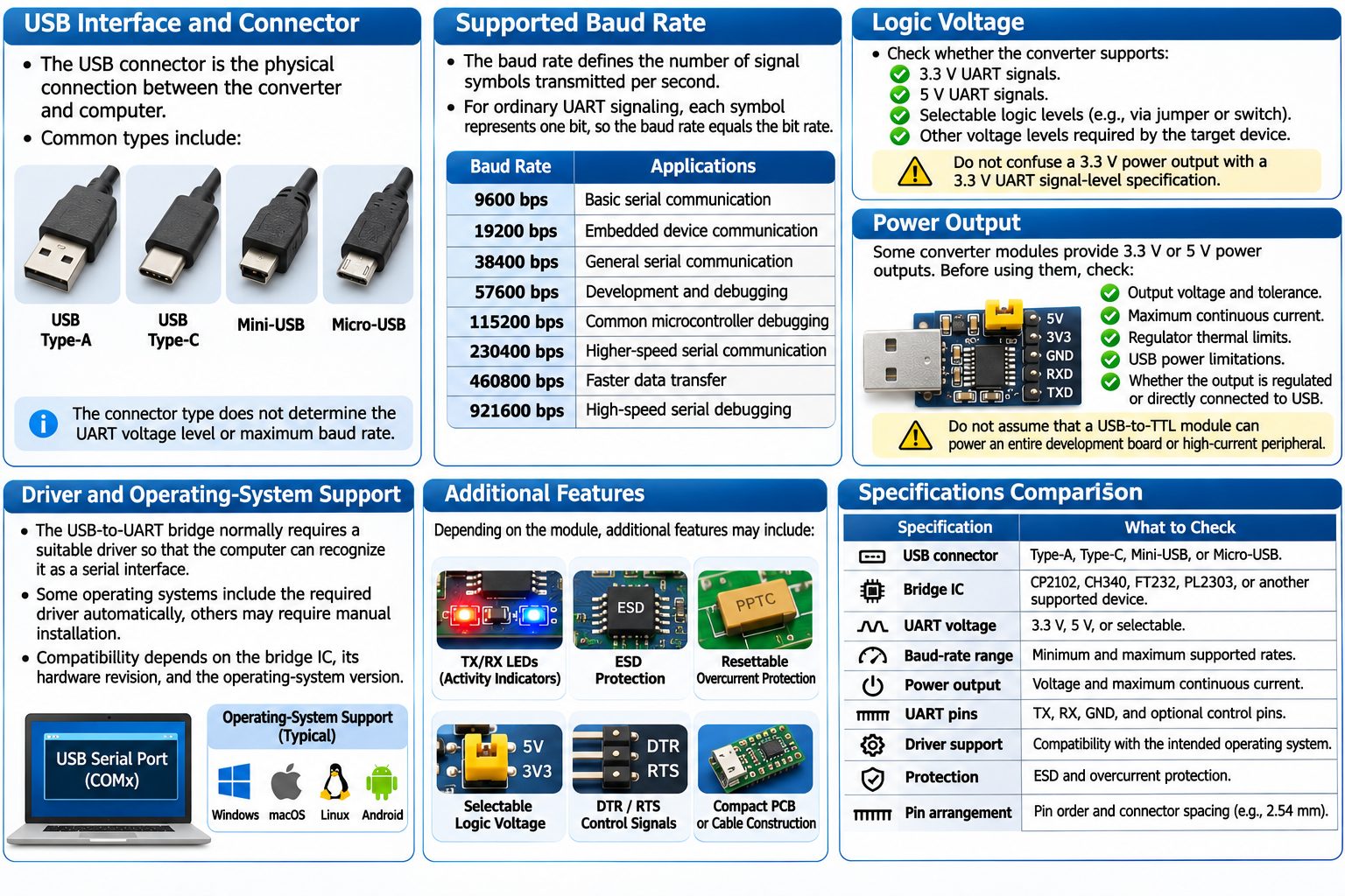


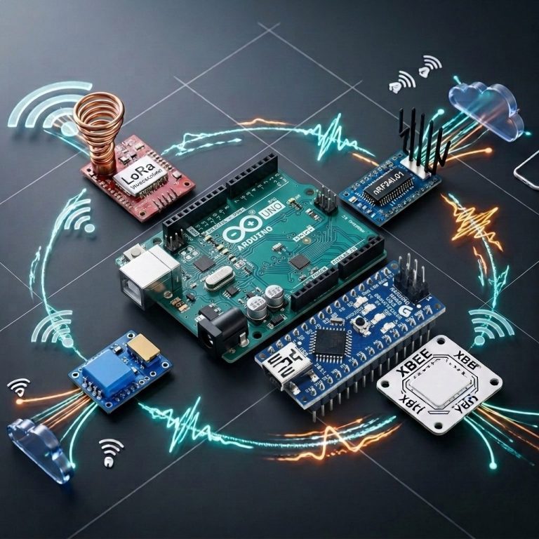

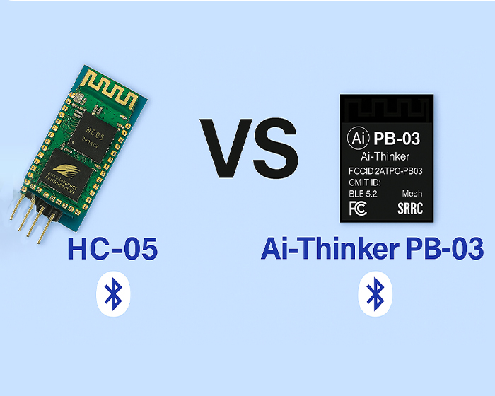
Leave a comment
You must be logged in to post a comment.