WiFi RC Car Using NodeMCU
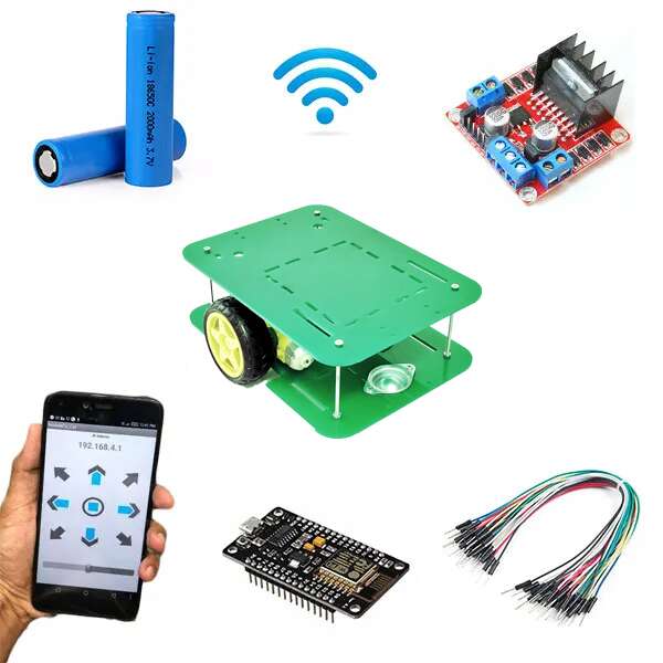
This WiFi remote control car runs with ESP8266 Module also known as NodeMCU. This module is more Powerful than our traditional Arduino UNO Board. It has more memory and also more processing power. The most important thing is that It has Built-in WiFi Module. This small-sized NodeMCU comes with MicroUSB port and also can be operated with 7-12V. You can also program it with Arduino IDE.
This is a simple car made up of simple components. This WiFi controlled robot runs with the wifi signal.
First, when we connect the whole circuit with the Power Supply, then the NodeMCU creates a server with the given SSID and the Password. Now we have to connect with the Hotspot and have to open the same IP. (i.e. 192.168.4.1) we can give the signal to the Browser address bar but it does not look professional.
Components for a Smart car ESP8266 Project:
- ESP8266 WiFi Programming Development Kit
- Robot Platform 2WD
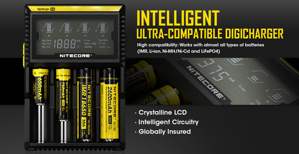
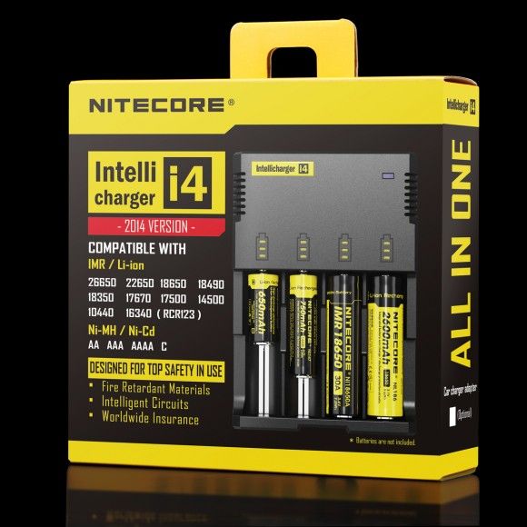
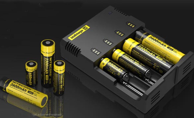
- 18650 Battery Holder
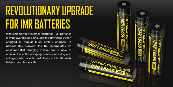
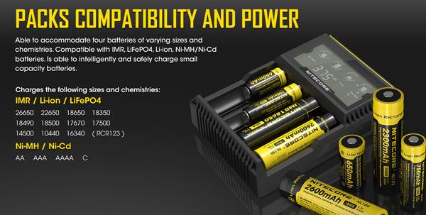
- 18650 Battery X 2
- L298N Motor Driver
- Switch
- Jumper Wires
Tools Needed for ESP8266 Car:
- Soldering Iron
- Soldering Wire
- Flux
- Screwdriver
- Double face tape
ESP8266 Remote Control Car Schematics:
Here is the schematics/ Circuit Diagram of the ESP8266 WiFi Remote Control Car. For the motor driver, I used L298N. This is a high power motor driver capable of running 5V to 35V DC Motor at a maximum of 25W.

Now connect the motor wires with the motor driver. You can connect the motor wires in any direction. At the Troubleshooting section, I am going to discuss more in detail. For now, just connect the wires with the motor driver.
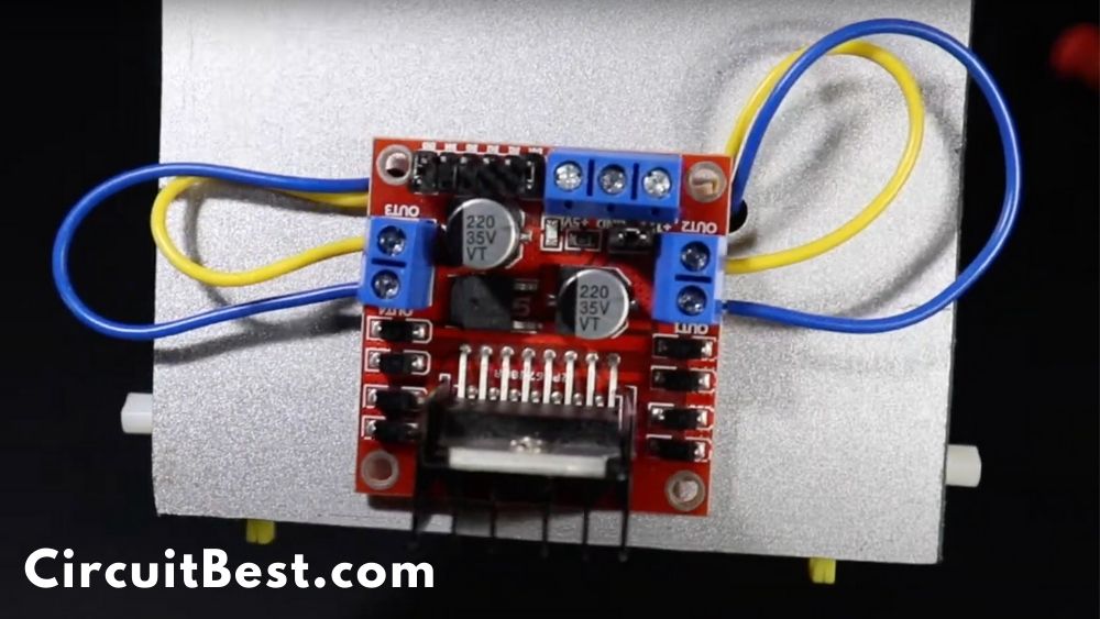
Connect the Battery +Ve wire with the +12v and connect the -Ve wire with the GND wire.
For the wifi module I am using NodeMCU ESP8266 Module. This module has a WiFi module inbuilt in it. So, we don’t need to buy rather more WiFi stuffs.
This WiFi module creates a hotspot. We have to connect the Hotspot through any of our device and have to give the command to the module. Suppose we want to run the car in forwarding so in the coding section, we have declared that if we get “F” data then it will run the car in forward.
In the same way, we have to declare all the things. where we want to move the car. We can add Car Head Light, Backlight, Buzzer as a Horn, and much more. More about that later. It is a topic for another article. For now, Let’s continue our next Step.
Now we have to give the power to the ESP Board. ESP8266 needs 5v. so for the 5v we are using Motor Driver’s 5v output.
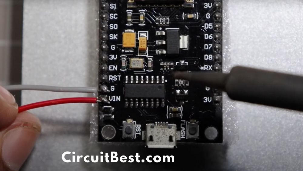
Now we gave to make a communication line between the ESP and the Motor Driver Module. Here are the connected pins diagram for the connection.
| ESP8266 | L298N Motor Driver |
| D3 | Input 4 |
| D4 | Input 3 |
| D5 | Enable A |
| D6 | Enable B |
| D7 | Input 2 |
| D8 | Input 1 |

- First Download the code from the link below. Now open Arduino and Go to File>New.
- Now a new window will appear. Next, Delete all the existing code and Paste the given code.
- In the code, you will find Additional Board Manager URL now copy the URL and do the next step. For Different OS you have a different option.
- MAC: Go to Arduino > Preferences
- Windows: Fille > Preferences
- Now Paste it in the Additional Board Manager URL section and press Ok.
- Now go to Tools > Board > Boards Manager
- Search for ‘ESP8266‘ and install the latest version.
- After the installation Then go to Tools > Board and then select the ESP-12E Module. So, The Board is selected Now.
- Next, Select the Right COM Port.
- Then compile the Programme First and then Upload to NodeMCU. After a few seconds, the code will be compiled and then Uploaded to NodeMCU Car.
Additional Board Manager URL: http://arduino.esp8266.com/stable/package_esp8266com_index.json
- Connect the Car with the battery.
- Now Install the Application link below.
- Connect with the WiFi. In the general case, you will find the Wifi SSID is ‘Make DIY’. You can change the wifi Name by changing the SSID.
- Now open the app and you will be able to control the car with the app.
- The car also has a speed slider by which you can control the speed of the WiFi car Using NodeMCU.
Troubleshoot:
Here I am defining some general troubleshoot of the car.
Not Moving Right Direction:
- Suppose you are pressing the forward button but the car is going to the back or it is rotating to the clockwise or anticlockwise direction. Then you have to do a simple step.
- Just face your car to the forward direction and then press the forward button.
- Next check which wheel is rotating which side.
- If it is rotating in the wrong direction then change motor wires. And your problem will be solved.
NodeMCU WiFi controlled Car Code:
|
1
2
3
4
5
6
7
8
9
10
11
12
13
14
15
16
17
18
19
20
21
22
23
24
25
26
27
28
29
30
31
32
33
34
35
36
37
38
39
40
41
42
43
44
45
46
47
48
49
50
51
52
53
54
55
56
57
58
59
60
61
62
63
64
65
66
67
68
69
70
71
72
73
74
75
76
77
78
79
80
81
82
83
84
85
86
87
88
89
90
91
92
93
94
95
96
97
98
99
100
101
102
103
104
105
106
107
108
109
110
111
112
113
114
115
116
117
118
119
120
121
122
123
124
125
126
127
128
129
130
131
132
133
134
135
136
137
138
139
140
141
142
143
144
145
146
147
148
149
150
151
152
153
154
155
156
157
158
159
160
161
162
163
164
165
166
167
168
169
170
171
172
173
174
175
176
177
178
179
180
181
182
183
184
185
186
187
188
189
190
191
|
/*
Code Name: Arduino Wifi Control Car
Code URI: https://circuitbest.com/category/arduino-projects/
Additional Board Manager URL: http://arduino.esp8266.com/stable/package_esp8266com_index.json
Install: ESP8266 by ESP8266 Community
Author: Make DIY
Author URI: https://circuitbest.com/author/admin/
Description: This program is used to control a robot using a app
that communicates with Arduino through a ESP8266 Module.
App URI: https://drive.google.com/file/d/1pvtWsTeXhcJdpHMfGlFmbGDuH7eoLfoP/view?usp=sharing
Version: 2.0
License: Remixing or Changing this Thing is allowed. Commercial use is not allowed.
*/
#define ENA 14 // Enable/speed motors Right GPIO14(D5)
#define ENB 12 // Enable/speed motors Left GPIO12(D6)
#define IN_1 15 // L298N in1 motors Rightx GPIO15(D8)
#define IN_2 13 // L298N in2 motors Right GPIO13(D7)
#define IN_3 2 // L298N in3 motors Left GPIO2(D4)
#define IN_4 0 // L298N in4 motors Left GPIO0(D3)
#include <ESP8266WiFi.h>
#include <WiFiClient.h>
#include <ESP8266WebServer.h>
String command; //String to store app command state.
int speedCar = 800; // 400 – 1023.
int speed_Coeff = 3;
const char* ssid = “Make DIY”;
ESP8266WebServer server(80);
void setup() {
pinMode(ENA, OUTPUT);
pinMode(ENB, OUTPUT);
pinMode(IN_1, OUTPUT);
pinMode(IN_2, OUTPUT);
pinMode(IN_3, OUTPUT);
pinMode(IN_4, OUTPUT);
Serial.begin(115200);
// Connecting WiFi
WiFi.mode(WIFI_AP);
WiFi.softAP(ssid);
IPAddress myIP = WiFi.softAPIP();
Serial.print(“AP IP address: “);
Serial.println(myIP);
// Starting WEB-server
server.on ( “/”, HTTP_handleRoot );
server.onNotFound ( HTTP_handleRoot );
server.begin();
}
void goAhead(){
digitalWrite(IN_1, LOW);
digitalWrite(IN_2, HIGH);
analogWrite(ENA, speedCar);
digitalWrite(IN_3, LOW);
digitalWrite(IN_4, HIGH);
analogWrite(ENB, speedCar);
}
void goBack(){
digitalWrite(IN_1, HIGH);
digitalWrite(IN_2, LOW);
analogWrite(ENA, speedCar);
digitalWrite(IN_3, HIGH);
digitalWrite(IN_4, LOW);
analogWrite(ENB, speedCar);
}
void goRight(){
digitalWrite(IN_1, HIGH);
digitalWrite(IN_2, LOW);
analogWrite(ENA, speedCar);
digitalWrite(IN_3, LOW);
digitalWrite(IN_4, HIGH);
analogWrite(ENB, speedCar);
}
void goLeft(){
digitalWrite(IN_1, LOW);
digitalWrite(IN_2, HIGH);
analogWrite(ENA, speedCar);
digitalWrite(IN_3, HIGH);
digitalWrite(IN_4, LOW);
analogWrite(ENB, speedCar);
}
void goAheadRight(){
digitalWrite(IN_1, LOW);
digitalWrite(IN_2, HIGH);
analogWrite(ENA, speedCar/speed_Coeff);
digitalWrite(IN_3, LOW);
digitalWrite(IN_4, HIGH);
analogWrite(ENB, speedCar);
}
void goAheadLeft(){
digitalWrite(IN_1, LOW);
digitalWrite(IN_2, HIGH);
analogWrite(ENA, speedCar);
digitalWrite(IN_3, LOW);
digitalWrite(IN_4, HIGH);
analogWrite(ENB, speedCar/speed_Coeff);
}
void goBackRight(){
digitalWrite(IN_1, HIGH);
digitalWrite(IN_2, LOW);
analogWrite(ENA, speedCar/speed_Coeff);
digitalWrite(IN_3, HIGH);
digitalWrite(IN_4, LOW);
analogWrite(ENB, speedCar);
}
void goBackLeft(){
digitalWrite(IN_1, HIGH);
digitalWrite(IN_2, LOW);
analogWrite(ENA, speedCar);
digitalWrite(IN_3, HIGH);
digitalWrite(IN_4, LOW);
analogWrite(ENB, speedCar/speed_Coeff);
}
void stopRobot(){
digitalWrite(IN_1, LOW);
digitalWrite(IN_2, LOW);
analogWrite(ENA, speedCar);
digitalWrite(IN_3, LOW);
digitalWrite(IN_4, LOW);
analogWrite(ENB, speedCar);
}
void loop() {
server.handleClient();
command = server.arg(“State”);
if (command == “F”) goAhead();
else if (command == “B”) goBack();
else if (command == “L”) goLeft();
else if (command == “R”) goRight();
else if (command == “I”) goAheadRight();
else if (command == “G”) goAheadLeft();
else if (command == “J”) goBackRight();
else if (command == “H”) goBackLeft();
else if (command == “0”) speedCar = 400;
else if (command == “1”) speedCar = 470;
else if (command == “2”) speedCar = 540;
else if (command == “3”) speedCar = 610;
else if (command == “4”) speedCar = 680;
else if (command == “5”) speedCar = 750;
else if (command == “6”) speedCar = 820;
else if (command == “7”) speedCar = 890;
else if (command == “8”) speedCar = 960;
else if (command == “9”) speedCar = 1023;
else if (command == “S”) stopRobot();
}
void HTTP_handleRoot(void) {
if( server.hasArg(“State”) ){
Serial.println(server.arg(“State”));
}
server.send ( 200, “text/html”, “” );
delay(1);
}
|
App Link: Download


