

Description
The 74×27 (ex 74HC27) is a chip with three 3-input NOR gates.
In this guide, you’ll learn the things you need to know about this chip to use these 3-input NOR gates in your projects.
Features:
- The 74HC27 is a chip with three 3-input NOR gates.
- Significant power reduction compared to LSTTL logic ICs
- Outputs Can Drive Up To 10 LSTTL Loads
Specifications:
| TYPE | DESCRIPTION |
| Category | Integrated Circuits (ICs) Logic Gates and Inverters |
| Series | 74HC |
| Logic Type | NOR Gate |
| Number of Circuits | 3 |
| Number of Inputs | 3 |
| Voltage – Supply | 2V ~ 6V |
| Current – Quiescent (Max) | 1 µA |
| Current – Output High, Low | 5.2mA, 5.2mA |
| Input Logic Level – Low | 0.5V ~ 1.8V |
| Input Logic Level – High | 1.5V ~ 4.2V |
| Max Propagation Delay @ V, Max CL | 14ns @ 6V, 50pF |
| Operating Temperature | -55°C ~ 125°C |
| Mounting Type | Through Hole |
| Package / Case | 14-DIP |
| Base Product Number | 74HC27 |
There are many versions of the 74×27 chip. They all have the same functionality but with different specifications such as supported voltages and maximum current output.
What does the 74HC27 / 74LS27 do?
The 74×27 gives you three 3-input NOR gates.
A NOR gate is a logic gate that outputs 1 (HIGH) if all of its inputs are 0 (LOW). Therefore, if you input a HIGH in any of the inputs, the output will become LOW. Otherwise, the output will be HIGH.

Truth Table for the 3-input NOR gate
| Input A | Input B | Input C | Output Q |
|---|---|---|---|
| 0 | 0 | 0 | 1 |
| 0 | 0 | 1 | 0 |
| 0 | 1 | 0 | 0 |
| 0 | 1 | 1 | 0 |
| 1 | 0 | 0 | 0 |
| 1 | 0 | 1 | 0 |
| 1 | 1 | 0 | 0 |
| 1 | 1 | 1 | 0 |
How To Use This Chip
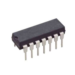
The 74HC27 comes in a 14-pin package, and you need to connect it to power before you can use it. Most 7400 ICs support a VCC voltage of 5V. One difference between the HC and LS version of the chip is that the 74HC27 supports 2V to 6V, while the 74LS27 only supports 5V.
The maximum current you can pull out of one output pin is 4 mA when the pin is high (sourcing) or 16 mA when the pin is low (sinking). This can differ between models, so check the datasheet of your model to verify.
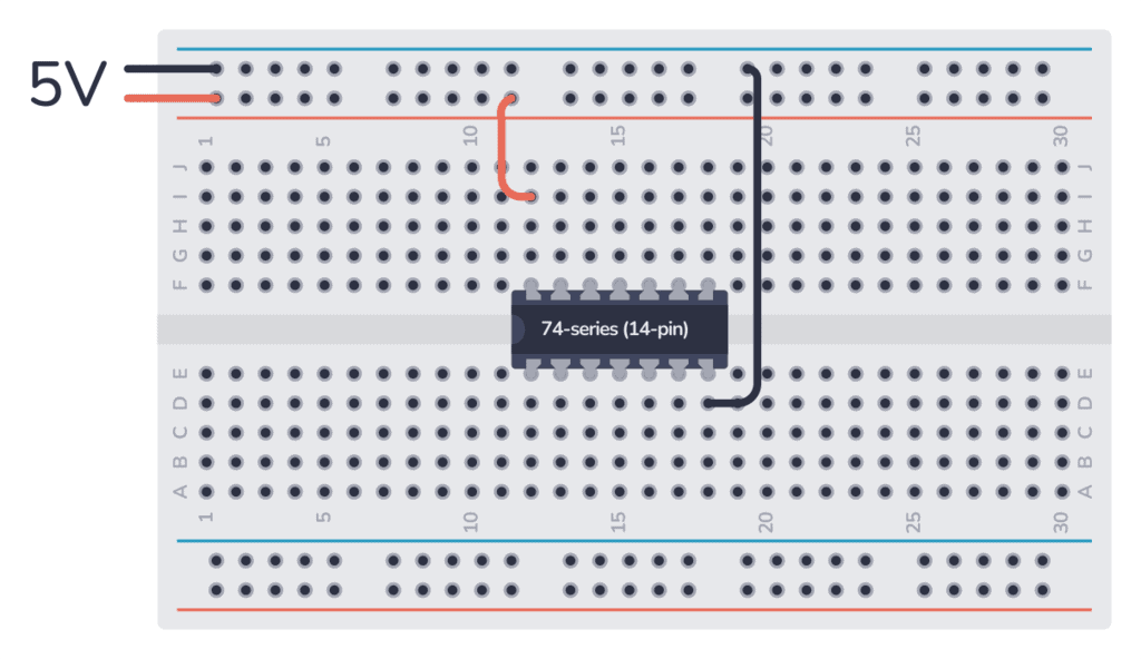
Once you’ve connected it to power, you can use any of the three 3-input NOR gates inside.
The 74HC27/74LS27 IC connected to power
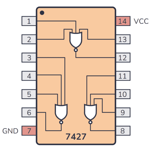
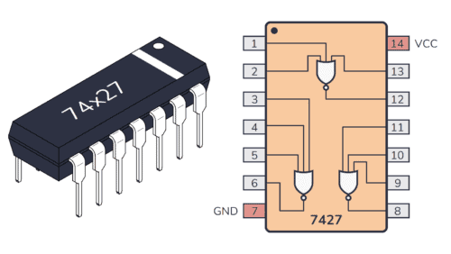
The pinout diagram for the 74×27 IC
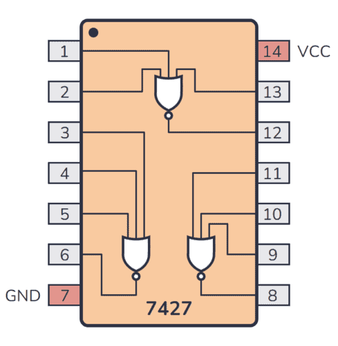
Pin overview for the 74×27 IC
| Pin # | Type | Description |
|---|---|---|
| 1 | Input | Input to the first NOR gate. |
| 2 | Input | Input to the first NOR gate. |
| 3 | Input | Input to the second NOR gate. |
| 4 | Input | Input to the second NOR gate. |
| 5 | Input | Input to the second NOR gate. |
| 6 | Output | Output from the second NOR gate. |
| 7 | Power | Connect to ground (GND). |
| 8 | Output | Output from the third NOR gate. |
| 9 | Input | Input to the third NOR gate. |
| 10 | Input | Input to the third NOR gate. |
| 11 | Input | Input to the third NOR gate. |
| 12 | Output | Output from the first NOR gate. |
| 13 | Input | Input to the first NOR gate. |
| 14 | Power | Positive power supply (VCC). Connect to +5V power. |
Applications:
• Alarm / tamper detect circuit
• S-R latch


Reviews
There are no reviews yet.