

The CD4510 is an up/down BCD counter that you can preset. Since the output is in BCD format, it means it counts from 0 up to 9 only. Unlike its brother, the CD4516, which counts from 0 to 15. The counter value is given in binary, so for example, a ‘5’ would be output as 0101:
Q4=LOW
Q3=HIGH
Q2=LOW
Q1=HIGH
Every time the clock pin goes from low to high, the output increases or decreases by 1, depending on the state of the UP/DOWN pin. The counter can be preset to any value that is present on pins P1 to P4 by setting the PRE pin to HIGH.
Pin Overview
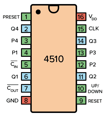 Pinout for the CD4510 IC
| Pin Name | Pin # | Type | Description |
|---|---|---|---|
| VDD | 16 | Power | Supply Voltage (+3 to +15V) |
| GND | 8 | Power | Ground (0V) |
| Preset | 1 | Input | Sets the counter to whatever is on P1-P4 |
| Carry-In | 5 | Input | Carry in from any previous stage, otherwise set LOW |
| Carry Out | 7 | Output | Goes low when the lowest or highest value is reached |
| Reset | 9 | Input | Sets output to 0000 |
| Up/Down | 10 | Input | Set HIGH to count up (or LOW to count down) |
| Clock | 15 | Input | Increases/decreases counter when going LOW to HIGH |
| Q1 to Q4 | 6,11,14,2 | Output | The counter value |
| P1 to P4 | 4,12,13,3 | Input | Value for presetting the counter |
What is an Up/Down BCD Counter?
An up/down counter is – you guessed it – a counter that can count either up or down. With every rising clock edge, the counter either increases by one (if UP/DOWN pin is HIGH) or it decreases by one (if UP/DOWN pin is LOW).
BCD stands for Binary-Coded Decimal. This means it only counts from 0 to 9, although it has 4 bits that would allow it to count to 15. If you need a counter that counts all the way to 15, check out the 4516 instead.
This counter can only count from 0 up to 15 – or the other way around. But by combining several counters and using the carry-in/carry-out pins, you can count as high as you want.
By connecting the output value to a display and the clock input to a 1 Hz clock source, it can be used to create a stopwatch or countdown timer.
How To Use The CD4510
First of all, you need to connect the VDD pin (pin 16) to your positive supply terminal and the GND pin (pin 8) to your negative supply terminal.
You can use a power supply voltage between 3V and 15V. Although, some versions of the 4510 chip support up to 20V. Check your datasheet for exact values.
The Q1 to Q4 pins are the outputs that give you the current counter value. Q4 is the most significant bit (MSB).
The P1 to P4 pins are the inputs if you want to preset the counter to a certain value. Whenever the Preset pin is high, the counter is set to the value on these pins. The Reset pin resets the counter to 0.
When the CLK pin goes from LOW to HIGH (rising edge), the counter will either increase or decrease by 1. If the UP/DOWN pin is HIGH, the counter increases. If it’s LOW, the counter decreases.
Normally, set the Carry In pin to LOW. Unless you are combining several chips – then you want to connect it to the Carry Out pin from the previous chip.
4510 Datasheet
Download the PDF datasheet for the IC 4510 here:
Reviews
There are no reviews yet.