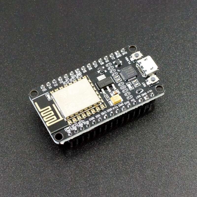
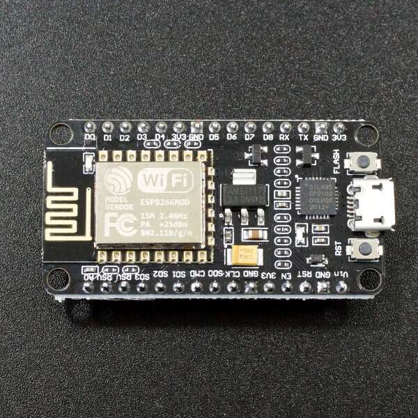
ESP8266 NodeMCU WiFi Programming Development Kit 30-Pin With CP2102 Micro USB
The ESP8266 NodeMCU development kit (the NodeMCU family of breakout/dev boards described in the PDF) is a breadboard-friendly, USB-programmable platform that places the ESP8266 Wi-Fi SoC onto a simple development board so you can write and load networked applications quickly. The board integrates the ESP8266 module, exposes its GPIOs and power rails on convenient 0.1″ headers, and pairs the module with a USB–UART interface (the author recommends CP2102 USB→UART adapters in the book) so a developer can program, monitor and debug over a single USB connection.
Functionally, the NodeMCU kit turns the ESP8266 into an easy-to-use microcontroller + Wi-Fi platform: it provides a serial boot/programming path, exposes the UART for console/debug output, and presents the chip’s Wi-Fi and TCP/IP capabilities through simple libraries and examples (the book covers AT commands, native SDK usage and Arduino/IDE integration). This removes much of the low-level setup, letting you focus on writing networked code (HTTP, TCP/UDP, MQTT and similar).
Physically and educationally the kit is aimed at makers and learners: it’s engineered so you can plug it into breadboards, connect sensors/actuators to exposed pins, and iterate fast. The PDF emphasizes practical workflows flashing binaries, using serial consoles for diagnostics, and common helper circuits (power decoupling, reset/boot jumper arrangements) making the NodeMCU kit an approachable bridge from experiments to deployed, Wi-connected prototypes.
Features:
- Built around the ESP8266 Wi-Fi SoC (native TCP/IP + Wi-Fi).
- USB-programmable / USB-UART debug and flashing (CP2102 USB↔UART commonly used).
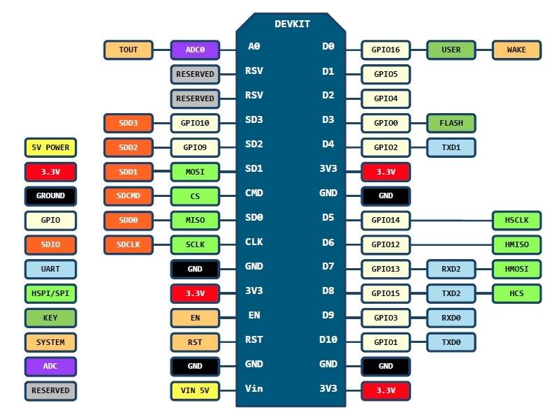
- Breadboard-friendly headers that break out GPIOs, power rails and control signals.
- Supports AT command usage and native SDK (C) and Arduino IDE development flows described in the book.
- Easy boot/flashing support via GPIO0/RESET wiring and documented boot modes.
Specifications:
| Parameter | Value |
|---|---|
| Core / SoC | ESP8266 (Ten silica L106 32-bit) . |
| Typical CPU clock | 80–160 MHz. |
| Supply / I/O voltage | 3.3 V (board designs provide USB-to-3.3V regulation). |
| Current consumption | ~10 µA (deep sleep) → up to ~170 mA (TX/active) (profile in PDF). |
| Flash | External flash supported (up to ~16 MB attachable as noted). |
| GPIOs | 17 (multiplexed with other functions; exposed pins vary by board). |
| ADC | 1 analog input (10-bit / 1024 steps as documented). |
| Wi-Fi standard | 802.11 b/g/n. |
| Max concurrent TCP connections | Up to 5 (SDK limit described). |
| Default serial baud (typical) | 115200 (boot/console speed noted in examples). |
Applications:
- IoT Smart Home Automation Systems.
- Wireless Sensor Networks and Data Logging.
- IoT Weather Stations.
- Web Server and HTTP Client Applications.
- MQTT Clients for IoT Messaging.
- WiFi-Controlled Robots and Drones.
- Over-the-Air (OTA) Firmware Updates.
- IoT Smart Gardening and Irrigation Systems.
- WiFi Remote Controls for Appliances.
- Network Clocks and NTP Time Displays.
- Data Bridge for Serial-to-WiFi Communication.
- IoT Notifications and Alert Systems.
- WiFi-Controlled LED and Lighting Systems.
- IoT Access Control and Security Systems.
- Prototyping and Proof-of-Concept Development.
Package Contents:
- 1x ESP8266 NodeMCU WiFi Programming Development Kit 30-Pin With CP2102 Micro USB