DESCRIPTION
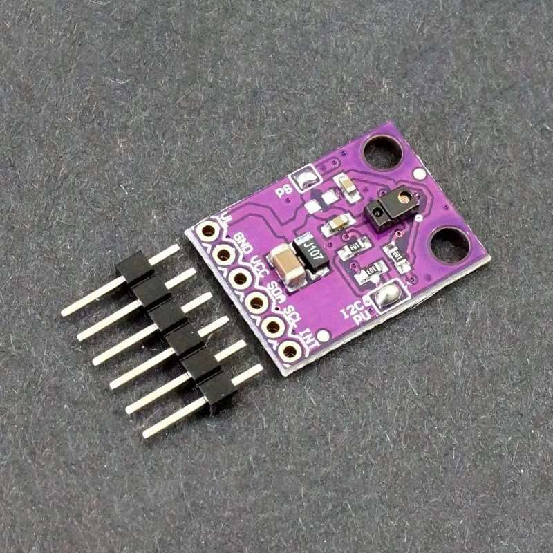
The GY-9960-3.3 APDS-9960 Gesture Sensor Module provides a gesture sensor, proximity sensor, ambient light sensor and RGB color sensor all in a small package with I2C interface.
PACKAGE INCLUDES:
- GY-9960-3.3 APDS-9960 Gesture Sensor Module
- Male header strip
KEY FEATURES OF GY-9960-3.3 APDS-9960 GESTURE SENSOR MODULE:
- Gesture recognition using reflected IR
- Digital proximity sensing using reflected IR
- Separate Red/Green/Blue light intensity sensors
- Ambient (clear) light intensity sensor
- IR light blocking filter
- Interrupt output available
- I2C interface with good library support
- 3.3V operation
The APDS-9960 sensor was used in Samsung Galaxy phones to provide a number of functions. Primary use is for gesture recognition of swiping UP, DOWN, LEFT or RIGHT. It can also provide proximity sensing which was used to detect when the phone was placed near the ear. It also has ambient light and RGB color detection. These last two were used to adjust the brightness and color balance of the backlight depending on lighting conditions.
Though these are fairly complicated little devices, excellent library support makes them easy to use.
Operational Theory
Gesture Detection
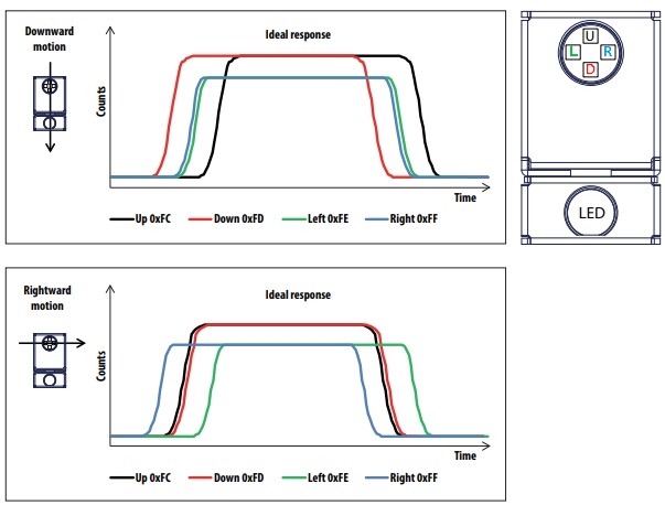
The gesture detection uses four directional photodiodes to sense the reflected IR from the built-in IR LED. The sensor that first ‘sees’ an object approaching and first to see it leave provides the direction from which the object came. The sensor works best when the finger or object passes within 1-2″ of it.
A built-in gesture engine converts the data into basic up/down/left/right movements which are reported by the available libraries, but the device is capable of more complex gestures.
The graphic below from the datasheet shows how the basic gesture detection works.
Proximity Sensor
The proximity sensor uses reflected IR to determine the relative distance to an object. Both the IR transmitter LED and photodiode detectors are located in the small black package. It has a maximum detection range of about 6″ depending on the surface and a minimum range of about 1″
With no object detected, the sensor will report 255 or something close to that reading.. When an object is detected the reading will approach 0 as the object moves closer and will read 0 at about 1″ distance from the sensor.
Color and Ambient Light Sensor
The color and ambient light sensing functionality uses an array of red / green / blue / clear filtered photodiodes with IR filters over them to minimize the impact of IR light. The measurement data is provided as 16-bit results.
I2C Interface
The module communicates via a standard I2C interface. The I2C address is fixed at the address of 0x39.
The module operates at 3.3V, so if connecting to a 5V MCU the I2C lines need to go through a bi-directional logic level translator like the Logic Level Converter 4-Ch Bi-Directional Module
Powering the Module
The module must be powered by 3.3V (2.4 – 3.6V range). Hooking it up to 5V will destroy it.
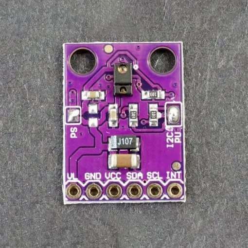
Setting the Jumpers
The front of the module has 2 solder jumpers labeled PS and I2C PU. In most applications you can ignore these and leave them as shipped.
PS – This solder jumper connects the power supplies of the sensor and IR LED together. As shipped, the jumper is closed and you only need to supply power to the VCC pin. If the jumper is open, you will need to provide power to both the VCC (2.4 – 3.6V) and VL (3.0 – 4.5V). This jumper is closed by default. To open it, use solder wick to remove the solder blob.
I2C PU – This is a 3-way solder jumper used to connect the I2C 10K pull-up resistors to the SDA and SCL circuits. As shipped, this jumper is closed and the pull-up resistors are in-circuit. To open it, use solder wick to remove the solder blob. You may want to do this if you have other pull-up resistors already in circuit.
Module Connections
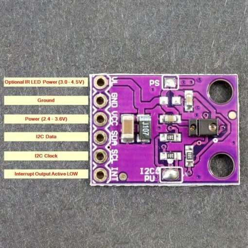
The module brings out the following connections.
1 x 6 Header
- VL= Optional power to IR LED if PS jumper is removed. Must be 3.0 – 4.5V
- GND = Ground connects to ground on the MCU
- VCC = Power input. Connects to 3.3V on the MCU (2.4 – 3.6V)
- SDA = I2C Data line. Connects to SDA on MCU
- SCL = I2C Clock line. Connects to SCL on MCU
- INT = Interrupt output active LOW. Output is open-collector so requires pull-up resistor. Connects to an interrupt input on the MCU if used.
Module Assembly
The module ships with the male header strip loose. This allows the header to be soldered to the top or bottom of the module depending on the planned use or wires can be used to make the connections.
For breadboard use, we put the headers on the bottom. Soldering is easiest if the header is inserted into a breadboard to hold it in position during the soldering process.
OUR EVALUATION RESULTS:
The APDS-9960 is one of the best low cost gesture sensors available and there is excellent library support from Arduino since they have a board with this sensor designed into it and there are very similar libraries available from Adafruit and Sparkfun as well. In the example below we used the Arduino library that can be loaded from the IDE. All of the libraries come with example programs that illustrate the main features of the device.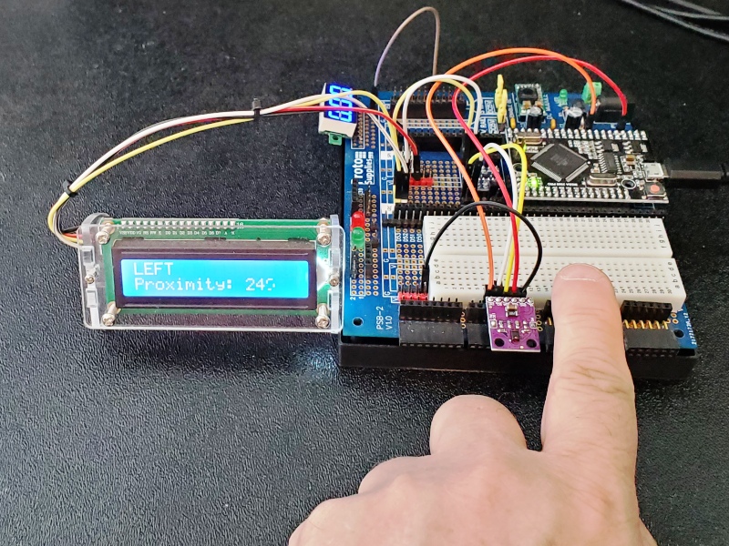
Our example program here illustrates the gesture and proximity sensor functionality. The data is reported out to the Serial Monitor window and you can optionally connect a 16×2 I2C LCD display to have the results displayed as well.
To use this software first load the Arduino_APDS9960.h library. This can be done from within the Arduino IDE under Tools / Manage Libraries
Connect that module I2C SDA and SCL lines to the same on the MCU. If using a 5V MCU, you should use a bi-directional logic level translator to prevent possible damage. Connect 3.3V to VCC and ground to GND. You can ignore the INT and VL pins for now.
If using a 16×2 I2C LCD display, connect it the same way but power it off the 5V. You may need to change the I2C address in the program below.
Once the program is running, open the Serial Monitor window and ensure it is set for 9600 baud.
APDS9960 Gesture and Proximity Test Program
/*
  APDS9960 - Gesture Sensor Test

  This example reads gesture data from the APDS9960 sensor and prints any
  detected gestures and proximity infor to the Serial Monitor and to a 16x2
  I2C LCD display if attached.

  Gesture directions are as follows:
  - UP:    from header side
  - DOWN:  toward header side
  - LEFT:  from INT pin side
  - RIGHT: toward INT pin side
*/
#include <Arduino_APDS9960.h>
#include <Wire.h>
#include <LiquidCrystal_I2C.h>

LiquidCrystal_I2C lcd(0x27, 16, 2); // set LCD address to 0x27 for 16x2 display
int proximity = 0;

//===============================================================================
//  Initialization
//===============================================================================
void setup() {
  Serial.begin(9600);

  lcd.begin();
  lcd.clear();
  lcd.backlight();      // Make sure backlight is on

  if (!APDS.begin()) {
    Serial.println("Error initializing APDS9960 sensor!");
  }

  // for setGestureSensitivity(..) a value between 1 and 100 is required.
  // Higher values makes the gesture recognition more sensitivee but less accurate
  // (a wrong gesture may be detected). Lower values makes the gesture recognition
  // more accurate but less sensitive (some gestures may be missed).
  // Default is 80 which we are using.
  APDS.setGestureSensitivity(80);

  Serial.println("Detecting gestures ...");
  lcd.setCursor(0, 1);
  lcd.print("Proximity: ");
}
//===============================================================================
//  Main
//===============================================================================
void loop() {
  // Report proximity reading (0-255) if < 240 to avoid clutter
  if (APDS.proximityAvailable()) {
    proximity = APDS.readProximity();
    if (proximity < 240) {  // Suppress reporting readings when nothing close
      Serial.print("Proximity Detected: ");
      Serial.println (proximity);
      lcd.setCursor(11, 1);  //Move cursor to character 11 on line 1
      lcd.print(proximity);
      lcd.print("   ");     // Erase any extra characters left from last reading
    }
  }

  if (APDS.gestureAvailable()) {
    // a gesture was detected, read and print to serial monitor
    // and LCD if connected
    int gesture = APDS.readGesture();
    lcd.setCursor(0, 0);  //Move cursor to character 0 on line 0
    switch (gesture) {
      case GESTURE_UP:
        Serial.println("Detected UP gesture");
        lcd.print("UP   ");
        break;

      case GESTURE_DOWN:
        Serial.println("Detected DOWN gesture");
        lcd.print("DOWN ");
        break;

      case GESTURE_LEFT:
        Serial.println("Detected LEFT gesture");
        lcd.print("LEFT ");
        break;

      case GESTURE_RIGHT:
        Serial.println("Detected RIGHT gesture");
        lcd.print("RIGHT");
        break;

      default:
        // ignore
        break;
    }
  }
}
TECHNICAL SPECIFICATIONS
| Operating Ratings | ||
| Vcc | 2.4 – 3.6V (3.3V typ) | |
| Interface | I2C (up to 400kHz) | |
| Dimensions | L x W (PCB) | 21 x 15.5mm (0.83 x 0.61″) |
| Datasheet | Avago | APDS-9960 |