Microphone Sound Detection Sensor Module 4 PIN
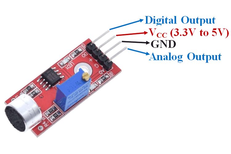
The sound detector with a small electret microphone, a voltage supply range from 3.3 V to 5 V. The module is easy to use, has two outputs: an analog – to measure the intensity of the digital signal and changing state when exceeding a certain level. This Sound Detection Sensor Module consists of a Microphone, resistors, capacitor, potentiometer, comparator LM393 IC, Power, and status LED in an integrated circuit.
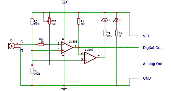
LM393 Comparator IC is used as a voltage comparator in this Sound Detection Sensor Module. Pin 2 of LM393 is connected to Preset (10KΩ Pot) while pin 3 is connected to Microphone. The comparator IC will compare the threshold voltage set using the preset (pin2) and the Microphone pin (pin3). The microphone in the Sound sensor module detects the sound. This sound is fed into the LM393 IC. Using the onboard preset, you can adjust the threshold (sensitivity) of the digital output.
Features:
- Built-in LM393 voltage comparator
- Electret microphone for sound detection
- Adjustable sensitivity via onboard potentiometer
- Digital output (HIGH/LOW) based on sound threshold
- Compact and easy to integrate with Arduino, Raspberry Pi, and other microcontrollers
- Onboard power and output indicator LEDs
- Operates on 3.3V to 5V DC supply
PINOUT:

| Pin | Description |
|---|---|
| VCC | The Vcc pin powers the module, typically with +5V |
| GND | Power Supply Ground |
| DO | Digital Output Pin. Directly connected to digital pin of Microcontroller |
| AO | Analog Output Pin. Directly connected to an analog pin of Microcontroller |
Specifications:

| Specification | Details |
|---|---|
| Supply Voltage | 3.3 V to 5 V |
| Comparator | LM393 with threshold preset |
| Output | Analog signal and digital |
| Connector | 4-pin |
| Microphone | Electret |
| Mounting Hole | 3 mm |
| Frequency Range | 50 Hz to 20 kHz |
| Sensitivity | 48 dB to 66 dB |
| Operating Temperature | -40 °C to 85 °C |
| Module Dimensions | 35 x 15 mm |
Using sound sensor
The sensor has a 4-pin connector with analog and digital output A0 D0 to be attached to the pin of the microcontroller, e.g.an Arduino.

How to Use Sound Detection Sensor Module
Sound Detection Sensor Module consists of four pins i.e. VCC, GND, DO, AO. Digital out pin is connected to the output pin of LM393 comparator IC while the Analog pin is connected to Microphone. The internal Circuit diagram of the Sound Detection Sensor Module is given below.

Using Sound Detection Sensor Module with a microcontroller is very easy. Connect the Analog/Digital Output pin of the module to the Analog/Digital pin of Microcontroller. Connect VCC and GND pins to 5V and GND pins of Microcontroller. When the sound level exceeds the setpoint, an LED on the module is illuminated and the output is set low.
Applications:
- Clap-activated switches
- Sound-activated lighting systems
- Voice-controlled devices
- Security alarms triggered by sound
- DIY electronics and robotics projects


Reviews
There are no reviews yet.