-

TDA9105 Deflection Processor for Multi-Sync Monitors 12V 40mA IC DIP-42 (Wide)
55.00 EGP55.00 EGP×

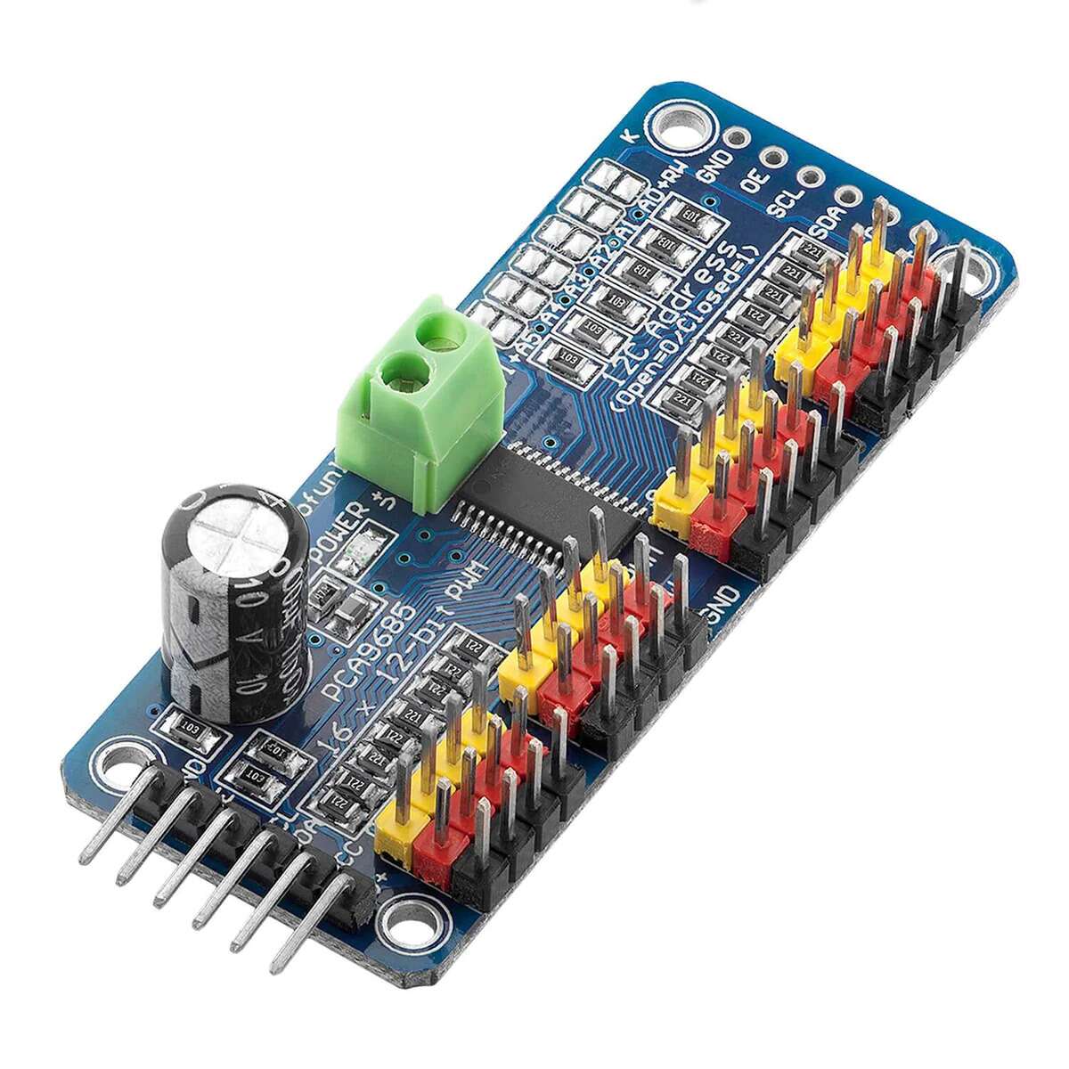
PCA9685 Servo Motor 16 Channel Driver
PCA9685 Control 16 servos/LEDs with precision using this I²C PWM driver. 12-bit resolution, adjustable frequency, expandable. Ideal for robotics and automation.
190.00 EGP
Buy NowPCA9685 Servo Motor 16 Channel Driver
The PCA9685 is a 16-channel, 12-bit PWM servo motor driver controlled via the I²C-bus. Originally designed as an LED controller, its precise pulse width modulation (PWM) capabilities make it an excellent choice for driving servo motors in applications such as robotics, automation, animatronics, and more. With individual control over each of its 16 channels and a resolution of 4096 steps, this driver enables accurate positioning of multiple servo motors simultaneously. Operating on a supply voltage range of 2.3 V to 5.5 V and featuring a user-friendly I²C interface, the PCA9685 integrates seamlessly with popular microcontrollers like Arduino and Raspberry Pi, making it a versatile addition to any electronics project.
PLEASE NOTE: The PWM output pins on this module are capable of sinking a maximum of 25mA or sourcing a maximum of 10mA. Do not attempt to drive high-current devices such as motors, bulbs, etc, directly from these pins as you will risk damaging the module. For servos, power is provided externally via the terminal header and only a small amount of current is drawn by the servo from each PWM pin.
Features:
- 16 Independent PWM Channels: Control up to 16 servo motors with individual precision.
- 12-Bit Resolution: Offers 4096 steps per channel for high-precision servo positioning.
- Programmable PWM Frequency: Adjustable from 24 Hz to 1526 Hz, typically set to 50 Hz for standard servo motors.
- Individual Timing Control: Programmable on and off times for each channel to reduce power surges and mechanical stress.
- I²C-Bus Interface: Supports Fast-mode Plus (Fm+) with speeds up to 1 MHz for efficient communication.
- Scalable Design: 6 hardware address pins allow connection of up to 62 devices on the same I²C-bus.
- Group Control: Software-programmable I²C addresses enable simultaneous control of multiple devices or groups.
- Output Enable Pin: Active LOW Output Enable (OE) pin to easily enable or disable all outputs.
- Internal Oscillator: 25 MHz typical internal oscillator; optional external clock input up to 50 MHz.
- Power Efficiency: Low standby current and support for hot insertion.
- Wide Operating Range: Functions reliably from -40°C to +85°C.
Specifications:
| Specification | Details |
|---|---|
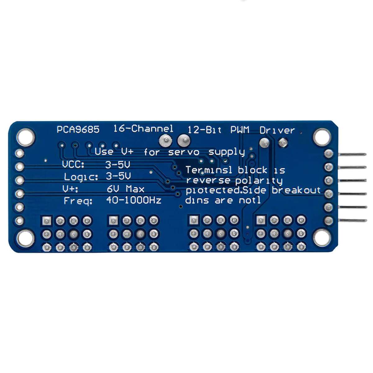
| Supply Voltage: | 3 V to 6 V |
| I²C-Bus Frequency: | Up to 1 MHz (Fast-mode Plus) |
| PWM Resolution: | 12 bits (4096 steps) |
| PWM Frequency Range: | 24 Hz to 1526 Hz |
| Output Drive Capability: | 25 mA sink, 10 mA source at 5 V |
| Package Options: | TSSOP28, HVQFN28 |
| Operating Temperature: | -40°C to +85°C |
| Output Configuration: | Totem pole or open-drain (software selectable, default totem pole) |
| Internal Oscillator: | 25 MHz |
| External Clock Input: | Up to 50 MHz (max) |
| Number of Channels: | 16 |
| ESD Protection: | Exceeds 2000 V HBM, 200 V MM, 1000 V CDM |
| Latch-up Testing: | Exceeds 100 mA per JESD78 |
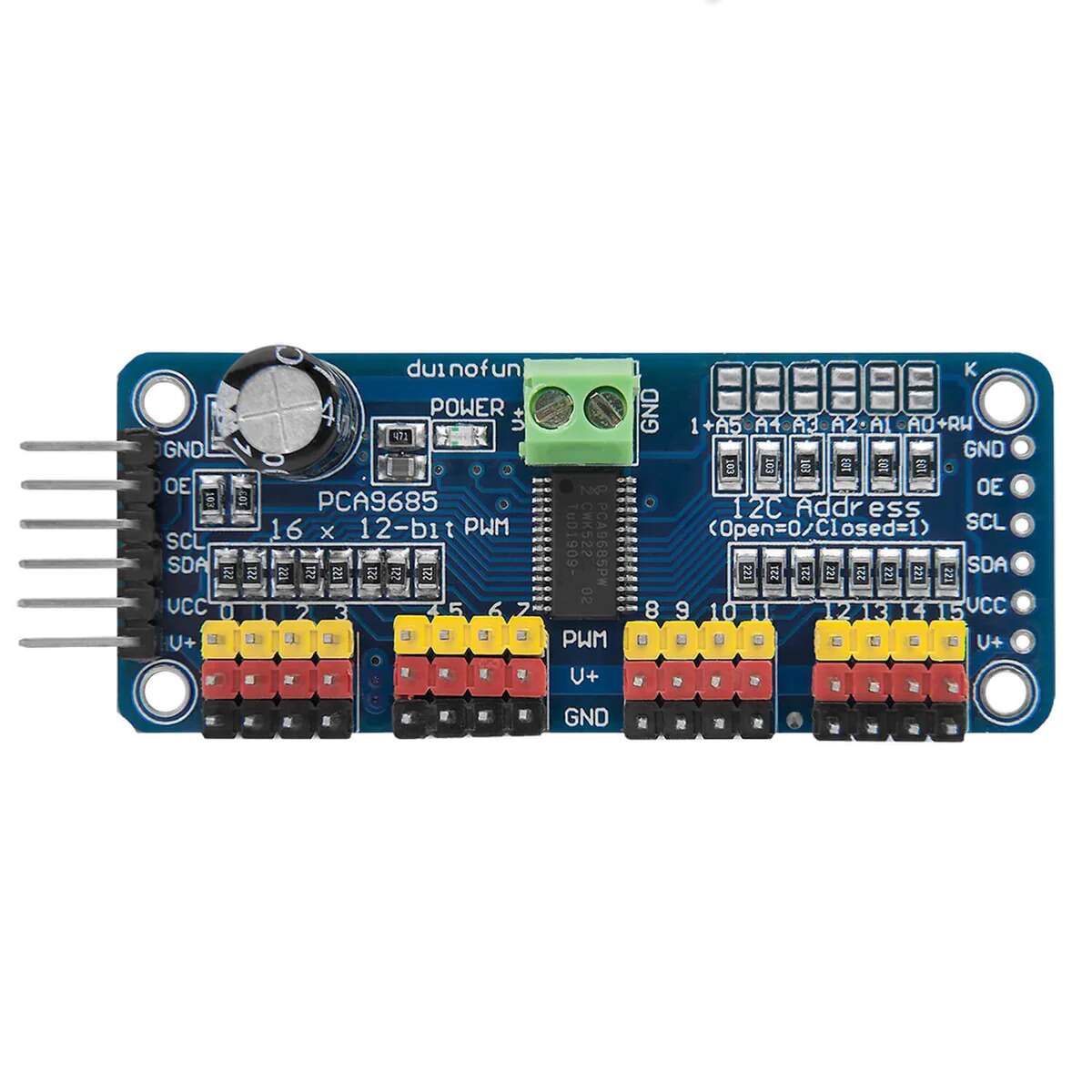
Pinout:

Pinout:
| Pin | Description |
|---|---|
| GND | This is the power and signal ground pin, which must be connected. |
| VCC | This is the logic power pin. Connect this to the logic level you want to use for the PCA9685 output (should be 3–5V max!). It’s also used for the 10k pull‑ups on SCL/SDA, so unless you have your own pull‑ups, have it match the microcontroller’s logic level too. |
| V+ | This is an optional power pin that will supply distributed power to the servos. If you are not using servos you can leave it disconnected. It is not used at all by the chip. You can also inject power from the 2‑pin terminal block at the top of the board. You should provide 5–6 VDC if you are using servos. If necessary, you can go higher to 12 VDC, but if you mess up and connect VCC to V+, you could damage your board. |
| SCL | I2C clock pin. Connect to your microcontroller I2C clock line. Can use 3V or 5V logic, and has a weak pull‑up to VCC. |
| SDA | I2C data pin. Connect to your microcontroller I2C data line. Can use 3V or 5V logic, and has a weak pull‑up to VCC. |
| OE | Output enable. Can be used to quickly disable all outputs. When this pin is low, all pins are enabled. When the pin is high, the outputs are disabled. Pulled low by default, so it’s an optional pin. |
Applications:
- Robotics and Automation: Ideal for controlling multiple joints or actuators in robotic systems.
- Animatronics and Puppetry: Enables lifelike movements in animated figures.
- Remote-Controlled Vehicles and Drones: Perfect for managing steering, throttle, and other servo-driven components.
- Camera Gimbals and Stabilization Systems: Provides precise multi-axis control for camera stabilization.
- Multi-Servo Projects: Suited for any application requiring accurate control of multiple servo motors.
Package Contents:
- 1x PCA9685 Servo Motor 16 Channel Driver.