


Description:
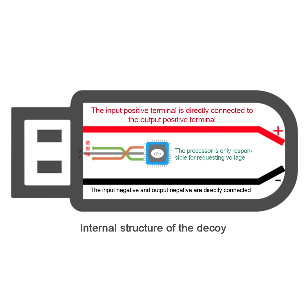
It is a PD2.0/3.0 decoy.It is often used to use power banks with PD protocol such as power banks or chargers to trick the corresponding voltage to power notebooks and routers.
Features:
- It supports PD3.0 and PD2.0 voltage deception output, and the mode can be switched freely.
- It has a key lock function to prevent misoperation.
- It has an LED output indicator to show the working status.
- The parameters are automatically saved, and the last decoy setting is executed when the power is turned on again.
- Ultra-low power consumption, support 100W output.
Parameter:
- Product Name: PD2.0/3.0 Decoy
- Input Voltage: DC 5V
- Output Voltage: 5V>9V>12V>15V>20V
- Maximum Output Voltage: 20V
- Maximum Output Current: 5A
- Work Temperature: -25℃~85℃
- Work Humidity: 5%~95%RH
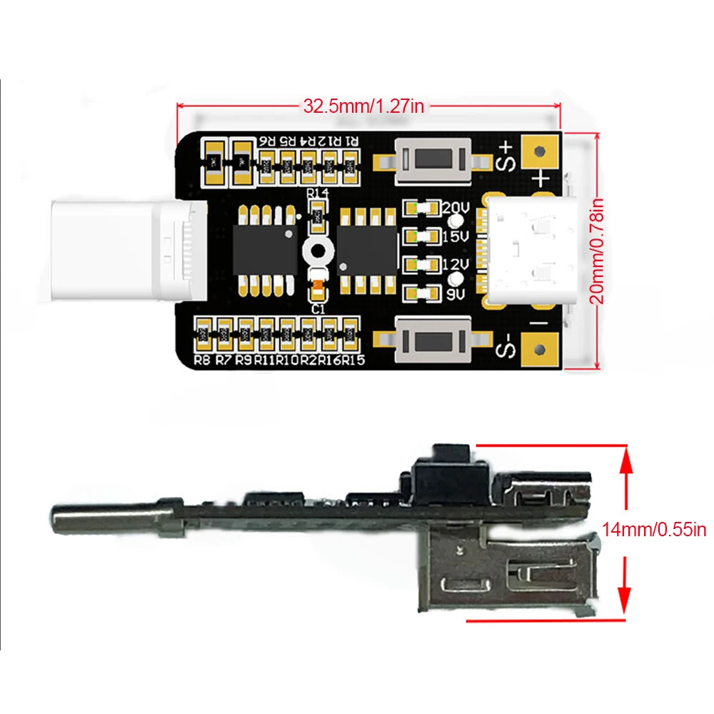
- Size: 44x20x15mm
Instructions for Use (must use a power supply with PD protocol):
- Press and hold the S- button, insert the module into the power supply, and then reset to 5V output (“>>” means power on).
- Press and hold the S+ button, and then insert the module into the power supply. At this time, switch whether to turn on the key lock and save the state after power-on. If the key lock is unlocked, it must be unlocked to adjust the voltage after power-on to prevent misoperation.
- After power on, press and hold S+ button without letting go, then press S- button, and unlock when there is a button lock.
- After powering on, press and hold S- button without letting go, then press S+ button to lock the button.
- Quick start: Plug the board into the PD power supply. At this time, the LED light indicates the current setting decoy voltage. If it is not on, it is the default 5V.
- Adjust the output voltage: The board is locked by default, and you need to unlock it first. The method is to press and hold S+ button and then press S- button. At this time,the unlocking is complete and you can release the button. Then click S+ button to increase the voltage or click S- button to decrease the voltage.
Instructions for Use of Test Function:
- Press S- button and S+ button at the same time and then power on, the module enters the test mode, and the output voltage will automatically cycle from 5V>9V>12V>15V>20V. The voltage change time can be adjusted by S+ button and S-button, in seconds.
- This function is a test function, the mode is not saved, and the switching time can be saved.
Interface Description:
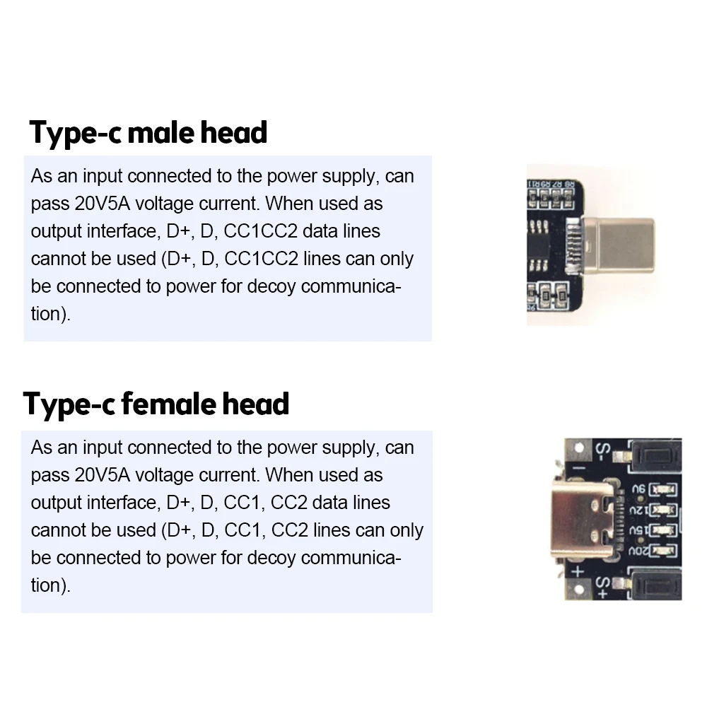
- Type-C Male: used as input to connect PD power supply and can pass 20V 5A voltage and current.
- Type-C Female: used as input to connect PD power supply, and also as output interface (At this time, keep the CC line hanging), the voltage and current of 20V5A can be passed.
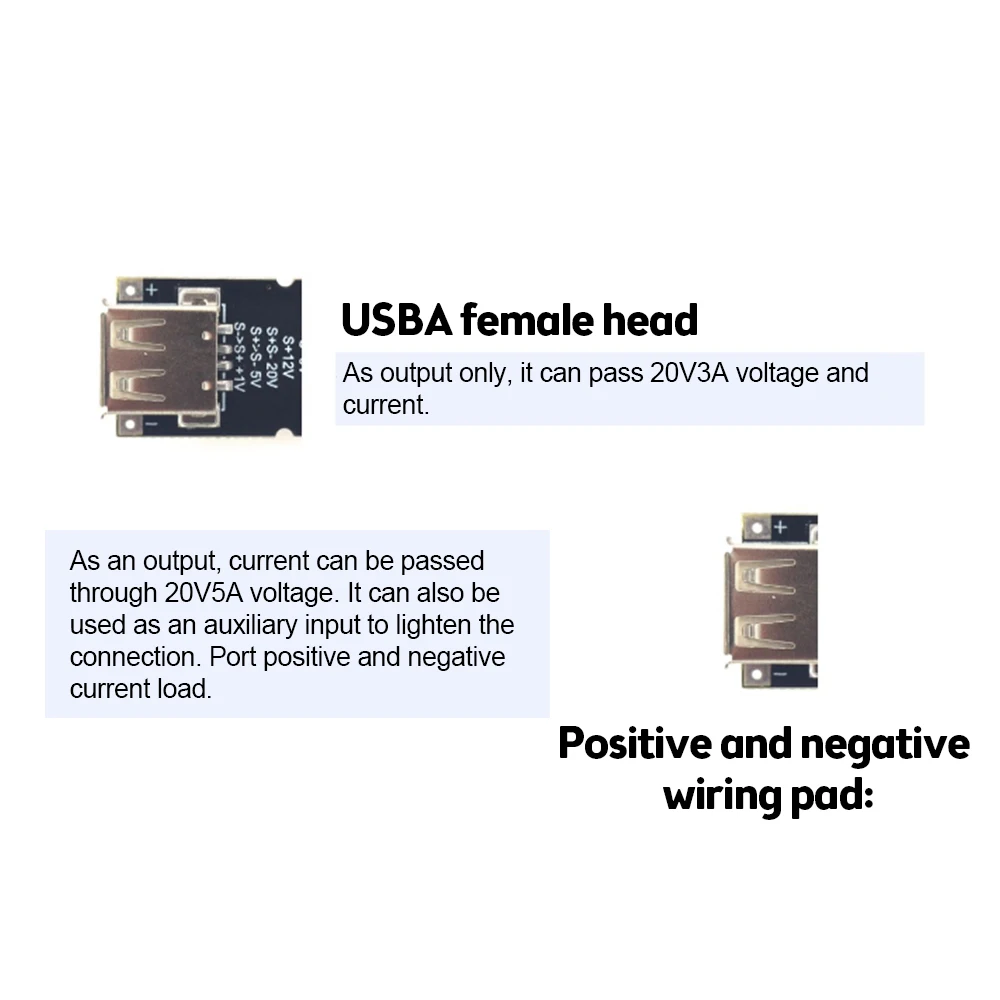
- USB-A Female Interface: As an output, it can pass 20V3A voltage and current.
- Positive and negative wiring pads: as an output interface, it can output 20V 5A voltage and current.


Reviews
There are no reviews yet.