DESCRIPTION
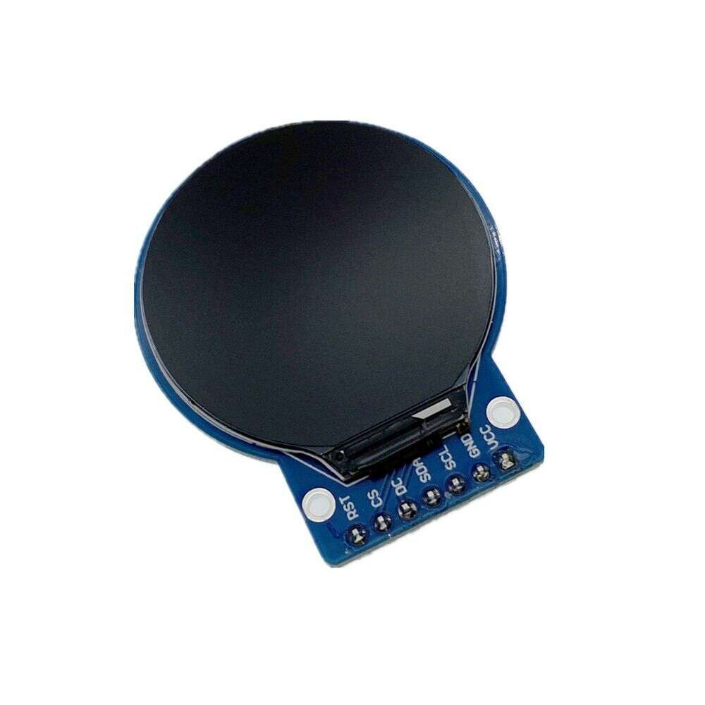
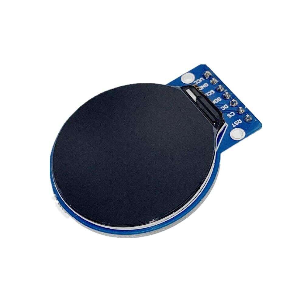
This 1.28″ round LCD is a full color display with a resolution of 240 x 240 pixels.
PACKAGE INCLUDES:
- IPS LCD 1.28″ 240×240 RGB Round Display with GC9A01 driver
KEY FEATURES OF IPS LCD 1.28″ 240×240 DISPLAY WITH GC9A01 DRIVER:
- 1.28″ IPS LCD
- RGB Full color display
- Wide viewing angle
- 240 x 240 high resolution
- SPI interface with CS pin
- GC9A01 LCD display controller
- 3.3V to 5V Vcc power
- 3.3V logic compatible only
These full color displays can pack a lot of information into a small 1.28″ round form factor.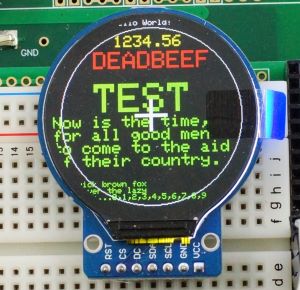
The round modules were originally designed for smart watches and similar applications and provide an interesting change-up from the typical rectangular LCD or OLED modules and work great for making small round gauges of various types or running the Uncanny Eyes application since the round LCDs already look a bit like eyes.
The module can be powered from 3.3V or 5V as it contains a 3.3V regulator, but it is 3.3V logic compatible only. If using with a 5V MCU, be sure to include logic level shifters on the data lines to prevent possible damage.
SPI Interface
This display incorporates the SPI interface which provides for fast display updates.
Since it is a write only device, it does not need the SPI MISO line hooked up. The module does bring the CS pin out to the interface which allows multiple devices to share the same SPI bus.
Module Connections
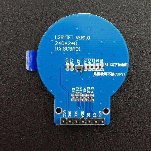
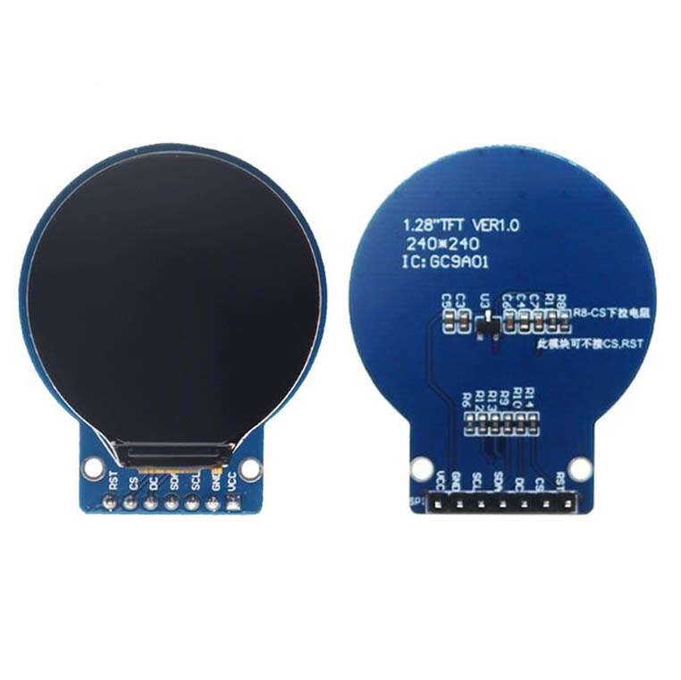
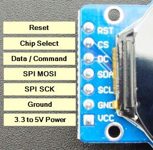 Connection to the display is via a 7-pin header.
1 x 7 Header
- RES – Reset for the GC9A01 LCD controller. Normally HIGH, pull LOW to reset. This display requires a reset to operate correctly.
- CS – Chip Select. Active LOW
- DC – Data / Command. Determines type type of data being sent to the display. LOW = Command, HIGH = Data
- SDA – Connect to SPI MOSI (Data)
- SCL – Connects to SPI SCL (Clock)
- GND – Connect to system ground. This ground needs to be in common with the MCU.
- VCC – Connect to 3.3V or 5V. This can come from the MCU or separate power supply.
OUR EVALUATION RESULTS:
These are interesting modules to work with since they have full color and graphical capability with good library support and come in an interesting round shape.
The display drivers are 240×240 pixels, but obviously the LCDs are not rectangular, so the active pixels are those that fall within a circle that is overlaid over that rectangle.
These modules are breadboard friendly with a 7-pin header on the back that can be inserted into a solderless breadboard or a 7-pin female connector can be used to connect to it if the display is to be mounted. The display is mounted on a thin PCB which helps provide support, but be sure to press on the header pins when applying pressure to insert them into a breadboard and not press on the glass to avoid possible damage.
Though these displays can seem to be a bit intimidating to use at first, just follow these steps to get up and running easily.
Connecting the Display
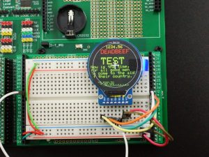 Connect VCC to 3.3V or 5V and GND to ground on the MCU.
Connect the SPI lines. We are using a Teensy 4.1 setup in our example and are using pin 11 for SDA (MOSI) and pin 13 for SCL (SCK). Other MCUs may map their SPI on different pins.
Connect CS to pin 10, DC to pin 9 and RST to pin 8. These are all arbitrary and can be reassigned to any available pins.
If you are using a 3.3V MCU, these lines can be connected directly. If you are using a 5V MCU, then be sure to use a logic level converter.
Install GC9A01A_t3n Library
Install the Teensy GC9A-1A_t3n library if using a Teensy. You will need to manually download it from the GitHub site as it is not available via the Arduino IDE library manager. This library is a modified version of the ILI9341_t3n library and includes updated example programs like the Uncanny Eyes.
https://github.com/mjs513/GC9A01A_t3n
Download and Run Program
The program below is a modified version of the example program graphicstest that is included when the GC9A01A_t3n library is installed. It is pruned way down to show the basic graphics operation of the display.
GC9A01 LCD Test Program
/***************************************************
GC9A01A LCD Display Driver Test

This is a spin on the graphicstest example that works with the
GC9A01A_t3n library for the Teensy products.

It demonstrates basic color, text, rectangle and circle
drawing capability
 ****************************************************/
#include "SPI.h"
#include "GC9A01A_t3n.h"
// *************** Change to your Pin numbers ***************
#define TFT_DC  9
#define TFT_CS 10
#define TFT_RST 8
#define TFT_SCK 13
#define TFT_MOSI 11

GC9A01A_t3n tft = GC9A01A_t3n(TFT_CS, TFT_DC, TFT_RST);

void setup() {
  while (!Serial && millis() < 5000) ; // wait for Arduino Serial Monitor
  Serial.begin(9600);
  delay(500);
  Serial.println("CG9A01A Test");
  tft.begin();
  tft.fillScreen(BLACK); delay(500);
  tft.fillScreen(RED); delay(500);
  tft.fillScreen(GREEN); delay(500);
  tft.fillScreen(BLUE); delay(500);
  tft.fillScreen(BLACK); delay(500);
}

void loop(void) {
  for (uint8_t rotation = 0; rotation < 4; rotation++) {
    tft.setRotation(rotation);
    drawText();
    tft.drawCircle(120, 120, 110, WHITE);
    tft.fillRect(100, 118, 40, 4, WHITE);
    tft.fillRect(118, 100, 4, 40, WHITE);
    delay(3000);
  }
}

unsigned long drawText() {
  tft.fillScreen(BLACK);
  tft.setCursor(75, 0);
  tft.setTextColor(WHITE);  tft.setTextSize(1);
  tft.println("Hello World!");
  tft.setCursor(75,20);
  tft.setTextColor(YELLOW); tft.setTextSize(2);
  tft.println(1234.56);
  tft.setCursor(50,40);
  tft.setTextColor(RED);    tft.setTextSize(3);
  tft.println(0xDEADBEEF, HEX);
  tft.println();
  tft.setCursor(50,80);
  tft.setTextColor(GREEN);
  tft.setTextSize(5);
  tft.println("TEST");
  tft.setTextSize(2);
  tft.println("Now is the time,");
  tft.println("for all good men");
  tft.println("to come to the aid");
  tft.println("of their country.");
  tft.println();
  tft.setTextSize(1);
  tft.println("The quick brown fox");
  tft.println("jumps over the lazy");
  tft.println("dogs back...0,1,2,3,4,5,6,7,8,9");
}
Notes:
- The display is thin and fragile. Ensure you don’t apply pressure directly to the glass or it may damage the display
TECHNICAL SPECIFICATIONS
| Display | Resolution | 240 x 240 pixels |
| Color | RGB Full Color | |
| Interface | SPI | |
| Operating Ratings | DC Power Input | 3.3V to 5V |
| Operating Current (max) | < 48mA | |
| Dimensions | ||
| Module Size (PCB) | 38 x 45.5mm (1.50″ x 1.79″) | |
| Display Diagonal (active) | 32.4mm (1.28″) | |
| Display (W x H) | 32.4 x 32.4mm (1.28 x 1.28″) | |
| Display Controller | GC9A01 |


Reviews
There are no reviews yet.