


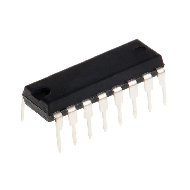

Pin Configuration
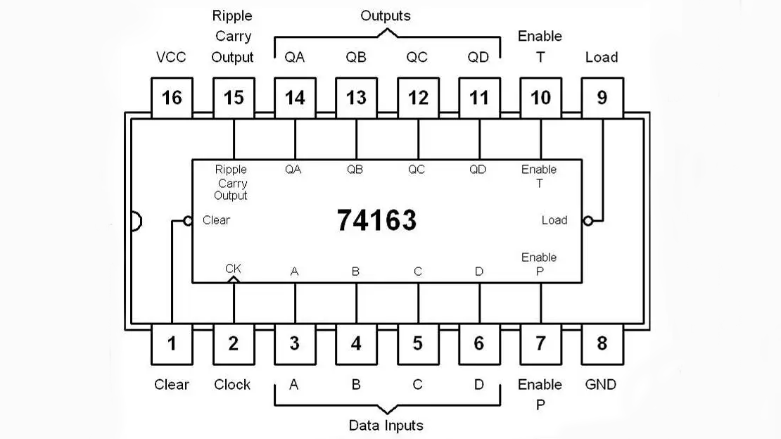
| Pin No. | Symbol | Description |
|---|---|---|
| 1 | CLR | Asynchronous Master Reset (Active LOW) |
| 2 | CLK | Clock Input (Rising Edge Triggered) |
| 3 | A | Parallel Data Input (LSB) |
| 4 | B | Parallel Data Input |
| 5 | C | Parallel Data Input |
| 6 | D | Parallel Data Input (MSB) |
| 7 | ENP | Count Enable Parallel Input |
| 8 | GND | Ground (0V) |
| 9 | LOAD | Synchronous Parallel Load Input (Active LOW) |
| 10 | ENT | Count Enable Trickle Input |
| 11 | QD | Output Bit 3 (MSB) |
| 12 | QC | Output Bit 2 |
| 13 | QB | Output Bit 1 |
| 14 | QA | Output Bit 0 (LSB) |
| 15 | RCO | Ripple Carry Output |
| 16 | VCC | Positive Supply Voltage (+5V) |
Applications
- Digital counters and frequency dividers.
- Sequential logic and state machine designs.
- Digital clocks and timers.
- Frequency and event counting circuits.
- LED or display driving systems.
- Pulse generation and timing control units.
- Binary counting and arithmetic operations in digital systems.
- Microcontroller and digital circuit prototyping.
- Control and sequencing logic in automation systems.
Package Contents
- 1 x 74163 High-Speed CMOS 4-Bit Synchronous Binary Counter DIP-16.


