4511 – A BCD to 7-Segment Display Driver Chip Pinout
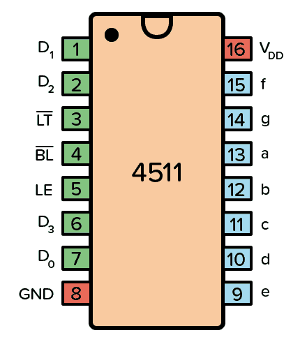
The 4511 is a BCD to 7-segment decoder. It means it takes a number in binary form as an input, then displays this number on a 7-segment display using its outputs.
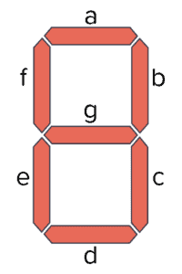
A 7-segment display is a component with seven Light-Emitting Diodes (LED) arranged as shown below. By turning on different combinations of the LEDs, a number between 0 and 9 is displayed.
Pin Overview
| Pin Name | Pin # | Type | Description |
|---|---|---|---|
| VDD | 16 | Power | Supply Voltage (+3 to +15V) |
| GND | 8 | Power | Ground (0V) |
| a-f | 9-15 | Output | Outputs for the 7-segment display |
| D0-D3 | 7, 1, 2, 6 | Input | 4-bit data input |
| LT | 3 | Input | Lamp Test. Turns on all segments when LOW. |
| BL | 4 | Input | Blanking Test. Turns off all segments when LOW. |
| LE | 5 | Input | Latch Enable. Stores the current state when HIGH. |
Technical Specifications
| Product Attribute | Attribute Value |
| Product Category: | Encoders, Decoders, Multiplexers & Demultiplexers |
| Product: | Decoders / Demultiplexers |
| Logic Family: | 4500 |
| Number of Input Lines: | 4 Input |
| Number of Output Lines: | 7 Output |
| Package/Case: | PDIP-16 |
| Propagation Delay Time: | 420 ns |
| Supply Voltage – Min: | 3 V |
| Supply Voltage – Max: | 18 V |
| Mounting Style: | Through Hole |
| Minimum Operating Temperature: | – 55 C |
| Maximum Operating Temperature: | + 125 C |
| High Level Output Current: | – 1.5 mA |
| Low Level Output Current: | 1.5 mA |
| Maximum Clock Frequency: | 8 MHz |
| Operating Supply Voltage: | 3 V to 18 V |
| Product Type: | Encoders, Decoders, Multiplexers & Demultiplexers |
| Series: | CD4511B |
| Subcategory: | Logic ICs |
What is a BCD to 7-Segment Driver?
A 7-segment display driver turns on the correct segments of a 7-segment display according to an input.
In this case, the input is Binary-Coded Decimal (BCD). For example, an input of 1001, which is 9 in decimal, would turn on the segments a, b, c, f, and g so that a “9” is displayed on the 7-segment display:

So, how exactly does this IC convert binary codes to decimal numbers? It does so by using a combination of logic gates and D flip-flops.
From the HEX4511B datasheet, we can find the internal circuit of the 4511:

For each input bit (D0-D3), there is a D latch.
When the EN input of a D latch is HIGH, whatever is on the D input is transferred to the Q output. But when EN goes low, the last input value is stored onto the output Q and cannot change.
This means that when LE is LOW, the segment outputs (a to g) are determined by the data on D0 to D3. But when LE goes HIGH, the last data present on D0 to D3 is stored in the latches and the segment outputs stay unchanged.
The logic gates below convert the bits from the latches into 7-segment output.
How to use CD4511 IC?
To use this IC, you don’t need too many things to connect, just need a toggle or push button to change the logic over the IC input pins and pull down the resistor with them as shown in the circuit. A resistor pack or a few resistors are also needed to connect a 7-segment display. As the setup is complete you just have to follow the table to get the required output number.
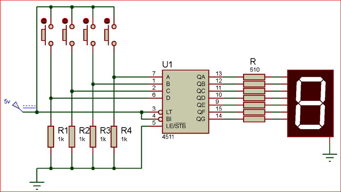
| Displaying decimal number | BCD code | Push buttons | |||
| 0 | 0000 | Low | Low | Low | Low |
| 1 | 0001 | Low | Low | Low | High |
| 2 | 0010 | Low | Low | High | Low |
| 3 | 0011 | Low | Low | High | High |
| 4 | 0100 | Low | High | Low | Low |
| 5 | 0101 | Low | High | Low | High |
| 6 | 0110 | Low | High | High | Low |
| 7 | 0111 | Low | High | High | High |
| 8 | 1000 | High | Low | Low | Low |
| 9 | 1001 | High | Low | Low | High |




Reviews
There are no reviews yet.