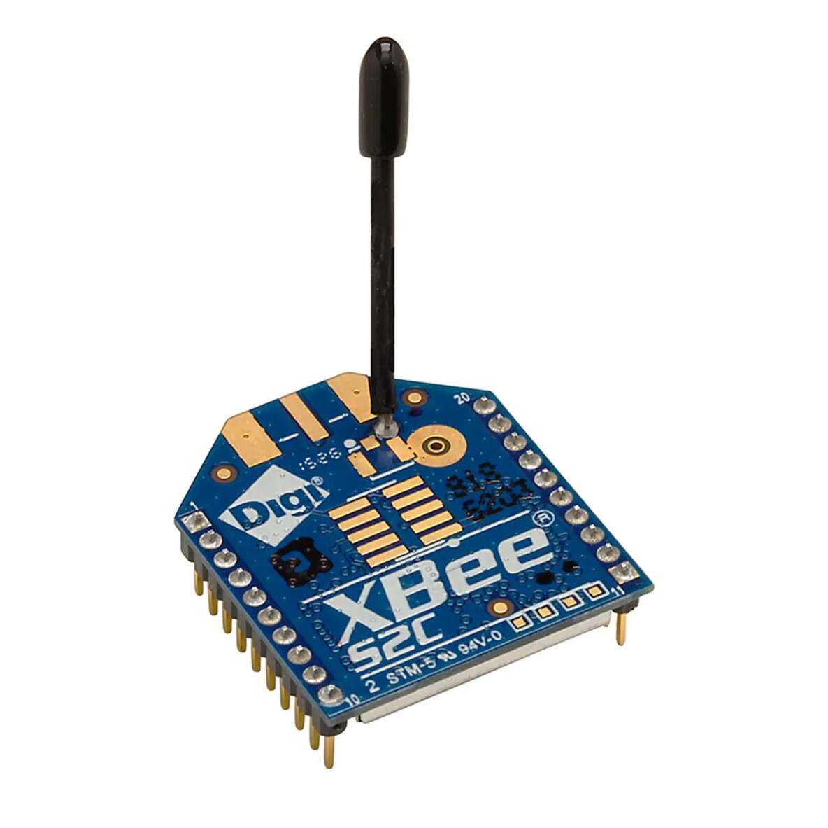
Digi XBee RF modules provide OEMs with a common footprint shared by multiple platforms, including multipoint and ZigBee/ Mesh topologies, and both 2.4 GHz and 900 MHz solutions. OEMs deploying the XBee can substitute one Digi XBee for another, depending upon dynamic application needs, with minimal development, reduced risk and shorter time-to-market.
Digi XBee 802.15.4 RF modules are ideal for applications requiring low latency and predictable communication timing. Providing quick, robust communication in point-to-point, peer-to-peer, and multipoint/star configurations, Digi XBee 802.15.4 products enable robust end-point connectivity with ease. Whether deployed as a pure cable replacement for simple serial communication, or as part of a more complex hub-and-spoke network of sensors, Digi XBee 802.15.4 RF modules maximize performance and ease of development.
XBee 802.15.4 modules seamlessly interface with compatible gateways, device adapters and range extenders, providing developers with true beyond-the-horizon connectivity.
The updated Digi XBee S2C 802.15.4 module is built with the SiliconLabs EM357 SoC and offers improved power consumption, support for over-the-air firmware updates, and provides an upgrade path to DigiMesh® or Zigbee® mesh protocols if desired.
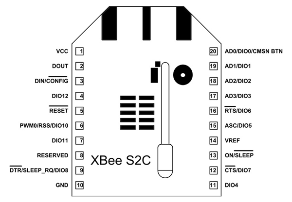
XBee S2C Pin Configuration
XBee S2C is a 20 pin module as given in XBee S2C pinout diagram and the description for each pin is given below.
| Pin | Name | Description |
| 1 | VCC | Power supply |
| 2 | DOUT/DIO13 | UART data out pin (TXD)/GPIO |
| 3 | DIN/CONFIG / DIO14 | UART data in pin (RXD)/ GPIO |
| 4 | DIO12/SPI_MISO | GPIO/ Master Input-Slave Output pin of SPI interface |
| 5 | RESET | Module Reset pin |
| 6 | RSS PWM /DIO10 | RX Signal Strength Indicator pin / GPIO |
| 7 | PWM1/DIO11 | Pulse Width Modulator/GPIO |
| 8 | RESERVED | Do not connect |
| 9 | DTR/SLEEP_RQ/ DIO8 | Pin Sleep Control line /GPIO |
| 10 | GND | Ground |
| 11 | DIO4/ SPI_MOSI | GPIO/Master Output-Slave Input pin of SPI interface |
| 12 | CTS/DIO7 | Clear-to-send flow control/GPIO |
| 13 | ON_SLEEP/DIO9 | Device status indicator/GPIO |
| 14 | VREF | Voltage Reference for ADC |
| 15 | ASC/DIO5 | Associate Indicator/GPIO |
| 16 | RTS/DIO6 | Request to send flow control/ GPIO |
| 17 | AD3/DIO3/SPI_SSEL | Analog input/GPIO/SPI slave select |
| 18 | AD2 /DIO2/SPI_CLK | Analog input/GPIO/SPI clock |
| 19 | AD1/DIO1/SPI_ATTN | Analog input/GPIO/SPI attention |
| 20 | AD0/DIO0/C | Analog input/GPIO/ Commissioning button |
Benefits
- Simple, out-of-the-box RF communications, no configuration needed
- Point-to-multipoint network topology
- 2.4 GHz for worldwide deployment
- Common XBee footprint for a variety of RF modules
- Industry leading sleep current of sub 1uA
- Firmware upgrades via UART, SPI or over the air
- Migratable to DigiMesh and Zigbee PRO protocols and vice-versa
Specifications
| Digi XBee S2C 802.15.4 | |
| PERFORMANCE | |
| TRANSCEIVER CHIPSET | Silicon Labs EM357 SoC |
| DATA RATE | RF 250 Kbps, Serial up to 1 Mbps |
| INDOOR/URBAN RANGE* | Up to 200 ft (60 m) |
| OUTDOOR/RF LINE-OF-SIGHT RANGE* | Up to 4000 ft (1200 m) |
| TRANSMIT POWER | 3.1 mW (+5 dBm) / 6.3 mW (+8 dBm)boost mode |
| RECEIVER SENSITIVITY (1% PER) | -100 dBm / -102 dBm boost mode |
| FEATURES | |
| SERIAL DATA INTERFACE | UART, SPI |
| CONFIGURATION METHOD | API or AT commands, local or over-the-air (OTA) |
| FREQUENCY BAND | ISM 2.4 GHz |
| FORM FACTOR | Through-Hole, Surface Mount |
| HARDWARE | S2C |
| ADC INPUTS | (4) 10-bit ADC inputs |
| DIGITAL I/O | 15 |
| ANTENNA OPTIONS | Through-Hole: PCB Antenna, U.FL Connector, RPSMA Connector, or Integrated Wire SMT: RF Pad, PCB Antenna, or U.FL Connector |
| OPERATING TEMPERATURE | -40º C to +85º C |
| DIMENSIONS (L X W X H) AND WEIGHT | Through-Hole: 0.960 x 1.087 in (2.438 x 2.761 cm) SMT: 0.866 x 1.33 x 0.120 in (2.199 x 3.4 x 0.305 cm) |
| NETWORKING AND SECURITY | |
| PROTOCOL | XBee 802.15.4 (Proprietary 802.15.4) |
| UPDATABLE TO DIGIMESH PROTOCOL | Yes |
| UPDATABLE TO ZIGBEE PROTOCOL | Yes |
| INTERFERENCE IMMUNITY | DSSS (Direct Sequence Spread Spectrum) |
| ENCRYPTION | 128-bit AES |
| RELIABLE PACKET DELIVERY | Retries/Acknowledgements |
| FILTRATION OPTIONS | PAN ID, Channel, and 64-bit addresses |
| CHANNELS | 16 channels |
| POWER REQUIREMENTS | |
| SUPPLY VOLTAGE | 2.1 to 3.6V |
| TRANSMIT CURRENT | 33 mA @ 3.3 VDC / 45 mA boost mode |
| RECEIVE CURRENT | 28 mA @ 3.3 VDC / 31 mA boost mode |
| POWER-DOWN CURRENT | <1 μA @ 25º C |




Reviews
There are no reviews yet.