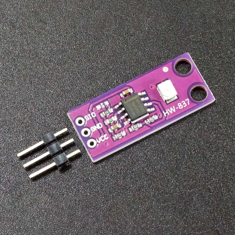
The GUVA-S12SD UV Light Sensor Module is an analog UV light to voltage converter for measuring the intensity of UV light.
PACKAGE INCLUDES:
- GUVA-S12SD UV Light Sensor Module
- 3-pin male header
KEY FEATURES OF GUVA-S12SD UV LIGHT SENSOR MODULE:
- Detects UV light in the 240nm – 370nm range
- Analog voltage output proportional to the UV Index of UV light falling on the detector
- 3.3 and 5V compatible
The GUVA-S12SD is a true UV detector that only detects light from 240nm to 370nm which is the UV-B and most of the UV-A spectrum. It also picks up the upper end of UV-C.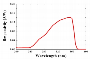
These wavelengths are used in black lights, tanning beds, reptile UV emitters, germicidal sterilizers and similar applications. The device can be used to monitor the operation of those devices.
It can also be used to measure the UV Index which provides a scale to determine how intense the sun UV is and therefore what kind of protective measures should be taken.
The UV Index scale is published by the EPA and intended to give guidance to people on sun exposure and what protective measures to take to minimize damage from the sun.

More info on the UV Index scale can be found at the link in Further Reading down below.
Theory of Operation
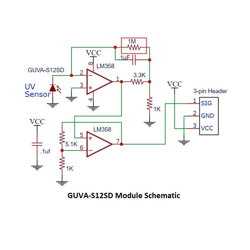
The module includes an LM358 dual op amp which converts the current output of the sensor to a voltage and then amplifies that output so that it can be read by the analog input on an MCU for taking UV readings.
The first stage op amp outputs a voltage proportional to 4.3 * sensor photocurrent in µA. If the photocurrent is 0.1µA (0.09mW/cm^2), then the output will be 0.43V
This feeds a second stage op amp with an additional gain of 6.1x. In this example the final output will be 0.43V x 6.1 = 2.62V.
As configured, the module is mainly useful for measuring moderate to moderately high UV light levels or if the sensor is placed behind a neutral density filter to reduce the percentage of UV striking the sensor.
If it is desired to measure very high UV levels, the second stage of amplification can be bypassed. This can be accomplished by shorting across the 5.1K resistor “512”and removing the 1K resistor to the right of it with marking “01B” or “102”. This changes the gain of the output op amp to x1 effectively taking it out of circuit. With that modification, UV index is then calculated by multiplying the output by 10.
Please note: As of 6/2021, we are modifying this module and it now ships with a 1M feedback resistor on the first stage as noted above. Prior to that date, the feedback resistor was 10M. 10M resistors are marked 01F, 1M resistors are marked 01E. With a 10M feedback resistor, the first stage is 43 * sensor photocurrent in µA. If the photocurrent is 0.1µA (0.09mW/cm^2), then the output will be 4.3V.
Module Connections
The module brings out the following connections.
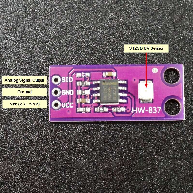
1 x 3 Header
- SIG or SIO = Signal Output – Connect to MCU analog input
- GND = Ground
- VCC = 2.7V to 5.5V. Connect to Vcc of the MCU (typically 3.3 or 5V)
Module Assembly
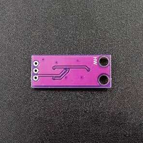
The module ships with the male header strip loose. The header can be soldered to the top or bottom of the module depending on the planned use or wires can be used to make the connections.
For breadboard use, we put the headers on the bottom. Soldering is easiest if the header is inserted into a solderless breadboard to hold it in position during the soldering process.
OUR EVALUATION RESULTS:

The program below simply reads the output of the sensor every second and prints the raw reading and UV Index to the Serial Monitor window.
To use this program you will want a source of UV which can be the sun or something like a black light as shown in the picture to the right. The nice thing about a black light is that by changing the distance to the sensor, you can see that the output of the sensor changes to match the intensity of the UV falling upon the sensor.
The sensor is connected to analog pin A0, but this can be changed to any convenient analog input. Also be sure to provide power and ground. We are using 5V in this example.
GUVA-S12SD UV Light Sensor Example Program
/*
   GUVA-S12SD UV Light Meter Program

  Simple program to read the analog output of the sensor and display
  the raw voltage output reading

  We are connecting sensor to analog input A0, but this can be any analog pin.
*/
int const UV_SENSOR_PIN = A0;
//===============================================================================
//  Initialization
//===============================================================================
void setup() {
  Serial.begin(9600);    // Initialize serial comm
}
//===============================================================================
//  Main
//===============================================================================
void loop() {

  int sensor_value = analogRead(UV_SENSOR_PIN); // Get raw sensor reading
  float volts = sensor_value * 5.0 / 1024.0;
  Serial.print ("Sensor Voltage Output: ");
  Serial.print (sensor_value);

  delay(1000);  // Take reading every second
}
TECHNICAL SPECIFICATIONS
| Operating Ratings | ||
| Vcc Range | 2.7 – 5.5V (3.3 or 5V Typical) | |
| Spectral Detection | Detection Range | 240nm-370nm |
| Dimensions | L x W (PCB) | 28 x 12mm |
| Datasheet | GenUV | GUVA-S12SD |
FURTHER READING
Wikepdia: https://en.wikipedia.org/wiki/Ultraviolet
EPA UV Index Scale: https://www.epa.gov/sunsafety/uv-index-scale-1