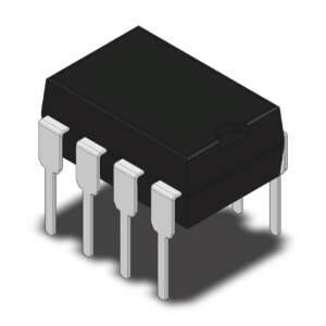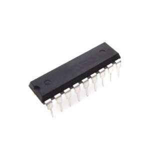







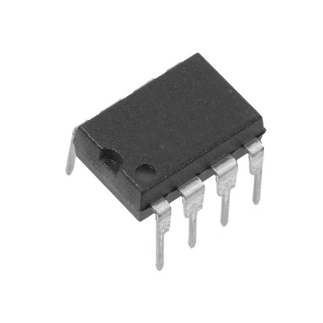
IR2117 High-Voltage High-Speed Single-Channel Gate Driver IC 600V DIP-8
IR2117 600V high-voltage, high-speed single-channel MOSFET/IGBT gate driver, 10-20V, 200mA source/420mA sink, in-phase output, 8-pin PDIP.
70.00 EGP
Buy NowIR2117 High-Voltage High-Speed Single-Channel Gate Driver IC 600V DIP-8
The IR2117 is a high-voltage, high-speed power MOSFET and IGBT driver. Proprietary HVIC and latch-immune CMOS technologies enable ruggedized monolithic construction. The logic input is compatible with standard CMOS outputs.
Features
- Floating channel designed for bootstrap operation
- Tolerant to negative transient voltage
- Gate drive supply range from 10V to 20V
- CMOS Schmitt-triggered inputs with pull-down
- Output in phase with input
- High pulse current buffer stage designed for minimum cross-conduction
- Logic input compatible with standard CMOS outputs
- Single-channel driver
Specifications
| Parameter | Value | Conditions / Notes |
|---|---|---|
| General | ||
| Product Type | High-voltage, high-speed power MOSFET and IGBT driver | Single channel |
| Part Number | IR2117 | 8-lead PDIP package |
| Lead-Free Part Number | IR2117PbF | Lead-free version |
| Output Phase | Output in phase with input | IR2117 specific |
| Input Type | CMOS Schmitt-triggered input with pull-down | Logic input compatible with standard CMOS outputs |
| Output Driver | High pulse current buffer stage | Designed for minimum cross-conduction |
| Floating Channel | Designed for bootstrap operation | Can be used to drive an N-channel power MOSFET or IGBT in high or low side configuration |
| Key Ratings | ||
| VOFFSET | 600V max | High-side floating supply offset voltage |
| Gate Drive Supply Range | 10V to 20V | From datasheet features and product summary |
| Output High Short-Circuit Pulsed Current (IO+) | 200mA min, 250mA typ | VO = 0V, VIN = Logic “1”, PW ≤ 10µs |
| Output Low Short-Circuit Pulsed Current (IO-) | 420mA min, 500mA typ | VO = 15V, VIN = Logic “0”, PW ≤ 10µs |
| Turn-On Propagation Delay, ton | 125ns typ, 200ns max | VS = 0V |
| Turn-Off Propagation Delay, toff | 105ns typ, 180ns max | VS = 600V |
| Turn-On Rise Time, tr | 80ns typ, 130ns max | Dynamic switching characteristic |
| Turn-Off Fall Time, tf | 40ns typ, 65ns max | Dynamic switching characteristic |
| Dynamic Test Conditions | VBIAS (VCC, VBS) = 15V; CL = 1000pF; TA = 25°C | Unless otherwise specified |
| Recommended Operating Conditions | ||
| VB, High-Side Floating Supply Voltage | VS + 10V to VS + 20V | Recommended operating condition |
| VS, High-Side Floating Supply Offset Voltage | 600V max | Logic operational for VS of -5V to +600V; logic state held for VS of -5V to -VBS |
| VHO, High-Side Floating Output Voltage | VS to VB | Recommended operating condition |
| VCC, Logic Supply Voltage | 10V to 20V | Recommended operating condition |
| VIN, Logic Input Voltage | 0V to VCC | Recommended operating condition |
| Ambient Temperature, TA | -40°C to +125°C | Recommended operating condition |
| Allowable Offset Supply Voltage Transient, dVs/dt | 50 V/ns | Maximum rating |
| Static Electrical Characteristics | ||
| Input Logic “1” Voltage, VIH | 9.5V min | IR2117 logic “1” |
| Input Logic “0” Voltage, VIL | 6.0V max | IR2117 logic “0” |
| High-Level Output Voltage Drop, VBIAS – VO | 100mV max | IO = 0A |
| Low-Level Output Voltage, VOL | 100mV max | IO = 0A |
| Offset Supply Leakage Current, ILK | 50µA max | VB = VS = 600V |
| Quiescent VBS Supply Current, IQBS | 50µA typ, 240µA max | VIN = 0V or VCC |
| Quiescent VCC Supply Current, IQCC | 70µA typ, 340µA max | VIN = 0V or VCC |
| Logic “1” Input Bias Current, IIN+ | 20µA typ, 40µA max | VIN = VCC |
| Logic “0” Input Bias Current, IIN- | 1.0µA max | VIN = 0V |
| VBS Undervoltage Positive-Going Threshold, VBSUV+ | 7.6V min, 8.6V typ, 9.6V max | VBS supply undervoltage threshold |
| VBS Undervoltage Negative-Going Threshold, VBSUV- | 7.2V min, 8.2V typ, 9.2V max | VBS supply undervoltage threshold |
| VCC Undervoltage Positive-Going Threshold, VCCUV+ | 7.6V min, 8.6V typ, 9.6V max | VCC supply undervoltage threshold |
| VCC Undervoltage Negative-Going Threshold, VCCUV- | 7.2V min, 8.2V typ, 9.2V max | VCC supply undervoltage threshold |
| Absolute Maximum Ratings | ||
| VB, High-Side Floating Supply Voltage | -0.3V to 625V | Absolute maximum rating |
| VS, High-Side Floating Supply Offset Voltage | VB – 25V to VB + 0.3V | Absolute maximum rating |
| VHO, High-Side Floating Output Voltage | VS – 0.3V to VB + 0.3V | Absolute maximum rating |
| VCC, Logic Supply Voltage | -0.3V to 25V | Absolute maximum rating |
| VIN, Logic Input Voltage | -0.3V to VCC + 0.3V | Absolute maximum rating |
| Junction Temperature, TJ | 150°C max | Absolute maximum rating |
| Storage Temperature, TS | -55°C to +150°C | Absolute maximum rating |
| Lead Temperature | 300°C max | Soldering, 10 seconds |
| Package and Thermal Data (8-Pin PDIP) | ||
| Package Type | 8-Lead PDIP | Through-hole package |
| Package Power Dissipation, PD | 1.0W | TA ≤ +25°C |
| Thermal Resistance, Junction-to-Ambient, RthJA | 125°C/W | Board-mounted, still-air conditions |

Applications
- High-voltage, high-speed power MOSFET gate driving
- High-voltage, high-speed IGBT gate driving
- N-channel power MOSFET or IGBT drive in high-side configuration
- N-channel power MOSFET or IGBT drive in low-side configuration
Package Content
- 1 x IR2117 High-Voltage High-Speed Single-Channel Gate Driver IC 600V DIP-8
DataSheet
Related products