




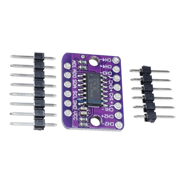
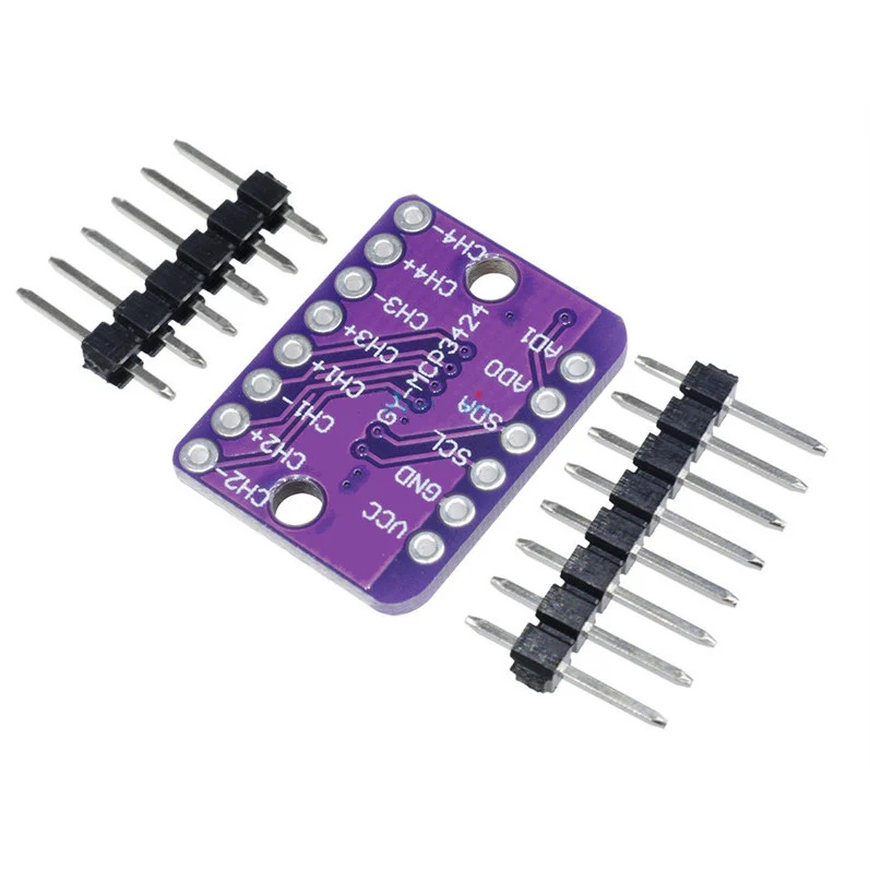
MCP3424 18-Bit ADC – 4 Channel with Programmable Gain Amplifier Breakout Board
MCP3424 18-bit 4-channel ADC breakout board with I²C interface, programmable gain amplifier, differential inputs, and up to 18-bit resolution.
1,300.00 EGP
In stockSKU 3496300153169
Buy Now
Shipping across EgyptDelivered to your door
Cash on deliveryPay when your order arrives
Not sure it fits your project?Ask us on WhatsApp - we reply fast
MCP3424 18-Bit ADC – 4 Channel with Programmable Gain Amplifier Breakout Board
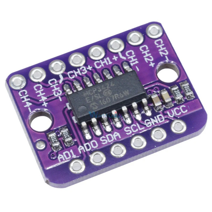
The MCP3424 18-Bit ADC – 4 Channel with Programmable Gain Amplifier Breakout Board is a high-precision analog-to-digital converter module designed for applications requiring accurate low-noise signal measurement. Based on the MCP3424, it features four differential analog input channels, an integrated Programmable Gain Amplifier (PGA), and communicates through a simple I²C interface, making it ideal for Arduino, ESP32, Raspberry Pi, STM32, and other embedded platforms.
Features:
- High-precision 18-bit Delta-Sigma ADC
- 4 differential analog input channels
- Built-in Programmable Gain Amplifier (PGA)
- Programmable gain settings: ×1, ×2, ×4, ×8
- I²C communication interface
- Integrated 2.048V precision voltage reference
- Programmable resolutions: 12, 14, 16, and 18 bits
- Programmable conversion rates
- One-shot and continuous conversion modes
- Self-calibration for offset and gain
- Low power consumption
Specifications:
| Parameter | Value |
|---|---|
| Model | MCP3424. |
| Resolution | 12/14/16/18-Bit (Programmable). |
| Input Channels | 4 Differential. |
| ADC Type | Delta-Sigma (ΔΣ). |
| Reference Voltage | 2.048V (On-Board). |
| Reference Accuracy | ±0.05%. |
| Reference Drift | 15ppm/°C. |
| PGA Gain Options | 1, 2, 4, 8. |
| Input Range | -VREF to +VREF. |
| INL | 10ppm of FSR. |
| Gain Error | 0.05% (PGA=1, 18-bit). |
| Offset Error | 15µV (PGA=1, 18-bit). |
| Data Rate (12-bit) | 240SPS. |
| Data Rate (14-bit) | 60SPS. |
| Data Rate (16-bit) | 15SPS. |
| Data Rate (18-bit) | 3.75SPS. |
| Interface | I2C. |
| I2C Speed | 100kHz/400kHz/3.4MHz. |
| I2C Addresses | 8 (Selectable via AD0, AD1). |
| Operating Voltage | 2.7V-5.5V. |
| Continuous Current | 135µA (VDD=3V, Typical). |
| One-Shot Current | 36µA (VDD=3V, 1SPS, Typical). |
| Operating Temperature | -40°C to +125°C. |
| Pin Spacing | 2.54mm. |
| Package | SOIC-14 (Breakout). |
| Length | 20.5mm. |
| Width | 15.5mm. |
| Height | 3mm. |
Pin Configuration:

| Pin Position | Pin Name | Function/Description |
|---|---|---|
| Left Column (Top to Bottom) | ||
| Top | VCC | Positive Supply Voltage (2.7V-5.5V). |
| GND | Ground (0V). | |
| SCL | I2C Serial Clock (Input). | |
| SDA | I2C Serial Data (Bidirectional). | |
| AD0 | I2C Address Select Bit 0. | |
| Bottom | AD1 | I2C Address Select Bit 1. |
| Right Column (Top to Bottom) | ||
| Top | CH2- | Channel 2 Negative Differential Input. |
| CH2+ | Channel 2 Positive Differential Input. | |
| CH1- | Channel 1 Negative Differential Input. | |
| CH1+ | Channel 1 Positive Differential Input. | |
| CH3+ | Channel 3 Positive Differential Input. | |
| CH3- | Channel 3 Negative Differential Input. | |
| CH4+ | Channel 4 Positive Differential Input. | |
| Bottom | CH4- | Channel 4 Negative Differential Input. |
Applications:
- Precision Voltage Measurement
- Sensor Data Acquisition
- Load Cell Interfaces
- Pressure Sensors
- Strain Gauge Measurement
- RTD & Thermistor Measurement
- Thermocouple Applications
- Industrial Automation
- Battery Monitoring
- Weighing Systems
- Arduino Projects
- ESP32 Projects
- Raspberry Pi Projects
Package Include:
- 1x MCP3424 18-Bit ADC – 4 Channel with Programmable Gain Amplifier Breakout Board
- 2x pin header straight(6pin, 8pin)
Documents:
Related products

Hot

Hot
Hot