UNI-T UTL8512B+ Programmable DC Electronic Load
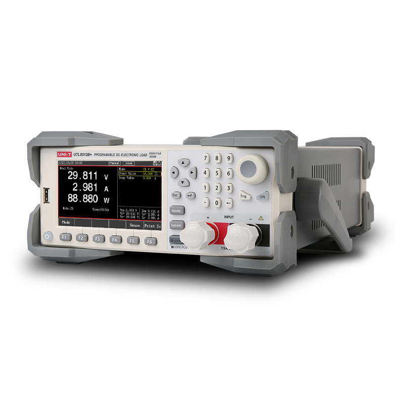
The UNI-T UTL8512B+ Programmable DC Electronic Load is a cost-effective programmable DC electronic load series with high performance. With a resolution of 0.1mV and 0.1mA, multiple protection mechanisms significantly improve the reliability of the equipment. The Series has a variety of testing functions and modes, equipped with RS-232 communication interface, and can be equipped with other communication interfaces according to design and testing requirements. The Series provides a flexible, fast and effective solution. Meet different customers’ needs from Education, Scientific Research and Manufacturing.
Features
- 500 V / 30 A / up to 400 W load capacity.
- Multiple operation modes: CC, CV, CR, CP.
- Synchronous sampling of 500 kHz, 10Hz, 10uA, 0.1 mV stable resolution output.
- Measuring range: voltage of 0~150V/500V, current of 0~15A/30A-40A/120A, power of 150W-600W.
- Dynamic mode (DYNA) of 50 kHz pull load, the waveform of current and voltage peak can be observed directly (UTL8500X+ series), Vpp, Ipp measurement.
- Realistic simulation of LED function.
- Supports OCP test and maximum power test.
- Supports time measurement (TIME).
- Supports OVP test.
- Supports intelligent and programmable automated list test (LIST).
- Protections of over-voltage/under-voltage/over-current/over-power/overheat/anti-reverse connection.
- 4.3 inch LCD, all the test results at a glance.
- Screenshot function with list storage & recall.
- Equipped with standard RS-232 interface and support more extension interfaces.
- Remote sense terminals for accurate voltage measurement.
- Compact ½ 2U rack-mount design.
Specifications
| Parameter | Value |
|---|---|
| Voltage (Input Voltage) | 0–50V / 0–500V |
| Voltage (CV Range) | 0.1–500V |
| Voltage (CV Resolution) | 1mV |
| Voltage (CV Accuracy) | ±(0.03% + 0.05%FS) |
| Voltage (Readback Range) | 0–50V / 0–500V |
| Voltage (Readback Resolution) | 0.01mV / 0.1mV |
| Voltage (Readback Accuracy) | ±(0.02% + 0.3%FS) |
| Current (Input Current) | 0–3A / 0–30A |
| Current (CC Range) | 0–3A / 0–30A |
| Current (CC Resolution) | 0.01mA / 0.1mA |
| Current (CC Accuracy) | ±(0.03% + 0.05%FS) |
| Current (Readback Range) | 0–3A / 0–30A |
| Current (Readback Resolution) | 0.01mA / 0.1mA |
| Current (Readback Accuracy) | ±(0.03% + 0.05%FS) |
| Modes (CR Range) | 0.05Ω–10kΩ |
| Modes (CR Resolution) | 16-bit |
| Modes (CR Accuracy) | (0.1 + 0.01R)% |
| Modes (CP Range) | 400W |
| Modes (CP Resolution) | 10mW |
| Modes (CP Accuracy) | ±(0.1% + 0.1%FS) |
| Modes (Dynamic T1 & T2) | 10µs – 50s |
| Modes (Dynamic Accuracy) | 1µs / 1ms ±100ppm |
| Modes (Dynamic Slope) | 0.0006 A/µs – 3 A/µs |
| Protections (Overpower) | ≥404W (delay), ≥440W (immediate) |
| Protections (Overcurrent) | ≥30.3A (delay), ≥33A (immediate) |
| Protections (Overvoltage) | ≥505V (delay), ≥550V (immediate) |
| Protections (Over-temperature) | ≥85°C |
| Protections (Short Circuit CC) | ≤3A / ≤30A |
| Protections (Short Circuit CV) | 0V |
| Protections (Short Circuit CR) | 120mΩ |
| Power Requirement | 110V / 220V, 50/60Hz |
| Protocol | SCPI |
| Interface | RS232 |
| Dimensions (W×H×D) | 215mm × 88mm × 375 mm |
| Weight | 4.49 kg |
| Display | LCD |
| Input Power | 400W |
| Minimum Operating Voltage | 2.8V ±0.2V @ 30A |
| Readback Power (Range) | 400W |
| Readback Power (Resolution) | 10mW |
| Readback Power (Accuracy) | ±(0.1% + 0.1%FS) |
| Input Terminal Resistance | 1MΩ |
| Fuse | 0.5A (110V) / 0.25A (220V) |
| Ripple Display | Supported |
| Waveform Record | Supported |
| Test Modes | CC, CV, CR, CP, Dynamic, OVP, Time, OCP, CR-LED, Battery, Auto list, Short circuit, Load effect, Combination |
Applications
- Signal distribution in RF and microwave communication systems.
- Use as a broadband transformer in impedance matching networks.
- Integration in RF test and measurement equipment.
- Application in balanced-to-unbalanced signal conversion circuits.
- Use in wireless infrastructure such as base stations and repeaters.
- Incorporation in radar and satellite communication systems.
- Deployment in laboratory prototyping and RF design validation setups.
- Use in audio and high-frequency signal isolation circuits.
- Integration into cable television and broadband distribution networks.
- Application in instrumentation requiring wideband signal coupling.