



LM35 vs DS18B20: How to Choose the Right Temperature Sensor for Your Project?

LM35 vs DS18B20: How to Choose the Right Temperature Sensor for Your Project?
Contents List
- Introduction of Temperature Sensors.
- Types of Temperature Sensors.
- Semiconductor Sensors.
- LM35 Temperature Sensor.
- What Is the LM35?
- LM35 Package Types.
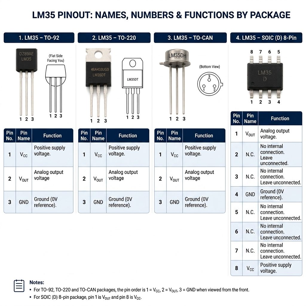
- LM35 Pinout.
- Internal Circuitry of the LM35.
- How Does the LM35 Work?
- LM35 Specifications.
- Equivalents & Alternatives for LM35.
- Advantages of the LM35.
- Limitations of the LM35.
- Common Applications of the LM35.
- Interfacing LM35 with Arduino.
- Arduino Example – Reading Temperature with LM35.
- Practical Projects using LM35.
- DS18B20 Temperature Sensor.
- What Is the DS18B20 ?
- DS18B20 Package Types.
- DS18B20 Pinout.
- Internal Circuitry of the DS18B20.
- DS18B20 Power Modes.
- How Does the DS18B20 Work?
- DS18B20 Specifications.
- Equivalents & Alternatives of DS18B20.
- Advantages of the DS18B20.
- Limitations of the DS18B20.
- Common Applications of the DS18B20.
- Interfacing DS18B20 with Arduino.
- Example waterproof DS18B20 probe with Arduino.
- Practical projects Using DS18B20.
- Comparisons between LM35 and DS18B20.
- Frequently Asked Questions.
- Conclusion.
Reading Time Approximately is 20 minute
Introduction of Temperature Sensors
Temperature is the most often-measured environmental quantity. This might be expected since most physical, electronic, chemical, mechanical, and biological systems are affected by temperature. Certain chemical reactions, biological processes, and even electronic circuits perform best within limited temperature ranges. Temperature is one of the most commonly measured variables and it is therefore not surprising that there are many ways of sensing it. Temperature Sensing can be done either through direct contact with the heating source or remotely, without direct contact with the source using radiated energy instead. There are a wide variety of temperature sensors on the market today, including Thermocouples, Resistance Temperature Detectors (RTDs), Thermistors, Infrared and Semiconductor Sensors.
A precision IC Temperature Sensor is a solid-state, small device that measures temperature with a two-terminal IC, generating an output voltage or current that is proportional to the total temperature. These temperature sensor ICs are mainly designed to measure temperature because they usually work as a voltage output or temperature-dependent current source, with the output signal directly associated with the measured temperature. Examples of these temperature sensor ICs are: LM34 IC, the LM35 IC, and Other IC sensors. This article elaborates on the LM35 sensor IC, its working, and its applications.
Types of Temperature Sensors
- Thermocouple.
- RTD.
- Thermistors.
- Semiconductor Sensors.
Semiconductor Sensors
Temperature sensors can be classified basically under two categories: analog and digital, with the measure of temperature that both of them obtain certainly differing. However, these temperature detectors differ considerably in their working, output, and applications.
Analog Temperature Sensors:
- Output: Produces a continuous signal (voltage or current) proportional to the measured temperature.
- Working: Requires additional circuitry, such as amplifiers and ADCs, to process the signal.
- Accuracy: This may require frequent calibration to maintain accuracy.
- Applications: Common in simple systems where digital processing is unnecessary.
Digital Temperature Sensors:
- Output: Provides a digital signal that can be directly processed by microcontrollers or computers.
- Working: Integrates ADC and signal processing within the sensor, reducing the need for external components.
- Accuracy: Offers high precision and stability with built-in calibration features.
- Applications: Used in advanced systems requiring precise and reliable temperature monitoring, such as IoT Devices, Medical equipment, and Automotive systems.
Important Note:
“analog” and “digital” describe the sensor’s output/interface, not necessarily the underlying sensing technology. Both can use semiconductor-based sensing elements internally.
LM35 Temperature Sensor
What Is the LM35?
The LM35 is a precision analog temperature sensor designed to measure temperature directly in degrees Celsius. It produces an analog output voltage that changes linearly with the measured temperature, making it easy to interface with microcontrollers such as Arduino and other development boards.
Unlike a digital temperature sensor, the LM35 does not send temperature data through a communication protocol. Instead, its Vout pin generates a voltage proportional to the temperature. The sensor has a sensitivity of approximately 10 mV/°C, meaning that the output voltage increases by about 10 mV for every 1°C increase in temperature.
This simple voltage-to-temperature relationship makes the LM35 particularly useful for beginners learning about analog sensors, ADCs, and microcontroller-based measurement systems.
LM35 Package Types
The LM35 is available in several package shapes, depending on the specific LM35 variant:
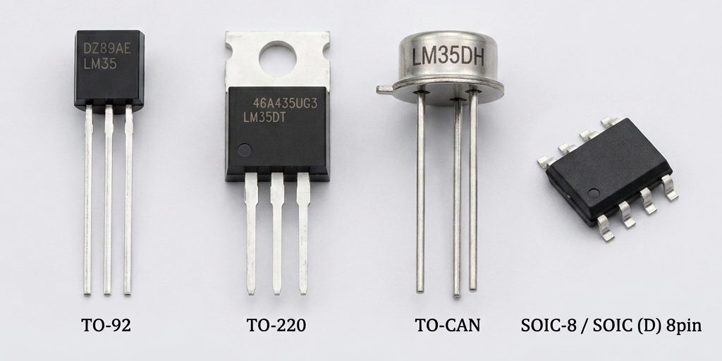
LM35 Pinout
Internal Circuitry of the LM35
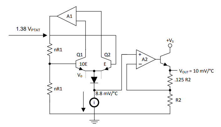
Although the LM35 looks like a simple three-pin transistor-style component, it contains several functional circuits inside its package.
Temperature-Sensitive Circuit
The sensing section uses semiconductor junction characteristics that vary with temperature. These changes provide the electrical information required to determine the temperature.
Differential Amplifier
The internal amplifier processes the small temperature-dependent signal and helps produce the sensor’s linear output.
Voltage Reference and Calibration Circuitry
Internal circuitry establishes the appropriate operating point and helps maintain the specified temperature-to-voltage relationship.
Output Buffer
The output stage provides the analog signal at the Vout pin and allows the sensor to interface with an analog input of a microcontroller.
The internal design allows the LM35 to provide a factory-calibrated output without requiring the user to perform a separate calibration procedure for normal applications.
How Does the LM35 Work?
LM35 sensor works on the diode principle, which means that whenever the temperature increases, the voltage across a diode will increase at a known rate. So, by accurately amplifying the change in voltage, it is simple to produce an analog signal that is directly proportional to temperature. The internal structure of the LM35 sensor is shown below. This sensor includes two transistors, where one transistor has 10 times the emitter region of the other. So it has one-tenth of the current supply density, as a similar current is flowing throughout both transistors. This causes a voltage supply across the R1 resistor that is proportional to the total temperature.
This IC has an amplifier located at the top side, which ensures the voltage supply at the base terminal of the left Q1 transistor is proportional to the total temperature by comparing the two transistors’ output. So the right-side amplifier changes the total temperature into either Celsius or Fahrenheit.
For every 1°C increase in temperature, the Vout pin produces exactly 10mV higher output. This makes the relationship between temperature and voltage very straightforward:
Output Voltage = Temperature (°C) × 10mV
For example:
At 0°C → Output = 0mV
At 25°C → Output = 250mV
At 100°C → Output = 1000mV (1V)
Since the output is a clean analog voltage, a microcontroller like Arduino simply reads it through an ADC (Analog to Digital Converter) pin and converts it back to a temperature value using a simple formula.
LM35 Specifications
| Parameter | Details |
| Sensor Type | Analog temperature sensor. |
| Output Type | Analog voltage. |
| Supply Voltage | 4 V to 30 V. |
| Supply Current | 60 µA typical. |
| Quiescent Current | 56 µA typical. |
| Temperature Range | −55°C to +150°C. |
| Sensitivity | 10 mV/°C. |
| Accuracy | ±0.5°C at 25°C. |
| Output Voltage Range | Approximately −550 mV to +1500 mV. |
| Load Current | 1 mA maximum. |
| Response Time | Approximately 1 second in still air. |
| Storage Temperature | −60°C to +155°C. |
| Available Package Types | TO-92 / TO-220 / TO-CAN / SOIC-8 |
Note:
These values are based on the technical information presented in the Pinout Hub reference; for production designs, the exact part-number datasheet should be used as the final authority.
Equivalents & Alternatives for LM35
Equivalent LM35 sensors are:
LM34, DS1620, DS18B20, LM94022, etc.
Alternative temperature sensors are:
DHT11, LM35, DHT22, DS18B20, BMP180, BME280, etc.
Advantages of the LM35
- Linear output: The output voltage changes predictably with temperature.
- Simple interface: It can be connected directly to an analog input.
- Low current consumption: Typical current consumption is around 60 µA.
- Wide measurement range: Suitable for temperatures from −55°C to +150°C.
- Easy temperature conversion: The 10 mV/°C sensitivity makes calculations straightforward.
- Low self-heating: Low power consumption helps minimize the sensor’s influence on the measured temperature.
- Compact package: Available in several small package options.
Limitations of the LM35
- The LM35 is a simple and useful sensor, but its analog output also introduces some considerations.
- Because the temperature information is transmitted as a voltage, the reading can be affected by the microcontroller’s ADC resolution, reference voltage, electrical noise, and wiring. The source document also identifies limited resolution, relatively slow response, and susceptibility to noise as potential disadvantages.
- For applications that require digital communication, advanced diagnostics, or multiple sensors sharing a single data line, a digital temperature sensor such as the DS18B20 may be more suitable.
Common Applications of the LM35
The LM35 can be used in many applications where temperature needs to be measured or monitored.
- Ambient temperature monitoring.
- Arduino and microcontroller projects.
- HVAC temperature monitoring and control.
- Industrial process monitoring.
- Laboratory temperature measurement.
- Battery temperature monitoring.
- Electronic equipment thermal monitoring.
- Automotive temperature monitoring.
- Food-processing temperature monitoring.
- Temperature-controlled systems.
- Thermal protection and shutdown circuits.
Interfacing LM35 with Arduino
The LM35 can be easily connected to an Arduino Uno because the Arduino provides analog input pins that can measure the sensor’s output voltage.
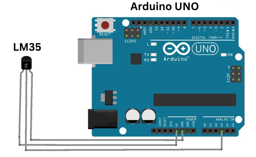
A basic connection is:
| LM35 | Arduino Uno |
|---|---|
| VCC | 5V |
| VOUT | A0 |
| GND | GND |
The Arduino reads the analog voltage on A0 using its ADC. The measured voltage can then be converted into temperature using the LM35’s 10 mV/°C sensitivity.
For example, if the Arduino measures approximately 0.25 V:
Temperature = 0.25 V ÷ 0.010 V/°C = 25°C
This makes the LM35 a useful component for learning how an analog sensor communicates information to a microcontroller.
Arduino Example – Reading Temperature with LM35
In this example, we’re going to read temperature data from the LM35 sensor and display the results in both degrees Celsius (°C) and degrees Fahrenheit (°F) on the Serial Monitor.
// Define the analog pin, the LM35's Vout pin is connected to
#define sensorPin A0

void setup() {
  // Begin serial communication at 9600 baud rate
  Serial.begin(9600);
}

void loop() {
  // Get the voltage reading from the LM35
  int reading = analogRead(sensorPin);

  // Convert that reading into voltage
  // Replace 5.0 with 3.3, if you are using a 3.3V Arduino
  float voltage = reading * (5.0 / 1024.0);

  // Convert the voltage into the temperature in Celsius
  float temperatureC = voltage * 100;

  // Print the temperature in Celsius
  Serial.print("Temperature: ");
  Serial.print(temperatureC);
  Serial.print("°C  |  ");

  // Print the temperature in Fahrenheit
  float temperatureF = (temperatureC * 9.0 / 5.0) + 32.0;
  Serial.print(temperatureF);
  Serial.println("°F");

  delay(1000);  // wait a second between readings
}
Once the sketch is running, try placing your finger on the sensor or blowing gently across it. You should see the temperature rise slightly.
Code Explanation
First, we tell the Arduino which analog pin is connected to the LM35—in this case, analog pin 0.
#define sensorPin A0In the setup() section, we initialize serial communication.
void setup() {
  Serial.begin(9600);
}
In the loop() section, we read the voltage coming from the LM35 sensor using the analogRead() function.
int reading = analogRead(sensorPin);Next, we use the formulas discussed earlier to convert the analog reading into voltage, and then into temperature.
float voltage = reading * (5.0 / 1024.0);

float temperatureC = voltage * 100;
After calculating the temperature in Celsius, we print it to the Serial Monitor.
Serial.print("Temperature: ");
Serial.print(temperatureC);
Serial.print("°C  |  ");
We also want to see the temperature in Fahrenheit, so we convert the Celsius value to Fahrenheit and print that to the Serial Monitor as well.
float temperatureF = (temperatureC * 9.0 / 5.0) + 32.0;
Serial.print(temperatureF);
Serial.println("°F");
Practical Projects using LM35
Download the datasheet: LM35
DS18B20 Temperature Sensors
What Is the DS18B20?
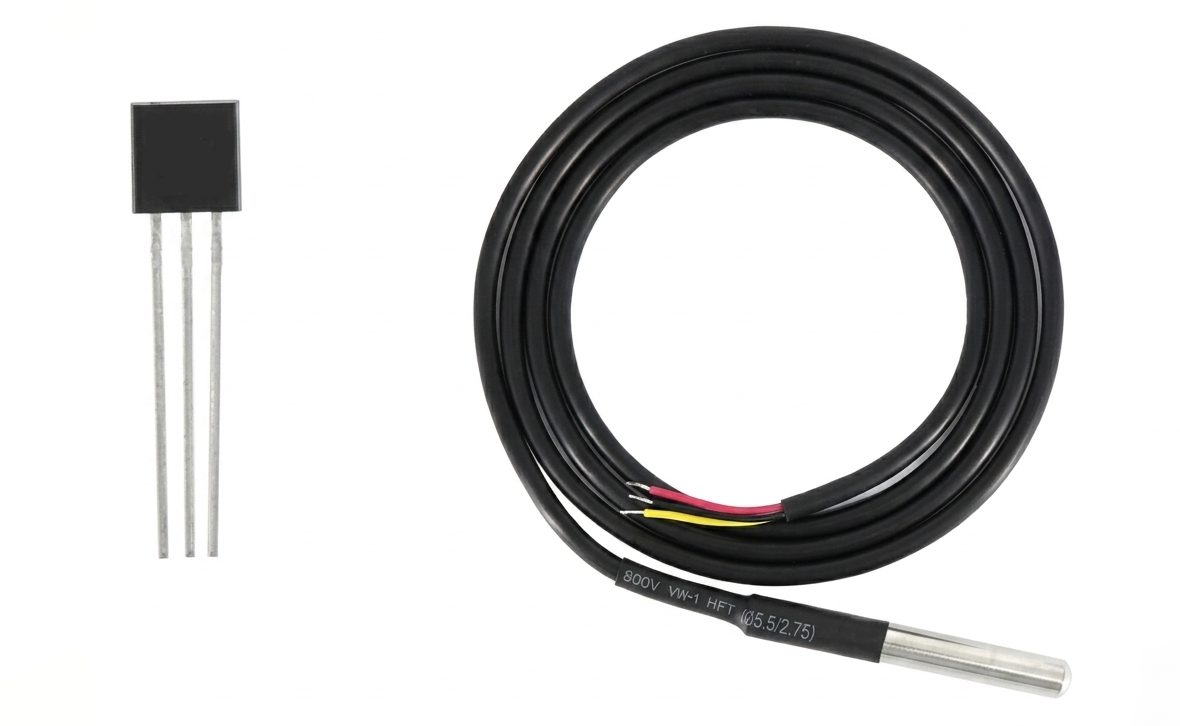
The DS18B20 digital thermometer provides 9-bit to 12-bit temperature measurements and has an alarm function with nonvolatile user-programmable upper and lower trigger points.
The DS18B20 communicates over a 1-Wire® bus that requires only one data line (and ground) for communication with microcontroller. In addition, the DS18B20 can derive power directly from the data line (“parasite power”), eliminating the need for an external power supply.
Each DS18B20 has a unique 64-bit serial code, which allows multiple DS18B20s to function on the same 1-Wire bus. Thus, it is simple to use one microcontroller to control many DS18B20s distributed over a large area.
Applications that can benefit from this feature include HVAC environmental controls, temperature monitoring systems inside buildings, equipment, or machinery.
DS18B20 Package Types
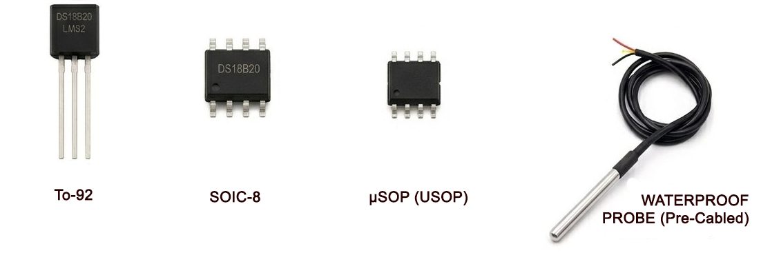
The DS18B20 is available in several package shapes, depending on the specific DS18B20 variant:
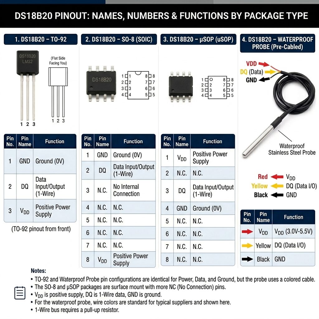
DS18B20 Pinout
Internal Circuitry of the DS18B20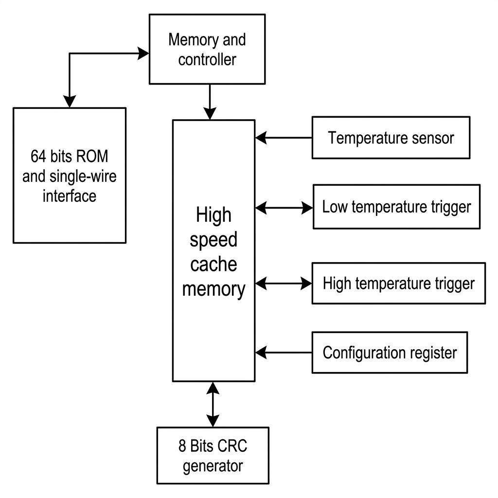
- 64-bit Laser ROM: Stores a unique factory-lasered serial code that acts as a hardware address, allowing multiple sensors to share a
single 1-Wire bus line. - Temperature Sensor: Measures ambient or contact thermal states directly into a digital value configurable from 9 to 12 bits of resolution.
- Alarm Trigger Registers (\(T_{H}\) and \(T_{L}\)): Non-volatile EEPROM components that hold user-defined high and low temperature limits for alarm searches. Scratchpad &
- Configuration Register: A volatile memory space storing the most recent conversion results, configuration data (resolution settings), and internal scratchpad bytes.
- Parasite Power Switch: Internal power-delivery circuitry allowing the chip to steal and store energy directly from the data (DQ) line when VDD is tied to ground, removing the need for an external power rail.
DS18B20 Power Modes
Normal Power:
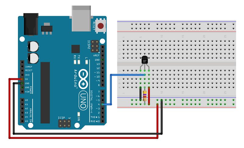
Connect VDD to an external power supply (3.0V to 5.5V), GND to ground, and DQ to your data pin.
Parasitic Power:
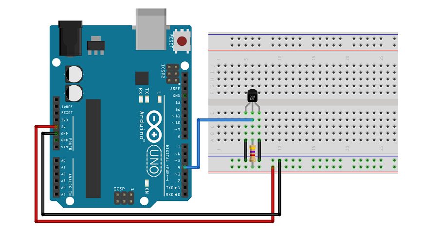
Tie VDD and GND to ground. The chip steals power directly from the data line (DQ) while it stays idle, saving wire traces on your circuit board.
How Does the DS18B20 Work?
The read and write sequence and temperature measurement principle of DS18B20 are the same as DS1820. Only the number of digits of the temperature value obtained varies with the resolution. And the delay time during temperature conversion is reduced from 2s to 750ms.

DS18B20 Temperature Measurement Principle Diagram
The oscillation frequency of the crystal oscillator with low temperature coefficient in the picture is little affected by temperature. It is used to generate a fixed frequency pulse signal and send it to the subtraction counter 1.
The high temperature coefficient crystal oscillator changes its oscillation frequency significantly with temperature changes. At the same time, the generated signal is used as the pulse input of the subtraction counter 2.
The figure also implies a counting gate. When the counting gate is opened, DS18B20 counts the clock pulses generated by the low temperature coefficient oscillator to complete the temperature measurement.
The opening time of the counting gate is determined by the high temperature coefficient oscillator. Before each measurement, first put the base corresponding to -55 ℃ into the subtraction counter 1 and the temperature register respectively. The subtraction counter 1 and the temperature register are preset to a base value corresponding to -55 ℃.
The subtraction counter 1 subtracts the pulse signal generated by the low temperature coefficient crystal oscillator. When the preset value of the subtraction counter 1 is reduced to 0, the value of the temperature register will increase by 1, the preset of the subtraction counter 1 will be reloaded, and the subtraction counter 1 will restart counting the pulse signals generated by the low temperature coefficient crystal oscillator.
This loop until the subtraction counter 2 counts to 0, stop the accumulation of the temperature register value. The value in the temperature register is the measured temperature at this time.
The slope accumulator is used to compensate and correct the nonlinearity in the temperature measurement process, and its output is used to correct the preset value of the subtraction counter.
As long as the counting gate is not closed, repeat the above process until the temperature register value reaches the measured temperature value. This is the temperature measurement principle of DS18B20.
In addition, because the DS18B20 single-wire communication function is completed in time sharing, it has a strict concept of time slots. Therefore, the read and write timing is very important. Various operations of the system to DS18B20 must be carried out according to the agreement.
The operating protocol is:
initialize DS18B20 (send reset pulse) → send ROM function command → send memory operation command → process data. The timing diagram of various operations is the same as that of DS1820.
DS18B20 Specifications
| Parameter | Details |
| Sensor Type | Digital Temperature Sensor |
| Output Type | 1-Wire Digital Output |
| Supply Voltage | +3 to 5.5 V |
| Pull-up Supply Voltage | +3 to 5.5 V |
| Input Logic Low | -0.3 to +0.8 V |
| Input Logic High | +2.2 V |
| Sink Current | 4.0 mA |
| Standby Current | 750 to 1000 nA |
| Active Current | 1 to 1.5 mA |
| DQ Input Current | 5 µA |
| Drift | ±2 °C |
| NV Write Cycle Time | 2 to 10 ms |
| EEPROM Writes | 50k writes |
| EEPROM Data Retention | 10 years |
| Temperature Conversion Time | 93.75 ms |
| Time to Strong Pull-up On | 10 ms |
| Time Slot | 120 µs |
| Recovery Time | 1 µs |
| Write 0 Low Time | 120 µs |
| Write 1 Low Time | 15 µs |
| Read Data Valid | 15 µs |
| Reset Time High | 480 µs |
| Reset Time Low | 480 µs |
| Presence-Detect High | 60 µs |
| Presence-Detect Low | 240 µs |
| Capacitance | 25 pF |
| Available Package Types | To-92, SOIC-8, µSOP (USOP), WATERPROOF PROBE (Pre-Cabled) |
Equivalents & Alternatives of DS18B20
DS18B20 temperature sensor equivalent is DS18S20:
So alternative temperature sensors are
TMP100, Thermocouple, LM75, SHT15, DHT11, TPA81, LM35DZ, D6T, etc.
Advantages of the DS18B20
The advantages of the DS18B20 temperature sensor include the following:
- DS18B20 temperature sensors are small in size.
- These are durable.
- It has a metal covering that protects the sensor from heat & water.
- Multiple sensors can be connected on a similar bus.
- This sensor is easily integrated into a variety of systems.
- It has a user-configurable resolution.
- It provides precise and reliable temperature data for different applications.
Limitations of the DS18B20
Limitations of the DS18B20 temperature sensor include the following:
- This temperature sensor is expensive.
- It takes much time to complete a reading.
- It may not be available with comprehensive packaging, thus you may require using external circuits to work it.
- Data transmission delay occurs.
- Its temperature range is limited ranges from -55°C to 125°C.
Common Applications of the DS18B20
The applications of the DS18B20 temperature sensor include the following:
- The DS18B20 temperature sensor measures the temperature within rigid environments like soil, chemical solutions, mines, and more.
- Users apply it to measure liquid temperature.
- Industries employ it in thermostat control systems as a temperature-measuring device.
- This sensor finds use wherever individuals need to calculate temperature at several points.
- Industrial systems utilize this sensor to measure the temperature of machinery, processes, equipment, and so on.
- Manufacturers use it in consumer products to measure temperature.
- HVAC systems utilize it to measure temperature within buildings, mainly for their controls.
- Thermometers, thermostatic controls, thermally sensitive systems, harsh environments, and Hydro-projects use this temperature sensor.
- Industries use this sensor for temperature measurement, environmental sensing, liquid temperature monitoring, weather stations, and HVAC environmental controls.
Interfacing DS18B20 with Arduino
Let’s learn how to connect the DS18B20 temperature sensor to an Arduino.
The wiring is pretty simple. First, connect the VDD pin of the sensor to the 5V pin on your Arduino. Next, connect the GND (ground) pin of the sensor to any of the Arduino’s GND pins.
For the data connection, connect the sensor’s DQ (data) pin to digital pin 2 on the Arduino. To ensure the data signal remains stable, you’ll need to add a 4.7k ohm pull-up resistor between the DQ pin and the 5V power pin. (Note: the Arduino’s internal pull-up resistors won’t work for this, so you need to use an external one.)
Parts Required
To show you how the sensor works, we’ll build a simple example that reads the temperature from the DS18B20 sensor with the Arduino and displays the values on the Arduino Serial Monitor.
Here’s a list of parts you need to complete this tutorial
- Arduino UNO – read Best Arduino Starter Kits
- DS18B20 temperature sensor (one or multiple sensors) – waterproof version
- 4.7k Ohm resistor
- Breadboard
- Jumper wires
Here’s a quick reference table for the pin connections:
| DS18B20 | Arduino | Notes | |
| VDD | 5V | – | |
| GND | GND | – | |
| DQ | 2 | pulled up by 4.7kΩ |

If you’re using the waterproof DS18B20 probe, the wires are color-coded: Connect the red wire to the Arduino’s 5V pin, the black wire to GND, and the yellow wire to digital pin 2.
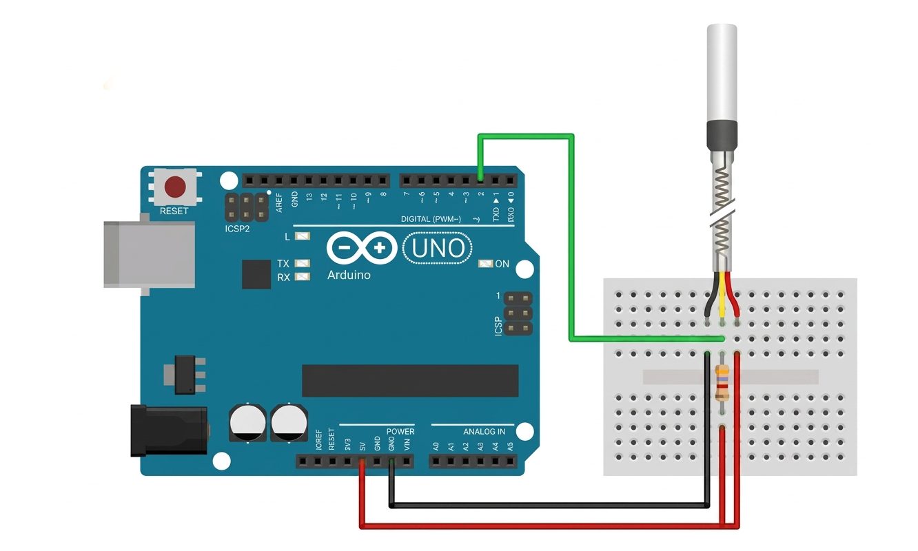
Just like before, don’t forget to add a 4.7k ohm resistor between the yellow wire (data) and the red wire (power) to keep the communication stable.
Example waterproof DS18B20 probe with Arduino
As from the above schematic diagram the VCC and GND of sensor are connected to 5V and GND of Arduino, and DATA pin is connected to pin 7 of Arduino. A 4.7k Ohm pull up resister is connected to data pin from 5V supply for stable data communication.
After connecting all the required components according to the above circuit diagram, we need to upload the code into the Arduino through Arduino IDE.
Setting for the Pull-up Register/Pull-down Register Selection Jumpers When connect DS18B20 with the adapter, please choose to use the Pull-up Register Jumper
Sample Code
/***************************************************************/
 Insturciton:
 Connection:
 1.Plugable Terminal Sensor Adapter & Waterproof DS18B20 Digital Temperature Sensor
                 A   ---->     Blue(DATA SIGNAL)
                 B   ---->     RED   (VIN)
                 C   ---->     Black (GND)

 2.Waterproof DS18B20 Digital Temperature Sensor & Arduino board
              1(A)   ---->     Digital Pin2
              2(B)   ---->     5V/3.3V
              3(C)   ---->     GND

 Setting for the Pull-up Register/Pull-down Register Selection Jumpers
     When connect DS18B20 with the adapter,please choose to use the
     Pull-up Register Jumper
 ***************************************************************/
#include <OneWire.h>

int DS18S20_Pin = 2; //DS18S20 Signal pin on digital 2

//Temperature chip i/o
OneWire ds(DS18S20_Pin);  // on digital pin 2

void setup(void) {
  Serial.begin(9600);
}
Practical projects Using DS18B20
Download the datasheet: DS18B20
Comparisons between LM35 and DS18B20
| Parameter | LM35 | DS18B20 |
|---|---|---|
| Sensor Type | Analog Temperature Sensor | Digital Temperature Sensor |
| Output Type | Analog Voltage | 1-Wire Digital Output |
| Temperature Range | -55 to +150 °C | -55 to +125 °C |
| Accuracy | ±0.5 °C at +25 °C | ±0.5 °C from -10 to +85 °C |
| Resolution | Depends on ADC | 9 to 12 bits |
| Supply Voltage | 4 to 30 V | 3 to 5.5 V |
| Output Voltage | 10 mV/°C | Digital data |
| Communication | Analog | 1-Wire |
| Multiple Sensors | Requires separate ADC channels | Multiple sensors can share one data line |
| Calibration | Factory calibrated | Factory calibrated |
| Conversion Time | Continuous analog output | 93.75 ms to 750 ms, depending on resolution |
| Power Consumption | Approximately 60 µA | Approximately 1 to 1.5 mA active |
| Typical Accuracy | ±0.5 °C at +25 °C | ±0.5 °C from -10 to +85 °C |
| Wiring | Simple | Requires a pull-up resistor |
| Best For | Simple analog temperature measurement | Digital temperature monitoring and multiple sensors |
| Main Advantage | Simple interface and low power consumption | Digital output, configurable resolution, and multi-sensor capability |
Frequently Asked Questions
Why does my LM35 give incorrect temperature readings?
The most common cause of inaccurate LM35 readings is electrical noise on the analog input. To improve accuracy: (1) use a short wire between LM35 and Arduino, (2) add a 100nF decoupling capacitor between the LM35’s VCC pin and GND as close to the chip as possible, (3) average multiple readings (analogRead() called 10 times, sum divided by 10), and (4) switch to the Arduino’s internal 1.1V reference for better ADC resolution at room temperature.
Can I use the DHT11 outdoors?
The DHT11 is not rated for outdoor use. Its temperature range of 0–50°C means it will not work in winter conditions that go below zero, and its plastic housing is not sealed against moisture or rain. For outdoor use, the DS18B20 waterproof probe is a much better choice. If you need humidity outdoors, the SHT31 or BME280 in a waterproof enclosure is the professional approach.
How many DS18B20 sensors can I connect to one Arduino pin?
Theoretically, you can connect up to 127 DS18B20 sensors on a single Arduino pin using the 1-Wire bus (each has a unique 64-bit address). In practice, beyond 10–15 sensors on a long bus you may encounter timing and signal integrity issues. For very long cable runs or many sensors, use a separate 4.7kΩ pull-up per sensor branch and keep wire lengths under 100m. The DallasTemperature library handles all addressing and multi-sensor reading automatically.
What is the difference between DHT11 and DHT22?
The DHT22 (also called AM2302) is the upgraded version of the DHT11. The DHT22 offers better temperature accuracy (±0.5°C vs ±2°C), wider temperature range (-40°C to +80°C vs 0°C to 50°C), better humidity range (0–100% RH vs 20–90% RH), and higher resolution (0.1°C vs 1°C). The DHT22 costs approximately 2–3x more than the DHT11. For serious projects, the DHT22 is worth the price difference. The code for both is identical in the Adafruit DHT library — just change DHT11 to DHT22.
Can I use these sensors with ESP8266 or ESP32 instead of Arduino?
Yes, all three sensors work perfectly with ESP8266 and ESP32 as well. The same libraries (DHT, OneWire, DallasTemperature) are fully compatible. The ESP8266 and ESP32 operate at 3.3V logic — the LM35 should be powered from the 3.3V pin (adjust the millivolt calculation accordingly), while the DHT11 and DS18B20 work fine at both 3.3V and 5V. ESP32 is the preferred choice for IoT temperature logging projects since it has built-in Wi-Fi and Bluetooth.
Conclusion
Choosing between the LM35 and DS18B20 depends on the requirements of your project. The LM35 is a simple, low-cost analog temperature sensor that provides a voltage output proportional to temperature, making it a good choice for basic Arduino and analog measurement projects. The DS18B20, on the other hand, provides digital temperature readings, better wiring flexibility through its 1-Wire interface, and supports multiple sensors on the same data line.
For simple and low-cost temperature measurement, the LM35 is an excellent option. If your project requires digital communication, multiple sensors, longer wiring, or easier integration with microcontrollers, the DS18B20 is generally the better choice.
Ultimately, there is no single sensor that is best for every application. Consider your project’s accuracy requirements, wiring distance, number of sensors, microcontroller compatibility, and software needs before making your choice.
LM35 مقابل DS18B20: كيف تختار مستشعر درجة الحرارة المناسب لمشروعك؟
قائمة المحتويات
- مقدمة عن مستشعرات درجة الحرارة.
- أنواع مستشعرات درجة الحرارة.
- مستشعرات أشباه الموصلات.
- مستشعر درجة الحرارة LM35.
- مستشعر درجة الحرارة DS18B20.
- ما هو DS18B20؟
- أنواع حزم DS18B20.
- ترتيب أطراف DS18B20.
- الدوائر الداخلية في DS18B20.
- أوضاع تشغيل DS18B20.
- كيف يعمل DS18B20؟
- مواصفات DS18B20.
- المعادلات والبدائل لـ DS18B20.
- مزايا DS18B20.
- قيود DS18B20.
- أهم تطبيقات DS18B20.
- توصيل DS18B20 مع Arduino.
- مثال على مسبار DS18B20 المقاوم للماء مع Arduino.
- مشروعات عملية باستخدام DS18B20.
- مقارنة بين LM35 وDS18B20.
- الأسئلة الشائعة.
- الخلاصة.
زمن القراءة حوالي : 20 دقيقة.
مقدمة عن مستشعرات درجة الحرارة
تُعد درجة الحرارة من أكثر الكميات البيئية التي يتم قياسها شيوعًا، وهذا أمر متوقع لأن معظم الأنظمة الفيزيائية والإلكترونية والكيميائية والميكانيكية والبيولوجية تتأثر بدرجة الحرارة. كما أن بعض التفاعلات الكيميائية والعمليات البيولوجية وحتى الدوائر الإلكترونية تعمل بأفضل أداء ضمن نطاقات حرارية محددة. ونظرًا إلى أن درجة الحرارة من أكثر المتغيرات التي يتم قياسها، فقد ظهرت طرق متعددة لاستشعارها وقياسها. ويمكن قياس درجة الحرارة من خلال ملامسة مصدر الحرارة مباشرة، أو عن بُعد باستخدام الطاقة المشعة دون الحاجة إلى ملامسة المصدر. وتتوفر اليوم أنواع عديدة من مستشعرات درجة الحرارة، ومنها المزدوجات الحرارية (Thermocouples)، وكواشف درجة الحرارة المقاومة (RTDs)، والثرمستورات (Thermistors)، والمستشعرات بالأشعة تحت الحمراء، ومستشعرات أشباه الموصلات.
مستشعر درجة الحرارة الدقيق القائم على الدوائر المتكاملة هو جهاز صغير من الحالة الصلبة يقيس درجة الحرارة ويولد جهدًا أو تيارًا يتناسب مع درجة الحرارة المقاسة. وقد صُممت هذه الدوائر المتكاملة أساسًا لقياس درجة الحرارة، إذ تعمل عادةً كمصدر جهد أو مصدر تيار يتغير مع درجة الحرارة، بحيث ترتبط إشارة الخرج مباشرة بدرجة الحرارة المقاسة. ومن أمثلة هذه المستشعرات LM34 وLM35 وغيرها من دوائر استشعار درجة الحرارة. يركز هذا المقال على مستشعر LM35 وطريقة عمله وأهم تطبيقاته، مع مقارنته بمستشعر DS18B20.
أنواع مستشعرات درجة الحرارة
- المزدوج الحراري (Thermocouple).
- كاشف درجة الحرارة المقاوم (RTD).
- الثرمستور (Thermistor).
- مستشعرات أشباه الموصلات.
مستشعرات أشباه الموصلات
يمكن تصنيف مستشعرات درجة الحرارة بصورة أساسية إلى مستشعرات تناظرية وأخرى رقمية. ويختلف أسلوب الحصول على قياس درجة الحرارة بين النوعين، كما تختلف طريقة العمل وإشارة الخرج والاستخدامات المناسبة لكل منهما.
مستشعرات درجة الحرارة التناظرية
- الخرج: تنتج إشارة مستمرة، مثل الجهد أو التيار، تتناسب مع درجة الحرارة المقاسة.
- طريقة العمل: قد تحتاج إلى دوائر إضافية، مثل المضخمات ومحوّلات ADC، لمعالجة الإشارة.
- الدقة: قد تحتاج إلى معايرة دورية للحفاظ على دقة القياس.
- التطبيقات: تُستخدم غالبًا في الأنظمة البسيطة التي لا تحتاج إلى معالجة رقمية.
مستشعرات درجة الحرارة الرقمية
- الخرج: توفر إشارة رقمية يمكن معالجتها مباشرة بواسطة المتحكمات الدقيقة أو الحواسيب.
- طريقة العمل: تدمج عملية تحويل الإشارة ومعالجتها داخل المستشعر، مما يقلل الحاجة إلى مكونات خارجية.
- الدقة: توفر دقة واستقرارًا مرتفعين، مع إمكانات معايرة مدمجة.
- التطبيقات: تناسب الأنظمة المتقدمة التي تحتاج إلى مراقبة دقيقة وموثوقة لدرجة الحرارة، مثل أجهزة إنترنت الأشياء والمعدات الطبية والأنظمة automotive.
ملاحظة مهمة: يشير وصف المستشعر بأنه “تناظري” أو “رقمي” إلى نوع الخرج أو واجهة الاتصال، وليس بالضرورة إلى تقنية الاستشعار الداخلية. فكلا النوعين يمكن أن يعتمد داخليًا على عناصر استشعار قائمة على أشباه الموصلات.
مستشعر درجة الحرارة LM35
ما هو LM35؟
LM35 هو مستشعر تناظري دقيق لدرجة الحرارة، صُمم لقياس درجة الحرارة مباشرة بالدرجات المئوية. ويولد جهد خرج تناظريًا يتغير خطيًا مع درجة الحرارة المقاسة، مما يجعل توصيله مع المتحكمات الدقيقة مثل Arduino ولوحات التطوير الأخرى أمرًا سهلًا.
وعلى عكس مستشعرات درجة الحرارة الرقمية، لا يرسل LM35 بيانات الحرارة باستخدام بروتوكول اتصال. وبدلًا من ذلك، ينتج طرف Vout جهدًا يتناسب مع درجة الحرارة. وتبلغ حساسيته نحو 10 mV/°C، أي أن جهد الخرج يزداد بنحو 10 mV مع كل ارتفاع قدره 1°C في درجة الحرارة.
تجعل هذه العلاقة البسيطة بين الجهد ودرجة الحرارة مستشعر LM35 مناسبًا بشكل خاص للمبتدئين الذين يتعلمون أساسيات المستشعرات التناظرية ودوائر ADC وأنظمة القياس المعتمدة على المتحكمات الدقيقة.
أنواع حزم LM35
يتوفر LM35 بعدة أشكال للحزمة، ويعتمد الشكل المتاح على إصدار LM35 المستخدم.
أشكال حزم مستشعر LM35.
ترتيب أطراف LM35
ترتيب أطراف مستشعر LM35.
الدوائر الداخلية في LM35
على الرغم من أن LM35 يبدو كمكوّن بسيط بثلاثة أطراف يشبه الترانزستور، فإنه يحتوي داخل الحزمة على عدة دوائر وظيفية.
دائرة الاستشعار الحساسة للحرارة
يعتمد جزء الاستشعار على خصائص الوصلات شبه الموصلة التي تتغير مع درجة الحرارة. وتوفر هذه التغيرات المعلومات الكهربائية اللازمة لتحديد درجة الحرارة.
المضخم التفاضلي
تعالج الدائرة الداخلية للمضخم الإشارة الصغيرة المتغيرة مع درجة الحرارة وتساعد على إنتاج خرج المستشعر الخطي.
مرجع الجهد ودوائر المعايرة
تحدد الدوائر الداخلية نقطة التشغيل المناسبة وتساعد في الحفاظ على العلاقة المحددة بين درجة الحرارة والجهد.
مخزن الخرج
توفر مرحلة الخرج الإشارة التناظرية عند طرف Vout، وتسمح للمستشعر بالاتصال بمدخل تناظري في المتحكم الدقيق.
يسمح التصميم الداخلي لـ LM35 بتوفير خرج معاير من المصنع، لذلك لا يحتاج المستخدم عادةً إلى إجراء معايرة منفصلة في التطبيقات العادية.
كيف يعمل LM35؟
يعتمد LM35 على مبدأ عمل الوصلة شبه الموصلة الحساسة للحرارة، حيث يتغير الجهد المرتبط بها مع تغير درجة الحرارة. ومن خلال معالجة هذا التغير بدقة، يمكن إنتاج إشارة تناظرية تتناسب مباشرة مع درجة الحرارة. ويحتوي التصميم الداخلي على ترانزستورين تختلف مساحة الباعث بينهما، ما ينتج فروقًا في كثافة التيار يمكن استخدامها لتوليد جهد مرتبط بدرجة الحرارة.
تحتوي الدائرة أيضًا على مضخم يقارن الإشارات الناتجة عن الترانزستورين، ثم يعالج الفرق بينهما للحصول على خرج يتناسب مع درجة الحرارة.
مع كل ارتفاع قدره 1°C، يرتفع جهد الخرج عند طرف Vout بنحو 10mV، ولذلك تكون العلاقة بين درجة الحرارة والجهد بسيطة:
جهد الخرج = درجة الحرارة (°C) × 10mV
مثال:
- عند 0°C → الخرج = 0mV.
- عند 25°C → الخرج = 250mV.
- عند 100°C → الخرج = 1000mV (1V).
وبما أن الخرج عبارة عن جهد تناظري، يستطيع متحكم مثل Arduino قراءته من خلال مدخل ADC ثم تحويله إلى درجة حرارة باستخدام معادلة بسيطة.
مواصفات LM35
| المعلمة | التفاصيل |
|---|---|
| نوع المستشعر | مستشعر تناظري لدرجة الحرارة. |
| نوع الخرج | جهد تناظري. |
| جهد التغذية | 4 V إلى 30 V. |
| تيار التغذية | 60 µA نموذجيًا. |
| تيار السكون | 56 µA نموذجيًا. |
| نطاق درجة الحرارة | −55°C إلى +150°C. |
| الحساسية | 10 mV/°C. |
| الدقة | ±0.5°C عند 25°C. |
| نطاق جهد الخرج | تقريبًا من −550mV إلى +1500mV. |
| تيار الحمل | 1mA كحد أقصى. |
| زمن الاستجابة | نحو ثانية واحدة في الهواء الساكن. |
| درجة حرارة التخزين | −60°C إلى +155°C. |
| أنواع الحزم المتاحة | TO-92 / TO-220 / TO-CAN / SOIC-8. |
ملاحظة: تعتمد هذه القيم على المعلومات التقنية الواردة في المصدر المستخدم، وللتصاميم الإنتاجية يجب الرجوع إلى ورقة البيانات الخاصة برقم الجزء المحدد باعتبارها المرجع النهائي.
المعادلات والبدائل لـ LM35
المستشعرات المكافئة لـ LM35:
LM34، DS1620، DS18B20، LM94022، وغيرها.
مستشعرات بديلة:
DHT11، LM35، DHT22، DS18B20، BMP180، BME280، وغيرها.
مزايا LM35
- خرج خطي: يتغير جهد الخرج بصورة متوقعة مع تغير درجة الحرارة.
- واجهة بسيطة: يمكن توصيله مباشرة بمدخل تناظري.
- استهلاك منخفض للتيار: يبلغ استهلاك التيار النموذجي نحو 60µA.
- نطاق قياس واسع: مناسب لدرجات حرارة من −55°C إلى +150°C.
- سهولة تحويل درجة الحرارة: تجعل حساسية 10mV/°C عملية الحساب مباشرة.
- تسخين ذاتي منخفض: يساعد استهلاك الطاقة المنخفض على تقليل تأثير المستشعر في درجة الحرارة المقاسة.
- حزمة مدمجة: يتوفر بعدة خيارات صغيرة للحزمة.
قيود LM35
- LM35 مستشعر بسيط وعملي، لكن خرجه التناظري يفرض بعض الاعتبارات أثناء التصميم.
- نظرًا إلى أن معلومات درجة الحرارة تنتقل على شكل جهد، فقد تتأثر القراءة بدقة ADC في المتحكم، وجهد المرجع، والضوضاء الكهربائية، وطول الأسلاك. كما قد تظهر محدودية في الدقة والاستجابة وتأثر أكبر بالتشويش مقارنة ببعض المستشعرات الرقمية.
- في التطبيقات التي تحتاج إلى اتصال رقمي، أو وظائف تشخيص متقدمة، أو عدة مستشعرات على خط بيانات واحد، قد يكون مستشعر رقمي مثل DS18B20 أكثر ملاءمة.
أهم تطبيقات LM35
يمكن استخدام LM35 في العديد من التطبيقات التي تتطلب قياس درجة الحرارة أو مراقبتها.
- مراقبة درجة حرارة البيئة.
- مشروعات Arduino والمتحكمات الدقيقة.
- مراقبة أنظمة HVAC والتحكم فيها.
- مراقبة العمليات الصناعية.
- قياس درجة الحرارة في المختبرات.
- مراقبة درجة حرارة البطاريات.
- مراقبة الحرارة في المعدات الإلكترونية.
- مراقبة درجة الحرارة في تطبيقات السيارات.
- مراقبة درجة الحرارة في عمليات تصنيع الأغذية.
- الأنظمة التي تعتمد على التحكم في درجة الحرارة.
- دوائر الحماية الحرارية والإيقاف عند ارتفاع الحرارة.
توصيل LM35 مع Arduino
يمكن توصيل LM35 بسهولة مع Arduino Uno لأن Arduino يوفر مداخل تناظرية قادرة على قياس جهد خرج المستشعر.
التوصيل الأساسي:
| طرف LM35 | Arduino Uno |
|---|---|
| VCC | 5V |
| VOUT | A0 |
| GND | GND |
يقرأ Arduino الجهد التناظري على الطرف A0 باستخدام ADC، ثم يمكن تحويل الجهد المقاس إلى درجة حرارة اعتمادًا على حساسية LM35 البالغة 10mV/°C.
على سبيل المثال، إذا قاس Arduino جهدًا يقارب 0.25V:
درجة الحرارة = 0.25V ÷ 0.010V/°C = 25°C
وهذا يجعل LM35 مكونًا مفيدًا لتعلم كيفية نقل المستشعر التناظري للمعلومات إلى المتحكم الدقيق.
مثال Arduino – قراءة درجة الحرارة باستخدام LM35
في هذا المثال سنقرأ بيانات درجة الحرارة من مستشعر LM35 ونعرض النتائج بالدرجات المئوية (°C) والفهرنهايت (°F) على Serial Monitor.
#define sensorPin A0

void setup() {
  Serial.begin(9600);
}

void loop() {
  int reading = analogRead(sensorPin);
  float voltage = reading * (5.0 / 1024.0);
  float temperatureC = voltage * 100;

  Serial.print("Temperature: ");
  Serial.print(temperatureC);
  Serial.print("°C  |  ");

  float temperatureF = (temperatureC * 9.0 / 5.0) + 32.0;
  Serial.print(temperatureF);
  Serial.println("°F");

  delay(1000);
}
بعد تشغيل البرنامج، جرّب لمس المستشعر بإصبعك أو النفخ عليه برفق. من المفترض أن تلاحظ ارتفاعًا طفيفًا في درجة الحرارة المقروءة.
شرح الكود
أولًا نحدد طرف Arduino التناظري المتصل بمخرج LM35، وهو في هذه الحالة الطرف A0.
#define sensorPin A0في الدالة setup() نبدأ الاتصال التسلسلي.
void setup() {
  Serial.begin(9600);
}
في الدالة loop() نقرأ الجهد القادم من مستشعر LM35 باستخدام الدالة analogRead().
int reading = analogRead(sensorPin);بعد ذلك نستخدم المعادلات لتحويل القراءة التناظرية إلى جهد، ثم تحويل الجهد إلى درجة حرارة.
float voltage = reading * (5.0 / 1024.0);

float temperatureC = voltage * 100;
بعد حساب درجة الحرارة بالمئوية، نعرضها على Serial Monitor.
Serial.print("Temperature: ");
Serial.print(temperatureC);
Serial.print("°C  |  ");
كما نحول قيمة درجة الحرارة من المئوية إلى الفهرنهايت ونعرضها على Serial Monitor.
float temperatureF = (temperatureC * 9.0 / 5.0) + 32.0;
Serial.print(temperatureF);
Serial.println("°F");
مشروعات عملية باستخدام LM35
تحميل ورقة البيانات: LM35
مستشعر درجة الحرارة DS18B20
ما هو DS18B20؟
يوفر مستشعر الحرارة الرقمي DS18B20 قياسات لدرجة الحرارة بدقة قابلة للضبط من 9 إلى 12 بت، كما يحتوي على وظيفة إنذار مع حدود علوية وسفلية يمكن للمستخدم برمجتها وتخزينها في ذاكرة غير متطايرة.
يتواصل DS18B20 عبر ناقل 1-Wire يحتاج إلى خط بيانات واحد فقط بالإضافة إلى الأرضي للتواصل مع المتحكم الدقيق. كما يستطيع المستشعر الحصول على الطاقة مباشرة من خط البيانات فيما يعرف باسم التغذية الطفيلية (Parasite Power)، مما يلغي الحاجة إلى مصدر طاقة خارجي في هذا الوضع.
يمتلك كل DS18B20 رمزًا تسلسليًا فريدًا من 64 بت، مما يسمح بتشغيل عدة مستشعرات DS18B20 على ناقل 1-Wire نفسه. وبذلك يمكن لمتحكم دقيق واحد إدارة عدد من المستشعرات الموزعة على مساحة كبيرة.
ومن التطبيقات المناسبة لهذه الميزة أنظمة التحكم البيئي في HVAC وأنظمة مراقبة درجات الحرارة داخل المباني والمعدات والآلات.
أنواع حزم DS18B20
يتوفر DS18B20 بعدة أشكال للحزمة، ويعتمد الشكل على إصدار المستشعر المستخدم.
أشكال حزم مستشعر DS18B20
ترتيب أطراف DS18B20
ترتيب أطراف مستشعر DS18B20
الدوائر الداخلية في DS18B20
- ذاكرة ROM بحجم 64 بت: تخزن رمزًا تسلسليًا فريدًا مبرمجًا في المصنع ويعمل كعنوان للمستشعر، مما يسمح بتوصيل عدة مستشعرات على خط 1-Wire واحد.
- مستشعر درجة الحرارة: يقيس درجة الحرارة ويحولها إلى قيمة رقمية يمكن ضبط دقة تمثيلها من 9 إلى 12 بت.
- مسجلات حدود الإنذار (TH وTL): تحفظ حدود درجات الحرارة العليا والسفلى التي يحددها المستخدم لاستخدامها في وظائف الإنذار.
- مسجل الإعداد والذاكرة المؤقتة: يحتفظ بنتائج التحويل الأخيرة وإعدادات المستشعر، بما في ذلك دقة القياس، والبيانات المؤقتة.
- مفتاح التغذية الطفيلية: يتيح للمستشعر الحصول على الطاقة مباشرة من خط البيانات DQ عند استخدام وضع التغذية الطفيلية.
أوضاع تشغيل DS18B20
التغذية العادية
يتم توصيل VDD بمصدر طاقة خارجي من 3.0V إلى 5.5V، وتوصيل GND بالأرضي، وDQ بطرف البيانات في المتحكم.
التغذية الطفيلية
في هذا الوضع يتم توصيل VDD وGND وفق دائرة التغذية الطفيلية، ويستمد المستشعر الطاقة مباشرة من خط البيانات DQ أثناء فترات الخمول، مما يقلل عدد خطوط التغذية المطلوبة.
كيف يعمل DS18B20؟
يعتمد مبدأ قياس درجة الحرارة في DS18B20 على آلية العد الداخلية المرتبطة بتغير تردد المذبذبات مع درجة الحرارة. ويختلف عدد الخانات في قيمة درجة الحرارة الناتجة وفق إعداد الدقة. كما يتراوح زمن تحويل درجة الحرارة بحسب إعداد الدقة، ويمكن أن يصل إلى 750ms عند أعلى دقة.
مخطط مبدأ قياس درجة الحرارة في DS18B20
يكون تردد المذبذب ذي المعامل الحراري المنخفض أقل تأثرًا بتغير درجة الحرارة، ويُستخدم لتوليد نبضات بتردد مرجعي. أما المذبذب ذي المعامل الحراري المرتفع فتتغير تردداته بصورة أكبر مع تغير درجة الحرارة، وتُستخدم إشارته للتحكم في عملية القياس.
عند فتح بوابة العد، يقوم DS18B20 بعد نبضات الساعة الناتجة عن المذبذب ذي المعامل الحراري المنخفض لإتمام عملية قياس درجة الحرارة.
يتم تحديد زمن فتح بوابة العد بواسطة المذبذب ذي المعامل الحراري المرتفع، وتبدأ عملية القياس بقيم مرجعية مرتبطة بالحد الأدنى لنطاق القياس.
تعمل عدادات القياس بصورة متكررة حتى الوصول إلى القيمة التي تمثل درجة الحرارة المقاسة، ثم تُحفظ النتيجة في سجل درجة الحرارة.
يُستخدم مجمع الميل لتعويض اللاخطية في عملية القياس وتصحيح قيم العد الداخلية، مما يساعد على تحسين دقة النتيجة.
وبمجرد اكتمال عملية العد والوصول إلى القيمة المقاسة، تصبح القيمة الموجودة في سجل درجة الحرارة هي درجة الحرارة الناتجة عن القياس.
وبسبب اعتماد اتصال DS18B20 على تقسيم الزمن، فإن بروتوكول 1-Wire يعتمد على مفهوم دقيق لفترات التوقيت. لذلك يجب الالتزام بتوقيتات القراءة والكتابة عند تنفيذ عمليات الاتصال مع المستشعر.
تسلسل التشغيل:
تهيئة DS18B20 (إرسال نبضة إعادة الضبط) ← إرسال أمر وظيفة ROM ← إرسال أمر تشغيل الذاكرة ← معالجة البيانات.
مواصفات DS18B20
| المعلمة | التفاصيل |
|---|---|
| نوع المستشعر | مستشعر رقمي لدرجة الحرارة. |
| نوع الخرج | خرج رقمي عبر 1-Wire. |
| جهد التغذية | +3 إلى 5.5V. |
| جهد تغذية المقاومة السحبية | +3 إلى 5.5V. |
| منطق الدخل المنخفض | −0.3 إلى +0.8V. |
| منطق الدخل المرتفع | +2.2V. |
| تيار السحب | 4.0mA. |
| تيار الاستعداد | 750 إلى 1000nA. |
| التيار أثناء التشغيل | 1 إلى 1.5mA. |
| تيار دخل DQ | 5µA. |
| الانجراف | ±2°C. |
| زمن دورة الكتابة غير المتطايرة | 2 إلى 10ms. |
| عدد كتابات EEPROM | 50k عملية كتابة. |
| الاحتفاظ ببيانات EEPROM | 10 سنوات. |
| زمن تحويل درجة الحرارة | 93.75ms. |
| زمن تفعيل السحب القوي | 10ms. |
| الفترة الزمنية | 120µs. |
| زمن الاستعادة | 1µs. |
| زمن المستوى المنخفض لكتابة 0 | 120µs. |
| زمن المستوى المنخفض لكتابة 1 | 15µs. |
| صلاحية قراءة البيانات | 15µs. |
| زمن إعادة الضبط – المستوى المرتفع | 480µs. |
| زمن إعادة الضبط – المستوى المنخفض | 480µs. |
| اكتشاف وجود المستشعر – المستوى المرتفع | 60µs. |
| اكتشاف وجود المستشعر – المستوى المنخفض | 240µs. |
| السعة | 25pF. |
| أنواع الحزم المتاحة | TO-92، SOIC-8، µSOP (USOP)، مسبار مقاوم للماء مزود مسبقًا بالكابل. |
المعادلات والبدائل لـ DS18B20
المستشعر المكافئ لـ DS18B20 هو DS18S20.
ومن البدائل الأخرى:
TMP100، Thermocouple، LM75، SHT15، DHT11، TPA81، LM35DZ، D6T، وغيرها.
مزايا DS18B20
- حجم صغير.
- متانة جيدة.
- تتوفر بعض إصداراته بغطاء معدني يحمي المستشعر من الحرارة والماء.
- يمكن توصيل عدة مستشعرات على ناقل بيانات واحد.
- يسهل دمجه في مجموعة متنوعة من الأنظمة.
- يوفر دقة قياس قابلة للضبط.
- يوفر بيانات درجة حرارة دقيقة وموثوقة لمجموعة متنوعة من التطبيقات.
قيود DS18B20
- قد تكون تكلفته أعلى من بعض مستشعرات الحرارة البسيطة.
- يحتاج إلى وقت لإتمام عملية تحويل وقراءة درجة الحرارة.
- قد يتطلب بعض التطبيقات استخدام دائرة أو ملحقات إضافية حسب شكل الحزمة وطريقة التركيب.
- توجد فترة زمنية مرتبطة بتحويل البيانات والاتصال الرقمي.
- نطاق درجة الحرارة في المستشعر محدود من −55°C إلى +125°C.
أهم تطبيقات DS18B20
- قياس درجة الحرارة في البيئات مثل التربة والمحاليل الكيميائية والمناجم وغيرها.
- قياس درجة حرارة السوائل.
- أنظمة التحكم في منظمات الحرارة (Thermostats).
- التطبيقات التي تتطلب قياس درجة الحرارة في عدة نقاط.
- قياس درجة حرارة الآلات والعمليات والمعدات في الأنظمة الصناعية.
- قياس درجة الحرارة في المنتجات الاستهلاكية.
- أنظمة HVAC لمراقبة درجة الحرارة داخل المباني والتحكم فيها.
- موازين الحرارة وأنظمة التحكم الحراري والأنظمة الحساسة للحرارة والبيئات القاسية.
- قياس درجة الحرارة البيئية، ومراقبة السوائل، ومحطات الطقس، وأنظمة التحكم البيئي في HVAC.
توصيل DS18B20 مع Arduino
يمكن توصيل مستشعر درجة الحرارة DS18B20 بسهولة مع Arduino.
ابدأ بتوصيل طرف VDD بالطرف 5V في Arduino، ثم صِل طرف GND بأي طرف أرضي في Arduino.
بالنسبة إلى البيانات، صِل طرف DQ بالطرف الرقمي 2 في Arduino. وللحفاظ على استقرار إشارة البيانات، يجب إضافة مقاومة سحب لأعلى بقيمة 4.7kΩ بين DQ وخط 5V. ولا تكفي مقاومات السحب الداخلية في Arduino لهذا الغرض، لذلك يوصى باستخدام مقاومة خارجية.
المكونات المطلوبة
- Arduino UNO.
- مستشعر درجة الحرارة DS18B20، ويمكن استخدام مستشعر واحد أو عدة مستشعرات، بما في ذلك الإصدار المقاوم للماء.
- مقاومة 4.7kΩ.
- لوحة تجارب Breadboard.
- أسلاك توصيل Jumper.
جدول سريع لتوصيلات الأطراف:
| DS18B20 | Arduino | ملاحظات |
|---|---|---|
| VDD | 5V | — |
| GND | GND | — |
| DQ | 2 | مع مقاومة سحب لأعلى 4.7kΩ. |
إذا كنت تستخدم مسبار DS18B20 المقاوم للماء، فعادةً تكون الأسلاك مميزة بالألوان: صِل السلك الأحمر بالطرف 5V في Arduino، والأسود بالطرف GND، والأصفر بالطرف الرقمي 2.
ولا تنسَ إضافة مقاومة 4.7kΩ بين سلك البيانات الأصفر وسلك التغذية الأحمر للمساعدة في استقرار الاتصال.
مثال على مسبار DS18B20 المقاوم للماء مع Arduino
وفقًا للمخطط، يتم توصيل VCC وGND للمستشعر مع 5V وGND في Arduino، بينما يتم توصيل طرف DATA بالطرف الرقمي المحدد في Arduino. كما توصل مقاومة سحب لأعلى بقيمة 4.7kΩ بين خط البيانات ومصدر 5V لضمان استقرار الاتصال.
بعد توصيل جميع المكونات المطلوبة وفق مخطط الدائرة، يتم رفع البرنامج إلى Arduino باستخدام Arduino IDE.
عند استخدام محول DS18B20، اختر إعداد وصلة مقاومة السحب لأعلى (Pull-up Jumper) وفق إعدادات المحول.
الكود التجريبي
#include <OneWire.h>

int DS18S20_Pin = 2; // طرف إشارة DS18S20 متصل بالطرف الرقمي 2

OneWire ds(DS18S20_Pin); // على الطرف الرقمي 2

void setup(void) {
  Serial.begin(9600);
}
مشروعات عملية باستخدام DS18B20
تحميل ورقة البيانات: DS18B20
مقارنة بين LM35 وDS18B20
| المعلمة | LM35 | DS18B20 |
|---|---|---|
| نوع المستشعر | مستشعر تناظري لدرجة الحرارة | مستشعر رقمي لدرجة الحرارة |
| نوع الخرج | جهد تناظري | خرج رقمي 1-Wire |
| نطاق درجة الحرارة | −55 إلى +150°C | −55 إلى +125°C |
| الدقة | ±0.5°C عند +25°C | ±0.5°C من −10 إلى +85°C |
| الدقة الرقمية | تعتمد على ADC | 9 إلى 12 بت |
| جهد التغذية | 4 إلى 30V | 3 إلى 5.5V |
| خرج الجهد | 10mV/°C | بيانات رقمية |
| الاتصال | تناظري | 1-Wire |
| توصيل عدة مستشعرات | يتطلب مداخل ADC منفصلة | يمكن لعدة مستشعرات مشاركة خط بيانات واحد |
| المعايرة | معاير من المصنع | معاير من المصنع |
| زمن التحويل | خرج تناظري مستمر | 93.75ms إلى 750ms بحسب الدقة |
| استهلاك الطاقة | نحو 60µA | نحو 1 إلى 1.5mA أثناء التشغيل |
| الاستخدام الأفضل | قياس درجة الحرارة التناظري البسيط | المراقبة الرقمية وقياس الحرارة باستخدام عدة مستشعرات |
| الميزة الرئيسية | واجهة بسيطة واستهلاك منخفض للطاقة | خرج رقمي، ودقة قابلة للضبط، وإمكانية توصيل عدة مستشعرات |
الأسئلة الشائعة
لماذا يعطي LM35 قراءات غير صحيحة لدرجة الحرارة؟
من أكثر أسباب عدم دقة قراءة LM35 شيوعًا وجود ضوضاء كهربائية على المدخل التناظري. لتحسين الدقة، يمكن استخدام سلك قصير بين LM35 وArduino، وإضافة مكثف إزالة تشويش بقيمة 100nF بين VCC وGND بالقرب من المستشعر قدر الإمكان، وحساب متوسط عدة قراءات، مثل إجراء analogRead() عشر مرات ثم قسمة مجموع القراءات على 10. كما يمكن استخدام مرجع Arduino الداخلي 1.1V لتحسين دقة ADC عند درجات حرارة الغرفة.
هل يمكن استخدام DHT11 في الخارج؟
مستشعر DHT11 غير مخصص للاستخدام الخارجي. فنطاق درجة حرارته من 0 إلى 50°C، وبالتالي قد لا يعمل في الظروف التي تنخفض فيها الحرارة إلى ما دون الصفر، كما أن غلافه البلاستيكي لا يوفر حماية محكمة من الرطوبة أو المطر. للاستخدام الخارجي، يكون مسبار DS18B20 المقاوم للماء خيارًا أفضل. وإذا كان المشروع يحتاج إلى قياس الرطوبة أيضًا، فيمكن استخدام SHT31 أو BME280 داخل حاوية مقاومة للماء.
كم عدد مستشعرات DS18B20 التي يمكن توصيلها بطرف Arduino واحد؟
من الناحية النظرية، يمكن توصيل ما يصل إلى 127 مستشعر DS18B20 بطرف Arduino واحد باستخدام ناقل 1-Wire، لأن لكل مستشعر عنوانًا فريدًا من 64 بت. لكن عمليًا، قد تظهر مشكلات في التوقيت وسلامة الإشارة عند استخدام أكثر من 10 إلى 15 مستشعرًا على ناقل طويل. وعند استخدام كابلات طويلة أو عدد كبير من المستشعرات، يجب الانتباه إلى تصميم خط البيانات ومقاومات السحب لأعلى وطول الأسلاك. ويمكن لمكتبة DallasTemperature إدارة عناوين المستشعرات وقراءة عدة مستشعرات.
ما الفرق بين DHT11 وDHT22؟
يُعد DHT22، المعروف أيضًا باسم AM2302، إصدارًا مطورًا من DHT11. ويوفر DHT22 دقة أفضل في قياس درجة الحرارة (±0.5°C مقابل ±2°C)، ونطاق درجة حرارة أوسع (−40°C إلى +80°C مقابل 0°C إلى 50°C)، ونطاق رطوبة أكبر (0–100% RH مقابل 20–90% RH)، ودقة أعلى في القياس (0.1°C مقابل 1°C). وتبلغ تكلفته عادةً نحو ضعفين إلى ثلاثة أضعاف تكلفة DHT11. وللتطبيقات الأكثر جدية، قد يكون فرق السعر مبررًا. وتتشابه طريقة استخدام المستشعرين مع مكتبة Adafruit DHT، مع تغيير نوع المستشعر في الكود.
هل يمكن استخدام هذه المستشعرات مع ESP8266 أو ESP32 بدلًا من Arduino؟
نعم، يمكن استخدام المستشعرات المذكورة مع ESP8266 وESP32 أيضًا. وتتوفر مكتبات مثل DHT وOneWire وDallasTemperature للتعامل مع هذه المستشعرات. تعمل ESP8266 وESP32 بمنطق 3.3V، لذلك يجب الانتباه إلى طريقة تغذية LM35 وحساب الجهد المقروء بما يتناسب مع مرجع ADC المستخدم، بينما يمكن تشغيل DS18B20 ضمن نطاق جهد التغذية المناسب له. ويُعد ESP32 خيارًا مناسبًا لمشروعات تسجيل درجة الحرارة عبر إنترنت الأشياء بفضل وجود Wi-Fi وBluetooth مدمجين.
الخلاصة
يعتمد الاختيار بين LM35 وDS18B20 على متطلبات المشروع. يُعد LM35 مستشعرًا تناظريًا بسيطًا ومنخفض التكلفة، حيث يوفر جهد خرج يتناسب مع درجة الحرارة، مما يجعله مناسبًا لمشروعات Arduino الأساسية وتطبيقات القياس التناظري. أما DS18B20 فيوفر قراءة رقمية لدرجة الحرارة، ومرونة أكبر في التوصيل بفضل واجهة 1-Wire، كما يسمح بتوصيل عدة مستشعرات على خط بيانات واحد.
• إذا كان المطلوب قياس درجة الحرارة بطريقة بسيطة ومنخفضة التكلفة، فإن LM35 خيار ممتاز.
• إذا كان المشروع يحتاج إلى اتصال رقمي، أو عدة مستشعرات، أو أسلاك أطول، أو تكامل أسهل مع المتحكمات الدقيقة، فإن DS18B20 يكون غالبًا الخيار الأنسب.
• لا يوجد مستشعر واحد هو الأفضل لجميع التطبيقات. لذلك يجب مراعاة دقة القياس المطلوبة، ومسافة التوصيل، وعدد المستشعرات، وتوافق المستشعر مع المتحكم الدقيق، ومتطلبات البرمجة قبل اتخاذ القرار.
وبالتالي، يعتمد اختيار مستشعر درجة الحرارة المناسب ليس فقط على دقة القياس، بل أيضًا على طريقة الاتصال، وطبيعة المشروع، وعدد المستشعرات المطلوبة، وسهولة دمجه مع النظام الإلكتروني.
Related Posts

The Relays
The Relays Contents List Introduction. What Is a Relay? How Does a Relay Work?

Everything You Need to Know About EEPROM
Contents List Introduction to EEPROM. What Is EEPROM? How Does EEPROM Work? Main Types

TM1990A iButton Access: Smart Reader & Security Key
TM1990A iButton Access: Smart Reader & Security Key Contents List Introduction What Is the

The Importance of Crystal Oscillators in Electronics
The Importance of Crystal Oscillators in Electronics Contents List Introduction What Is a Crystal

Transistors: Small Components … Big Possibilities
Transistors: Small Components … Big Possibilities Contents List Introduction to Transistors What Is a
Leave a comment
You must be logged in to post a comment.