



In this guide, we’ll break down everything you need to know about the TP4056: from its core specs and pinout to real-world wiring, project examples, and even alternatives. By the end, you’ll be confident using this module for your next build.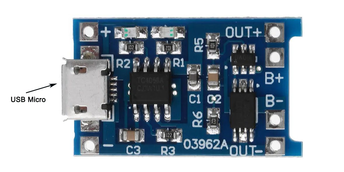
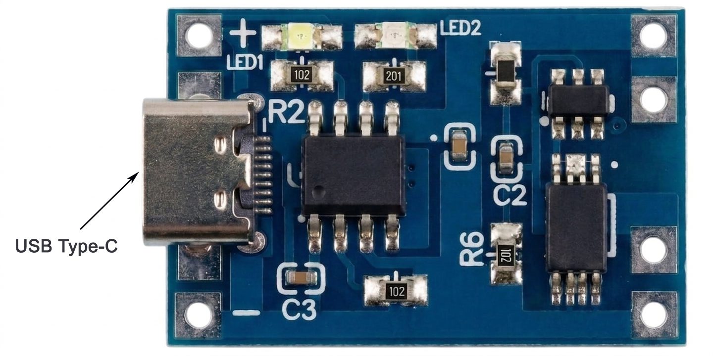
TP4056 Charging Module
What is a TP4056 Charging Module?
The TP4056 module is a compact, ready-to-use board built around the TP4056 IC—a highly integrated linear charger IC designed specifically for single-cell Li-ion/LiPo batteries (3.7V typical). Unlike bulky, custom charging circuits, the TP4056 module comes pre-soldered with all necessary components (resistors, capacitors, LEDs) to handle charging safely—no advanced electronics knowledge required.
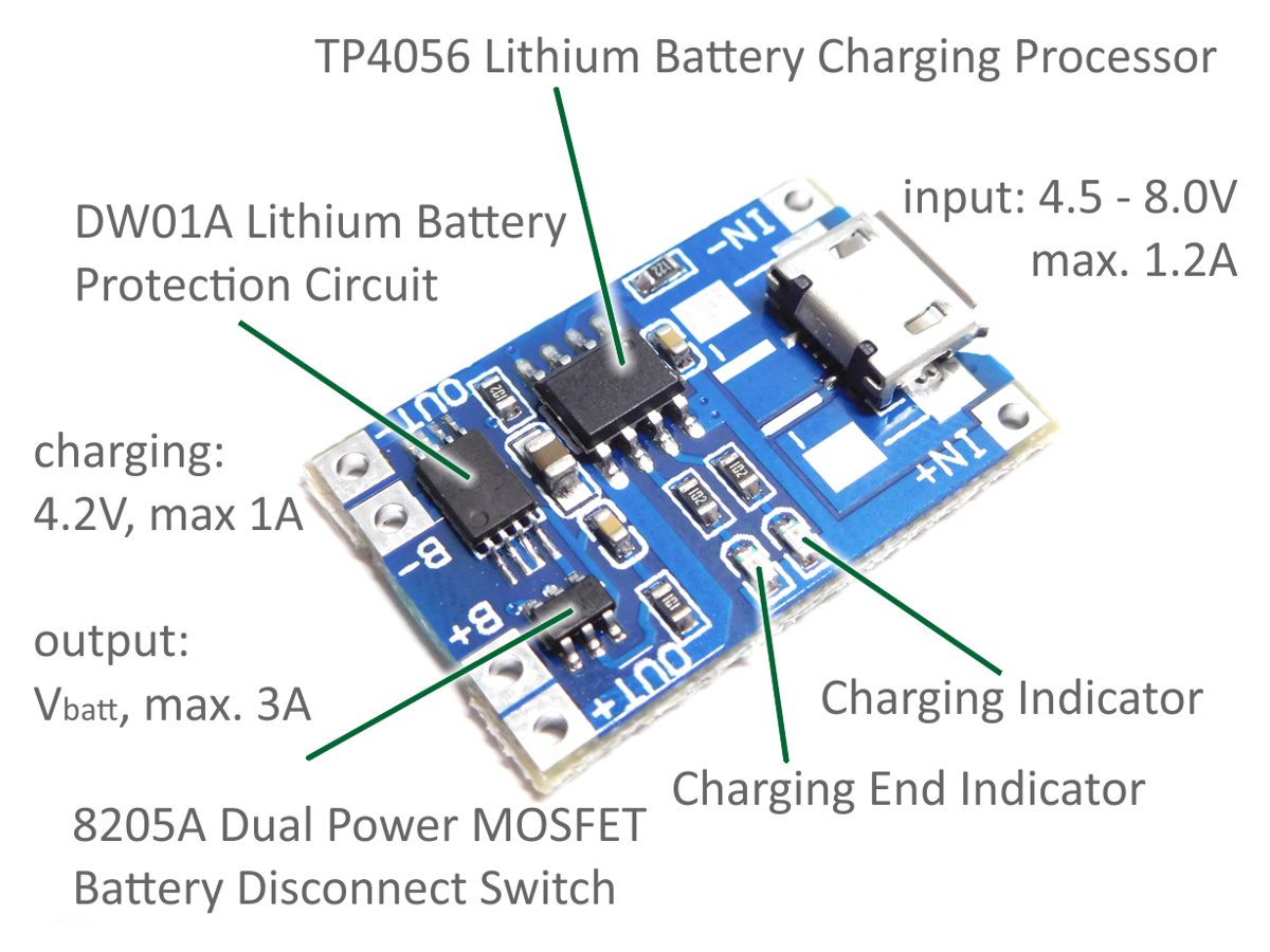
Key Features that make it popular
- Supports single-cell 3.7V Li-ion and LiPo batteries.
- Provides up to 1A charging current.
- Includes constant-current and constant-voltage charging.
- Features automatic charging termination when the battery is fully charged.
- Provides overcharge protection for safer battery charging.
- Compact module design saves space in electronic projects.
- Suitable for DIY electronics, portable devices, and battery-powered projects.
- Easy to integrate into Arduino, ESP32, and other microcontroller projects.
- Low-cost charging solution for single-cell Li-ion and LiPo batteries.
- Built-in charging status LEDs indicate charging and fully charged conditions.
- Adjustable charging current by changing the TP4056 current-setting resistor.
- Supports USB and DC power inputs for flexible charging applications.
- Optional battery protection can be added using a protection circuit such as the DW01A IC.
Introduction to the Characteristics and Functions of TP4056 Chip
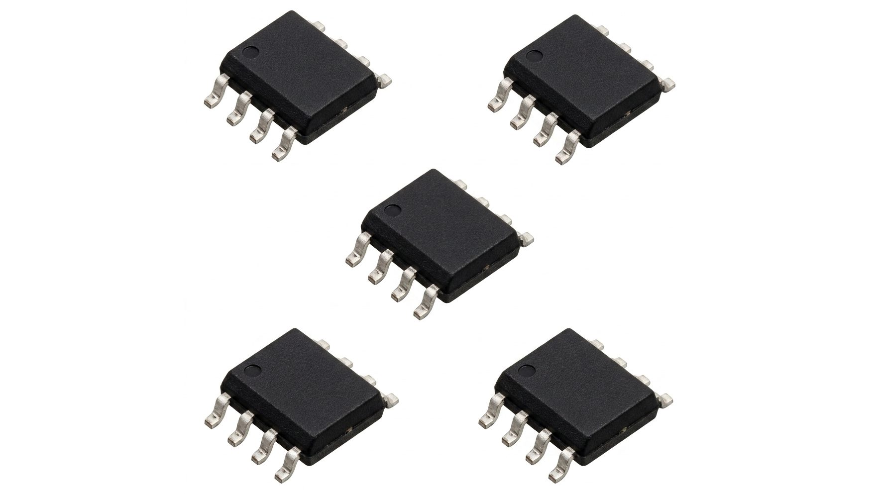
TP4056 is a dedicated chip widely used in lithium – ion battery charging management. It has multiple protection functions and is suitable for portable devices powered by USB ports or adapters. This chip integrates charging current regulation, charging status indication, and comprehensive battery protection mechanisms.
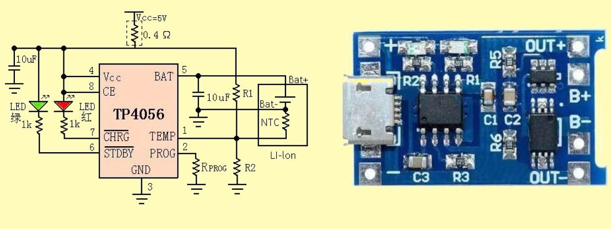
The short – circuit protection function of the chip can respond quickly when a short – circuit occurs at the output end, limiting the output current and avoiding possible damage. The over – temperature protection function monitors the ambient temperature in real – time through a temperature sensor to prevent safety problems caused by overheating.
The above chapter introduces the basic characteristics and core functions of the TP4056 chip, laying a solid foundation for readers to understand the content of subsequent chapters. In the next chapter, we will delve into the charging process of lithium – ion batteries, as well as the role and implementation mechanism of TP4056 in it.
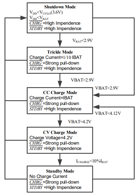
1- The external voltage VCC (USB charging port, 5V power supply) is greater than the voltage lock – in value (3.6V) of TP4056 and the chip CE enable terminal is at a high level; moreover, the external voltage needs to be higher than the battery voltage to activate the TP4056 charging chip.
2- When the battery voltage is lower than 2.9V, pre – charge the battery with a small current first.
3- When the battery voltage is higher than 2.9V, the charging chip charges the battery in constant – current mode, and the current is determined by the charging resistor.
4- When the battery voltage is charged to 4.2V, the charging current gradually decreases, and TP4056 enters the constant – voltage charging mode.
5- When the charging current decreases to the charging termination threshold (1/10 of the constant – current charging current), the charging cycle ends.
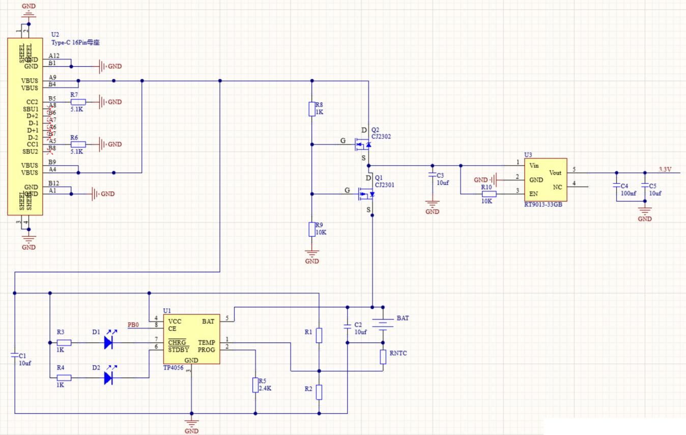
When TP4056 is charging the battery and supplying power to the load at the same time, it is easy to burn out TP4056; so a dual – power automatic selection circuit needs to be added. When the USB is plugged in to charge the battery, the load uses the power from the USB instead of the power from TP4056; when the USB is disconnected, the load uses the battery power.
- When the USB is plugged in, the level between R8 and R9 is high, Q2 is turned on, Q1 is cut off, and the USB charges the battery and supplies power to load U3 at the same time.
- When the USB is not plugged in, the level between R8 and R9 is low, Q2 is cut off, Q1 is turned on, and the battery supplies power to load U3.
If you want to learn more details, you can refer to this Datasheet
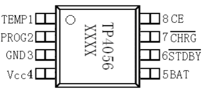
For a simple “charge a battery and power a device” setup, follow this TP4056 wiring diagram:
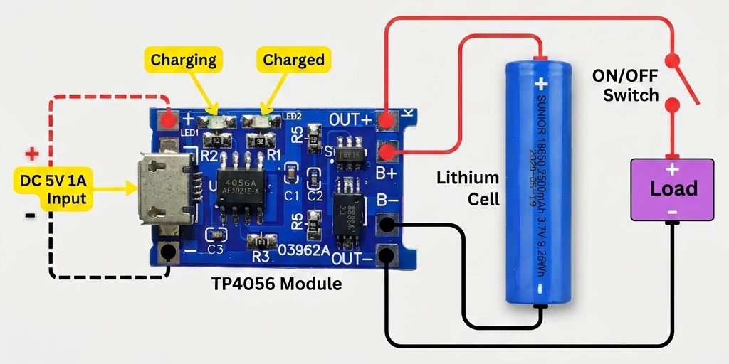
- Integrated charging and discharging, output voltage = battery voltage
- Multiple batteries can be connected in parallel
- Red light on: Charging
- Green light on: Fully charged
- Red and green lights on together or flashing: No battery installed, poor contact, battery damaged, or aged battery.
Comparison between TP4056, TP4054, TP4057 and TP5100
- Cellular Telephones, PDAs, GPS.
- Charging Docks.
- Digital Cameras, Portable Devices.
- USB Bus-Powered Chargers.
وحدة شحن TP4056
قائمة المحتويات
- المقدمة.
- ما هي وحدة شحن TP4056؟
- أهم المميزات التي تجعلها شائعة الاستخدام.
- مقدمة حول خصائص ووظائف شريحة TP4056.
- نظرة عامة على شريحة TP4056.
- الخصائص الأساسية.
- التفاصيل الوظيفية.
- مراحل شحن البطارية باستخدام TP4056.
- المخطط التخطيطي لـ TP4056.
- مواصفات TP4056.
- توزيع الأطراف ومخطط توصيل TP4056.
- دليل التوصيل.
- مقارنة بين TP4056 وTP4054 وTP4057 وTP5100.
- أهم التطبيقات.
- الأسئلة الشائعة.
- الخلاصة.
زمن القراءة حوالي : 15 دقيقة.
المقدمة
إذا كنت تعمل على مشاريع تعتمد على بطاريات الليثيوم، سواء كنت تصمم بنك طاقة بنفسك، أو مشروعًا باستخدام Arduino، أو جهازًا يعمل بالطاقة الشمسية، فمن المحتمل أنك صادفت وحدة شحن TP4056. هذه اللوحة الصغيرة منخفضة التكلفة تُعد من الحلول الشائعة لشحن بطاريات الليثيوم أيون (Li-ion) أو الليثيوم بوليمر (LiPo) بطريقة سهلة وموثوقة. ومع كثرة المصطلحات المرتبطة بها، مثل TP4056 وTP4057، ومخططات التوصيل، ومحولات رفع الجهد، وحماية البطارية، قد يبدو التعامل معها معقدًا في البداية.
في هذا الدليل، سنتعرف على وحدة TP4056 بشكل واضح ومتكامل، بدءًا من أهم مواصفاتها وتوزيع أطرافها، مرورًا بطريقة التوصيل ومراحل الشحن، ووصولًا إلى التطبيقات العملية والبدائل المتاحة. وبذلك ستتمكن من استخدام هذه الوحدة بثقة في مشاريعك الإلكترونية المختلفة.
ما هي وحدة شحن TP4056؟
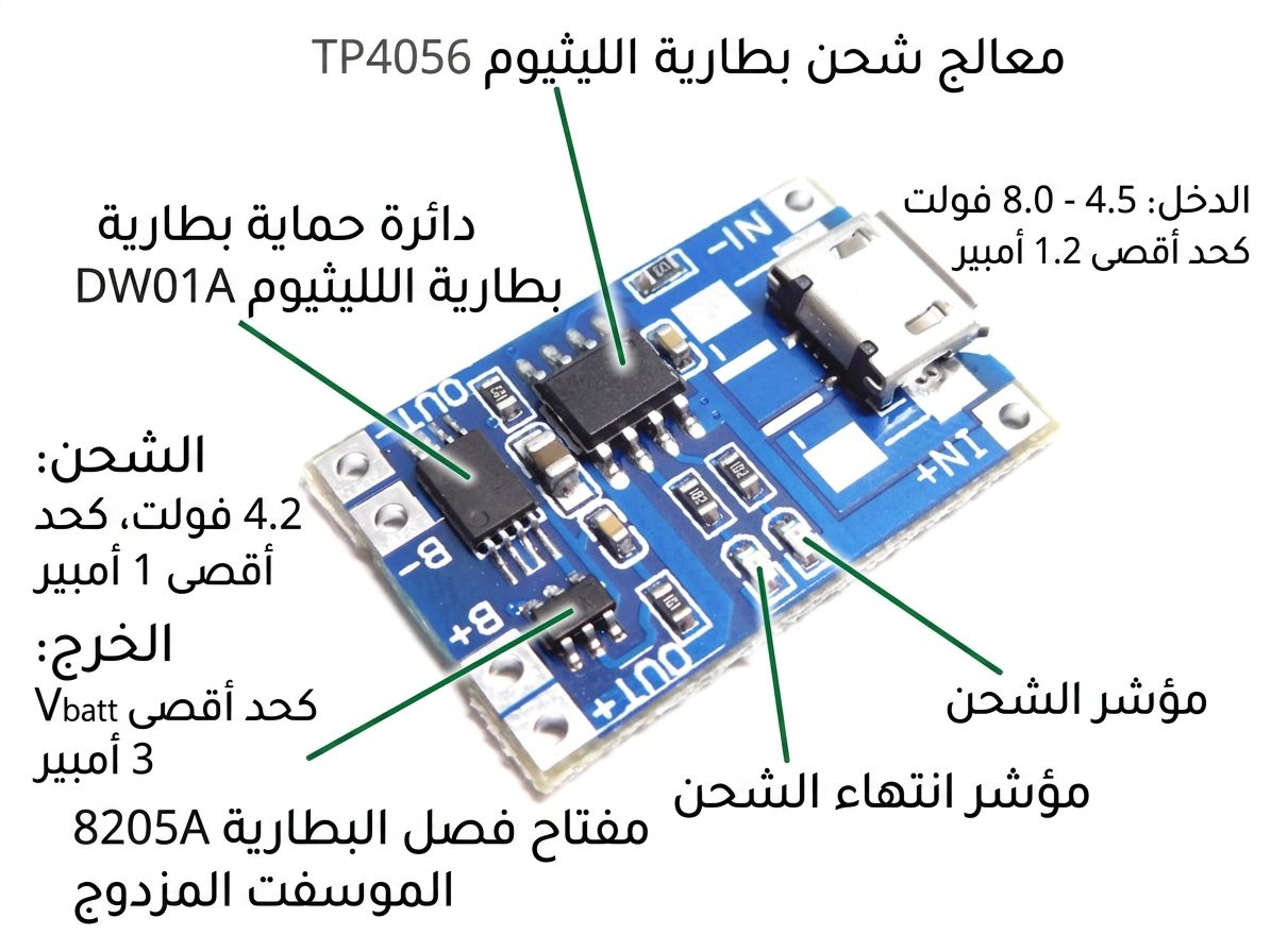
وحدة شحن TP4056
وحدة TP4056 هي لوحة شحن صغيرة وجاهزة للاستخدام تعتمد على شريحة TP4056 IC، وهي شريحة شحن خطية متخصصة في شحن بطاريات الليثيوم أيون والليثيوم بوليمر أحادية الخلية، والتي يبلغ جهدها الاسمي عادةً 3.7V. وعلى عكس دوائر الشحن التي تحتاج إلى تصميم وتجميع العديد من المكونات بشكل منفصل، تأتي وحدة TP4056 مجهزة مسبقًا بالمكونات الأساسية مثل المقاومات والمكثفات ومؤشرات LED، مما يجعلها سهلة الاستخدام دون الحاجة إلى خبرة متقدمة في تصميم دوائر الشحن.
أهم المميزات التي تجعلها شائعة الاستخدام
- تدعم بطاريات الليثيوم أيون والليثيوم بوليمر أحادية الخلية بجهد اسمي 3.7V.
- توفر تيار شحن يصل إلى 1A.
- تعتمد على مرحلتي الشحن بالتيار الثابت والجهد الثابت.
- توقف عملية الشحن تلقائيًا عند وصول البطارية إلى مستوى الشحن الكامل.
- توفر حماية من الشحن الزائد لزيادة أمان البطارية.
- تصميم مدمج يوفر المساحة داخل المشاريع الإلكترونية.
- مناسبة للمشاريع الإلكترونية DIY والأجهزة المحمولة والمشاريع التي تعمل بالبطاريات.
- سهلة الدمج مع مشاريع Arduino وESP32 وغيرها من مشاريع المتحكمات الدقيقة.
- توفر حلًا منخفض التكلفة لشحن بطاريات Li-ion وLiPo أحادية الخلية.
- تحتوي على مؤشرات LED توضح حالة الشحن وحالة اكتمال الشحن.
- يمكن ضبط تيار الشحن من خلال تغيير مقاومة تحديد التيار الخاصة بشريحة TP4056.
- يمكن استخدامها مع مصادر طاقة USB ومصادر DC وفق تصميم الوحدة.
- يمكن إضافة دائرة حماية للبطارية باستخدام شريحة حماية مثل DW01A.
مقدمة حول خصائص ووظائف شريحة TP4056
شريحة TP4056 ووظائفها الأساسية
نظرة عامة على شريحة TP4056
تُعد شريحة TP4056 من الشرائح المتخصصة في إدارة عملية شحن بطاريات الليثيوم أيون، وتُستخدم على نطاق واسع في مختلف تطبيقات الشحن. تحتوي الشريحة على مجموعة من وظائف التحكم والحماية، ولذلك فهي مناسبة للأجهزة المحمولة التي تعتمد على منافذ USB أو محولات الطاقة. كما تجمع في شريحة واحدة وظائف تنظيم تيار الشحن، ومراقبة حالة الشحن، ومجموعة من آليات الحماية الأساسية للبطارية.
الخصائص الأساسية
تشمل أهم الخصائص الأساسية لشريحة TP4056 ما يلي:
- الشحن بتيار ثابت (CC).
- الشحن بجهد ثابت (CV).
- إيقاف عملية الشحن تلقائيًا عند اكتمال الشحن.
- حماية من الشحن الزائد عند انخفاض تيار الشحن إلى مستوى الإنهاء المحدد.
- الحماية من القصر وارتفاع درجة الحرارة.
التفاصيل الوظيفية
وضع الشحن بالتيار الثابت
في مرحلة الشحن بالتيار الثابت، تحافظ TP4056 على تيار شحن محدد وثابت حتى يقترب جهد البطارية من جهد إنهاء الشحن المحدد. تساعد هذه المرحلة على تسريع عملية الشحن مع تقليل التأثيرات السلبية على البطارية.
وضع الشحن بالجهد الثابت
عندما يصل جهد البطارية إلى جهد إنهاء الشحن المحدد مسبقًا، تنتقل TP4056 تلقائيًا إلى وضع الجهد الثابت. في هذه المرحلة تحافظ الشريحة على جهد ثابت، بينما ينخفض تيار الشحن تدريجيًا حتى تنتهي دورة الشحن.
الحماية من الشحن الزائد
تعتمد TP4056 على دائرة لمراقبة الجهد للتحكم في عملية الشحن. وعند وصول البطارية إلى جهد الشحن النهائي، تتوقف عملية الشحن تلقائيًا، مما يساعد على منع استمرار الشحن بعد اكتمال البطارية.
الحماية من القصر وارتفاع درجة الحرارة
تساعد وظيفة الحماية من القصر على الاستجابة بسرعة عند حدوث قصر في خرج الدائرة، مما يحد من التيار ويقلل احتمالية تلف المكونات. كما تراقب وظيفة الحماية الحرارية درجة حرارة الشريحة أثناء التشغيل، وتعمل على تقليل تيار الشحن عند ارتفاع درجة الحرارة بشكل مفرط للمساعدة في حماية الدائرة.
يوضح هذا القسم الخصائص الأساسية والوظائف الرئيسية لشريحة TP4056، وهو ما يساعد على فهم طريقة عملها في عملية شحن بطاريات الليثيوم أيون. وفي القسم التالي، سنتعرف بالتفصيل على مراحل الشحن ودور شريحة TP4056 في كل مرحلة.
مراحل شحن البطارية باستخدام TP4056
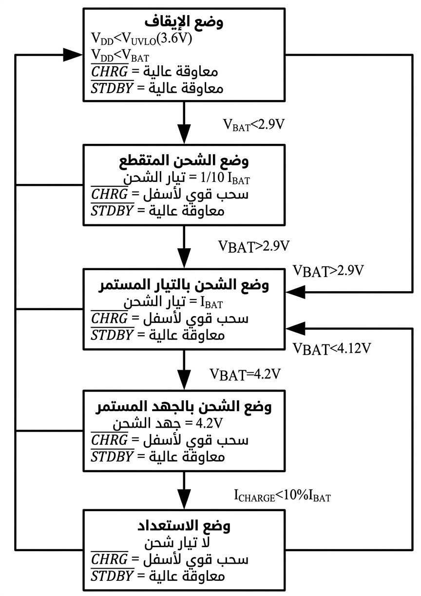
مخطط مراحل شحن البطارية باستخدام TP4056
- يجب أن يكون جهد التغذية الخارجي VCC، مثل منفذ USB أو مصدر 5V، أعلى من قيمة قفل الجهد الخاصة بشريحة TP4056 والتي تبلغ حوالي 3.6V، كما يجب أن يكون طرف التمكين CE في المستوى المرتفع. كذلك يجب أن يكون جهد مصدر التغذية أعلى من جهد البطارية حتى تبدأ عملية الشحن.
- عندما يكون جهد البطارية أقل من 2.9V، تبدأ الشريحة بشحن البطارية بتيار منخفض تمهيديًا.
- عندما يتجاوز جهد البطارية 2.9V، تنتقل الشريحة إلى وضع الشحن بالتيار الثابت، ويتم تحديد تيار الشحن بواسطة مقاومة تحديد التيار.
- عندما يصل جهد البطارية إلى 4.2V، يبدأ تيار الشحن في الانخفاض تدريجيًا، وتنتقل TP4056 إلى مرحلة الشحن بالجهد الثابت.
- عندما ينخفض تيار الشحن إلى حد إنهاء الشحن، والذي يعادل تقريبًا عُشر تيار الشحن في وضع التيار الثابت، تنتهي دورة الشحن.
المخطط التخطيطي لـ TP4056
المخطط التخطيطي لدائرة TP4056
عند استخدام TP4056 لشحن البطارية وفي الوقت نفسه تشغيل حمل كهربائي متصل بها، قد تتعرض الشريحة لإجهاد حراري مرتفع، لذلك يُفضل استخدام دائرة لاختيار مصدر الطاقة تلقائيًا. عند توصيل USB، يحصل الحمل على الطاقة من مصدر USB بدلًا من سحبها مباشرة من دائرة الشحن. وعند فصل USB، ينتقل مصدر الطاقة تلقائيًا إلى البطارية.
- عند توصيل USB، يصبح الجهد بين R8 وR9 مرتفعًا، فيعمل Q2 ويتوقف Q1 عن العمل، وبذلك يقوم USB بشحن البطارية وتغذية الحمل U3 في الوقت نفسه.
- عند فصل USB، يصبح الجهد بين R8 وR9 منخفضًا، فيتوقف Q2 عن العمل ويعمل Q1، وبذلك توفر البطارية الطاقة للحمل U3.
مواصفات TP4056
| المعلمة | القيمة | الوحدة |
|---|---|---|
| جهد طرف VCC | -0.3 إلى 6.5 | V |
| جهد أطراف PROG وBAT وCE وTEMP | -0.3 إلى 6.5 | V |
| جهد طرف CHRG | -0.3 إلى 8 | V |
| جهد طرف STDBY | -0.3 إلى 8 | V |
| تيار طرف BAT | 1 | A |
| تيار طرف PROG | 2 | mA |
| القدرة القصوى المبددة | 1500 | mW |
| درجة حرارة التشغيل المحيطة | -40 إلى 85 | °C |
| درجة حرارة التخزين | -65 إلى 125 | °C |
لمزيد من التفاصيل حول الشريحة، يمكنك الرجوع إلى ورقة البيانات Datasheet.
توزيع الأطراف
توزيع أطراف شريحة TP4056
| الطرف | الوظيفة والوصف |
|---|---|
| TEMP (Pin 1) | مدخل استشعار درجة الحرارة. يمكن توصيل طرف TEMP بخرج الثرمستور NTC الموجود في حزمة بطارية الليثيوم أيون. إذا انخفض جهد TEMP عن 45% أو ارتفع عن 80% من جهد التغذية، تعتبر درجة حرارة البطارية خارج النطاق الآمن ويتم تعليق الشحن. ويمكن تعطيل وظيفة استشعار درجة الحرارة من خلال توصيل طرف TEMP بالأرضي. |
| PROG (Pin 2) | طرف ضبط ومراقبة تيار الشحن. يتم تحديد تيار الشحن من خلال توصيل مقاومة RISET بين هذا الطرف والأرضي. أثناء الشحن بالتيار الثابت، يكون جهد هذا الطرف منظمًا عند حوالي 1V. ويمكن استخدام جهد طرف PROG لمراقبة تيار الشحن وفق العلاقة: IBAT = (VPROG / RPROG) × 1100. |
| GND (Pin 3) | طرف الأرضي. |
| VCC (Pin 4) | مدخل جهد التغذية الموجب. يوفر الطاقة اللازمة لتشغيل دائرة الشحن. عندما يصبح جهد VCC قريبًا جدًا من جهد BAT، تدخل الشريحة في وضع الإيقاف ويصبح تيار طرف BAT منخفضًا جدًا. |
| BAT (Pin 5) | طرف توصيل البطارية. يتم توصيل الطرف الموجب للبطارية بهذا الطرف. يوفر BAT تيار الشحن للبطارية وينظم جهد الشحن النهائي عند 4.2V. يكون التيار المسحوب من هذا الطرف منخفضًا جدًا أثناء وضع التعطيل أو السكون. |
| STDBY (Pin 6) | خرج مفتوح المصرف Open-Drain للإشارة إلى حالة الشحن. عند اكتمال دورة شحن البطارية، يتم سحب هذا الطرف إلى المستوى المنخفض بواسطة مفتاح داخلي، وفي غير ذلك يكون الطرف في حالة ممانعة عالية. |
| CHRG (Pin 7) | خرج مفتوح المصرف Open-Drain للإشارة إلى حالة الشحن. أثناء شحن البطارية، يتم سحب هذا الطرف إلى المستوى المنخفض بواسطة مفتاح داخلي، بينما يكون في حالة ممانعة عالية عند عدم وجود عملية شحن. |
| CE (Pin 8) | مدخل تمكين الشريحة. يؤدي وضع CE في المستوى المرتفع إلى تشغيل الشريحة في الوضع الطبيعي، بينما يؤدي سحب CE إلى المستوى المنخفض إلى إدخال TP4056 في وضع الإيقاف. ويمكن التحكم في CE باستخدام مستويات منطقية TTL أو CMOS. |
ومخطط توصيل TP4056
لإنشاء دائرة بسيطة تقوم بشحن البطارية وتوفير الطاقة لجهاز في الوقت نفسه، يمكن الاستعانة بمخطط توصيل TP4056 المناسب.
مخطط توصيل وحدة TP4056
- يمكن دمج الشحن والتفريغ في الدائرة، ويكون جهد الخرج مساويًا لجهد البطارية.
- يمكن توصيل عدة بطاريات على التوازي عند توافقها مع متطلبات الدائرة.
- إضاءة المؤشر الأحمر: البطارية قيد الشحن.
- إضاءة المؤشر الأخضر: اكتمل شحن البطارية.
- إضاءة المؤشرين الأحمر والأخضر معًا أو وميضهما: قد يشير ذلك إلى عدم تركيب البطارية، أو ضعف التلامس، أو تلف البطارية، أو انتهاء عمرها الافتراضي.
مقارنة بين TP4056 وTP4054 وTP4057 وTP5100
| المعلمة | TP4056 | TP4054 | TP4057 | TP5100 |
|---|---|---|---|---|
| تيار الشحن | حتى 1A، قابل للضبط. | حتى 500mA، ثابت. | حتى 1A، ثابت. | حتى 2A، قابل للضبط. |
| جهد الإدخال | 4.5V–8V. | 4.5V–6V. | 4.5V–8V. | 4.75V–12V. |
| البطاريات المدعومة | بطارية Li-ion أو LiPo أحادية الخلية. | بطارية Li-ion أو LiPo أحادية الخلية. | بطارية Li-ion أو LiPo أحادية الخلية. | بطارية Li-ion أو LiPo أحادية الخلية. |
| الحماية | أساسية، للحماية من الشحن الزائد. | أساسية، للحماية من الشحن الزائد. | أساسية، للحماية من الشحن الزائد. | متقدمة، تشمل الشحن الزائد والتفريغ الزائد والقصر. |
| مشاركة الحمل | اختيارية. | غير متوفرة. | غير متوفرة. | مدمجة. |
| أفضل استخدام | المشاريع العامة، Arduino وبنوك الطاقة. | الأجهزة منخفضة الاستهلاك والأجهزة القابلة للارتداء. | مشاريع الشحن الثابت بتيار 1A. | الأجهزة عالية القدرة، وشواحن الطاقة الشمسية والأجهزة اللوحية. |
الخلاصة من المقارنة: تُعد TP4056 خيارًا عمليًا ومتعدد الاستخدامات للهواة والمشاريع الإلكترونية، لأنها تجمع بين إمكانية ضبط تيار الشحن والتكلفة المنخفضة ودعم بطاريات Li-ion وLiPo أحادية الخلية. أما المشاريع التي تحتاج إلى قدرة شحن أعلى فيمكن أن تستفيد من TP5100، بينما تناسب TP4054 التطبيقات الصغيرة منخفضة التيار.
أهم التطبيقات
- الهواتف المحمولة وأجهزة PDA وأجهزة GPS.
- قواعد ومحطات شحن البطاريات.
- الكاميرات الرقمية والأجهزة المحمولة.
- شواحن البطاريات التي تعمل عبر منفذ USB.
- مشاريع Arduino والأجهزة الإلكترونية المحمولة.
- بنوك الطاقة ومشاريع البطاريات القابلة لإعادة الشحن.
الأسئلة الشائعة
هل يمكن شحن بطاريات الليثيوم مباشرةً من منفذ USB؟
- جهد الإنهاء القياسي لشحن بطاريات الليثيوم هو 4.2V، بينما يوفر منفذ USB القياسي جهدًا يبلغ 5V. لذلك فإن توصيل البطارية مباشرةً بمنفذ USB قد يؤدي إلى شحن زائد، مما قد يتسبب في انتفاخ البطارية أو تلفها.
- قد يكون تيار مصدر USB أعلى من تيار الشحن المسموح به للبطارية، وعدم توافق تيار الشحن قد يؤدي إلى تلف البطارية أو تفعيل حماية التيار الزائد في دائرة الحماية.
- تحتاج بطاريات الليثيوم إلى إدارة دقيقة لعملية الشحن التي تمر عادةً بمراحل التيار الثابت ثم الجهد الثابت ثم إنهاء الشحن. لذلك فإن التوصيل المباشر لا يوفر إدارة الشحن المطلوبة.
ما وظيفة لوحة الحماية الصغيرة الموجودة على بطارية الليثيوم؟ وهل يمكن استخدامها للشحن؟
- لا تُستخدم لوحة الحماية لشحن البطارية، وإنما وظيفتها الأساسية هي حماية البطارية من ظروف التشغيل غير الآمنة.
- الحماية من الشحن الزائد: عند تجاوز جهد الشحن الحد الآمن، مثل 4.25V في بعض دوائر الحماية، يتم فصل دائرة الشحن.
- الحماية من التفريغ الزائد: عندما ينخفض جهد البطارية عن جهد الفصل المحدد، مثل 2.5V في بعض الدوائر، يتم فصل دائرة التفريغ.
- الحماية من القصر: تعمل الدائرة على فصل التيار بسرعة عند حدوث قصر كهربائي.
ما هو جهد الشحن العائم؟
عندما تصل البطارية إلى الشحن الكامل، لا يعني ذلك بالضرورة أن دائرة الشحن تتوقف عن مراقبتها بشكل كامل. في بعض أنظمة الشحن يتم الحفاظ على جهد محدد مع تيار منخفض جدًا لتعويض التفريغ الطبيعي للبطارية. ويُقصد بجهد الشحن العائم الجهد الذي تحافظ عليه دائرة الشحن بعد وصول البطارية إلى حالة الشحن الكامل.
لماذا قد يصبح وقت الشحن أطول عند زيادة جهد دخل TP4056؟
إذا ارتفع جهد دخل TP4056 بشكل ملحوظ، مثل 5.2V أو 5.5V، فقد ينخفض تيار الشحن عن القيمة الاسمية البالغة 1A. ويُعد ذلك أمرًا طبيعيًا في بعض ظروف التشغيل، لأن ارتفاع فرق الجهد عبر الشريحة يؤدي إلى زيادة الحرارة، ولذلك تقوم الشريحة بتقليل تيار الشحن للمساعدة في الحد من ارتفاع درجة الحرارة وحماية الدائرة.
هل يمكن للبطارية أن تشحن وتغذي المكونات الأخرى في الوقت نفسه بعد توصيل USB؟
لا يُنصح بتوصيل الحمل مباشرة بطريقة تجعل TP4056 مسؤولة عن شحن البطارية وتشغيل الحمل في الوقت نفسه، لأن الحمل قد يسبب إجهادًا حراريًا زائدًا على الشريحة. وللحصول على تشغيل أكثر أمانًا، يمكن استخدام دائرة لإدارة مصدر الطاقة تلقائيًا. عند توصيل USB يتم اختيار USB كمصدر للطاقة، وعند فصله يتم الانتقال تلقائيًا إلى البطارية.
الخلاصة
تُعد وحدة شحن TP4056 حلًا منخفض التكلفة وصغير الحجم وسهل الاستخدام لشحن بطاريات Li-ion وLiPo أحادية الخلية. وبفضل إمكانية ضبط تيار الشحن، ومؤشرات حالة الشحن، وإمكانية إضافة دائرة حماية للبطارية، فهي مناسبة للعديد من المشاريع الإلكترونية مثل الأجهزة المحمولة وبنوك الطاقة ومشاريع Arduino. كما أن تصميمها البسيط وسهولة دمجها في الدوائر يجعلها خيارًا عمليًا للمبتدئين والمستخدمين ذوي الخبرة في مجال الإلكترونيات.


Leave a comment
You must be logged in to post a comment.