


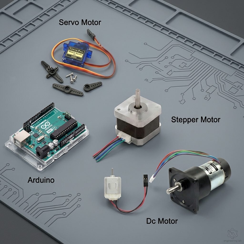
Arduino – Motors Connections, Control and Programming
Contents List
- Introduction of Arduino.
- Introduction of Motors.
- Difference between DC Motor vs Servo Motor vs Stepper Motor.
- Why Can’t We Connect a Motor Directly to an Arduino?
- Protecting the Arduino and Circuit.
- Arduino – Servo Motor Connections, Control and Programming.
- Introduction of Servo Motor.
- What Is a Servo Motor?
- Pin Configuration of Servo Motor.
- How Servo Motor work?
- How Do You Communicate the Angle at Which the Servo Should Turn?
- Important Power Considerations.
- Common Applications of Servo Motor.
- Components Required.
- Connecting the Servo Motor to Arduino.
- Example of Arduino – Servo Motor Connection.
- Controlling a Servo Motor with Arduino.
- Controlling the Servo Movement Speed.
- Useful Arduino Servo Functions.
- Using Multiple Servo Motors.
- Common Problems and Important Precautions.
- Arduino – DC Motor Connections, Control and Programming.
- Introduction of DC Motor.
- Pin Configuration of DC Motor.
- Common Applications of DC Motor.
- Important Power Considerations
- How to Control a DC Motor?
- L298N Motor Driver.
- Connecting Arduino to the L298N.
- Controlling DC Motor Direction.
- Controlling DC Motor Speed.
- Example of Arduino – DC Motor Connection.
- Common Problems and Important Precautions
- Arduino – Stepper Motor Connections, Control and Programming.
- Introduction of Stepper Motor.
- What Is a Stepper Motor?
- How a Stepper Motor Works?
- Why a Stepper Motor Driver Is Required?
- Common Applications of Stepper Motor.
- Examples of Stepper Motor Drivers
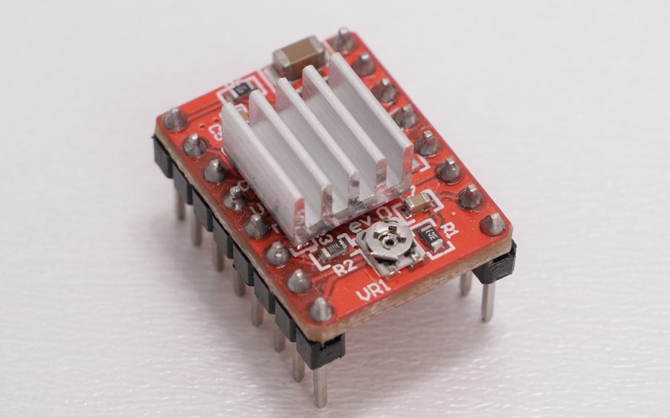
- A4988 Stepper Motor Driver.
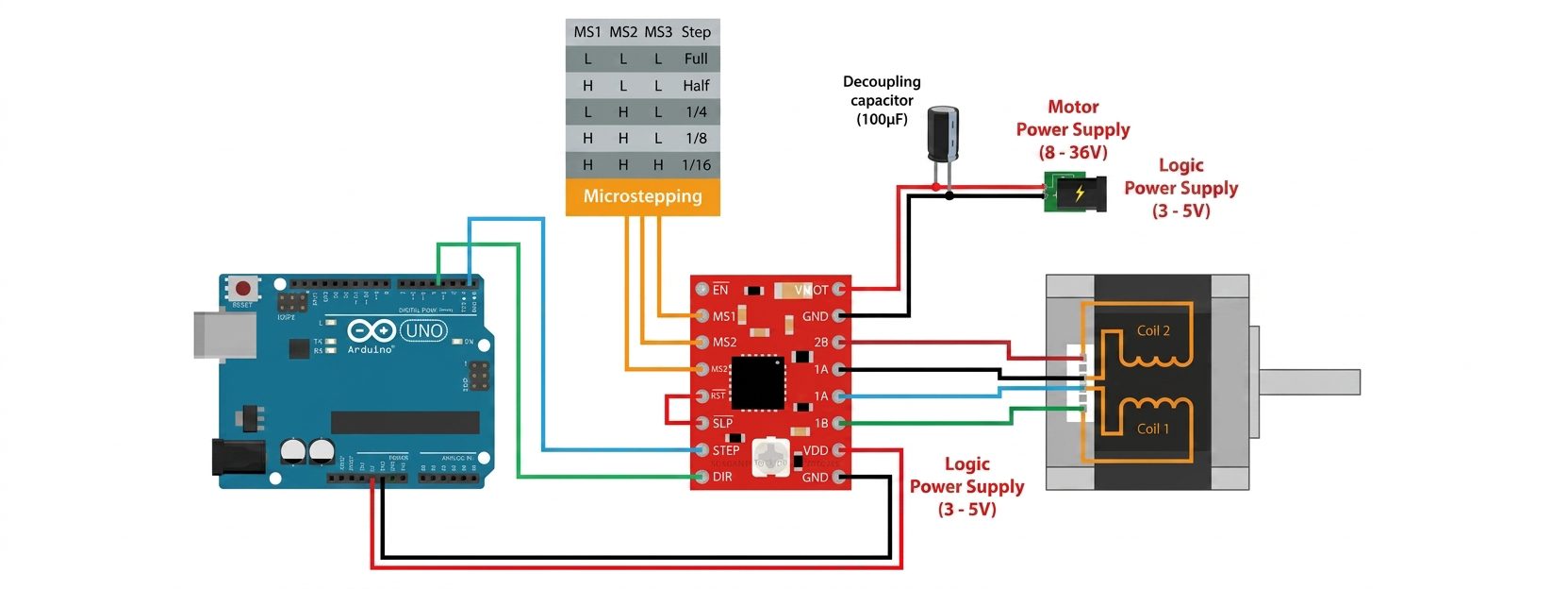
- Connecting Arduino to the A4988 Driver.
- Motor Power and Current Limit.
- Microstepping.
- Controlling the Motor with Arduino.
- Controlling Speed and Direction.
- Using the AccelStepper Library.
- Common Problems and Important Precautions.
- Which Motor Should You Choose?
- Conclusion.
Reading Time Approximately is 20 minute
Introduction of Arduino
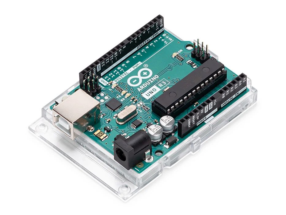
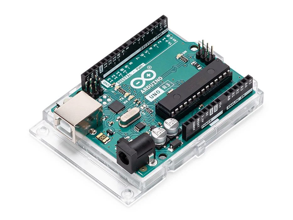
Arduino Uno is a microcontroller board based on the ATmega328P (Datasheet). It has 14 digital input/output pins (of which 6 can be used as PWM outputs), 6 analog inputs, a 16 MHz ceramic resonator (CSTCE16M0V53-R0), a USB connection, a power jack, an ICSP header and a reset button. It contains everything needed to support the microcontroller; simply connect it to a computer with a USB cable or power it with a AC-to-DC adapter or battery to get started.. You can tinker with your Uno without worrying too much about doing something wrong, worst case scenario you can replace the chip for a few dollars and start over again.
“Uno” means one in Italian and was chosen to mark the release of Arduino Software (IDE) 1.0. The Uno board and version 1.0 of Arduino Software (IDE) were the reference versions of Arduino, now evolved to newer releases. The Uno board is the first in a series of USB Arduino boards, and the reference model for the Arduino platform; for an extensive list of current, past or outdated boards see the Arduino index of boards.
Introduction of Motors
Motors are one of the most useful components in Arduino projects. They allow a project to move, rotate, position, open, close, or control mechanical parts. However, connecting a motor to an Arduino is different from connecting a simple LED or sensor because motors usually require more current than an Arduino pin can safely provide.
In this article, we will look at the three motor types commonly used with Arduino:

Difference between Servo Motor vs DC Motor vs Stepper Motor
| Parameter | DC Motor | Servo Motor | Stepper Motor |
|---|---|---|---|
| Basic operation | Rotates continuously when powered | Rotates to a commanded position | Rotates in fixed angular steps |
| Position control | No built-in position control | Excellent | Good, but usually open-loop |
| Speed control | Easy using PWM | Easy and precise | Good, but limited at high speeds |
| Direction control | Reversed by changing polarity | Controlled electronically | Controlled electronically |
| Feedback | Usually none | Usually has encoder/potentiometer feedback | Usually no feedback |
| Control method | Voltage/PWM | PWM or control signal | Pulse and direction signals |
| Accuracy | Low for positioning | High | High for incremental positioning |
| Torque at low speed | Moderate | High | High |
| Continuous rotation | Excellent | Possible, depending on type | Possible, but less efficient at high speed |
| Speed range | High | High | Moderate |
| Holding position | Poor without feedback/control | Excellent | Excellent when energized |
| Control complexity | Simple | Moderate | Moderate |
| Driver required | Usually simple Driver/transistor or H-bridge | Servo controller/Driver | Stepper Driver |
| Typical applications | Fans, pumps, wheels, toys | Robotics, RC systems, CNC, pan/tilt mechanisms | 3D printers, CNC, positioning systems |
| Main advantage | Simple and inexpensive continuous rotation | Precise position, speed, and torque control | Precise step-by-step movement |
| Main disadvantage | Cannot accurately control position without feedback | More expensive and complex | Can lose steps if overloaded |
Why Can’t We Connect a Motor Directly to an Arduino?
An Arduino GPIO pin is intended to control electronic signals and small loads. A motor can require considerably more current, especially when starting or when mechanically loaded.
Connecting a motor directly to an Arduino pin can:
- Exceed the pin’s current capability
- Cause voltage drops and Arduino resets
- Generate electrical noise
- Damage the Arduino
Therefore, a motor driver or other suitable interface is normally required.
The general arrangement is:
Arduino → Motor Driver/Control Circuit → Motor
The motor should also have an appropriate power supply. In many projects, the motor power supply is separate from the Arduino’s power supply.
Protecting the Arduino and Circuit
Motors are inductive loads and can produce voltage spikes when their current changes. Proper motor-driver circuits normally include protection against these effects. For a discrete transistor or MOSFET circuit driving a brushed DC motor, a suitable flyback diode is typically required.
There are several other important precautions:
- Check the motor’s rated voltage.
- Check its operating and stall current.
- Use a motor driver rated for the motor.
- Use an adequate external power supply when necessary.
- Connect grounds correctly.
- Do not draw motor current through an Arduino GPIO pin.
- Check the driver’s thermal limits.
The motor’s stall current is particularly important because it can be much higher than the current consumed by the motor while it is spinning freely.
Arduino – Servo Motor Connections, Control and Programming
Introduction of Servo Motor
A servo motor is an actuator that allows an Arduino to control the angular position of a mechanical shaft. Unlike a conventional DC motor, a standard servo motor can be commanded to move to a specific angle, typically within a range of 0° to 180°.
What Is a Servo Motor?
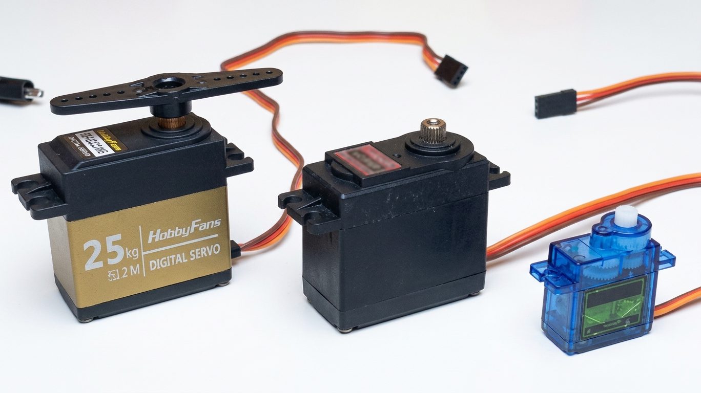
A Servo Motor is a small device that has an output shaft. This shaft can be positioned to specific angular positions by sending the servo a coded signal. As long as the coded signal exists on the input line, the servo will maintain the angular position of the shaft. If the coded signal changes, the angular position of the shaft changes.
The Types of Servo Motor :
- 90° Servo Motor.
- 180° Servo Motor.
- 360° Servo Motor.
The 360° Servo Motor is similar to DC motor, except for no hardware driver is required.
This makes a servo different from a standard DC motor. A DC motor is generally used when you want continuous rotation, while a standard servo is useful when you want to position something at a particular angle.
A servo motor is one of the easiest motors to control with an Arduino. Unlike a regular DC motor, a servo motor can be commanded to move to a specific angle, making it useful for robotics, automation, remote-controlled projects, and many other Arduino applications.
Pin Configuration of Servo Motor
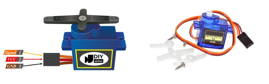
Most small hobby servo motors have three wires.
The wire colors can vary between manufacturers, so always check the documentation for your particular servo. A common color arrangement is:
| Servo Motor Wire | Function | Arduino Connection |
|---|---|---|
| Red | VCC / Power | Suitable 5 V supply |
| Brown or Black | GND | Arduino GND |
| Orange or Yellow | Signal | Arduino digital pin |
The three connections have different purposes.
VCC
- The VCC wire supplies power to the servo motor.
- Many small hobby servos are designed to operate from approximately 5 V, but the correct voltage depends on the specific servo. Always check the servo’s specifications before connecting a power supply.
GND
- The GND wire is the electrical ground connection.
- If you use an external power supply for the servo, the external supply’s negative terminal should be connected to the Arduino GND. This gives the Arduino and servo a common electrical reference.
Signal
- The signal wire receives the control signal from the Arduino.
- For example, you can connect the signal wire to Arduino digital pin 9 and then use the Arduino Servo library to command the servo to a particular angle.
How Servo Motor work?
The servo motor has some control circuits and a potentiometer (a variable resistor, aka pot) connected to the output shaft. In the picture above, the pot can be seen on the right side of the circuit board. This pot allows the control circuitry to monitor the current angle of the servo motor.
If the shaft is at the correct angle, then the motor shuts off. If the circuit finds that the angle is not correct, it will turn the motor until it is at a desired angle. The output shaft of the servo is capable of traveling somewhere around 180 degrees. Usually, it is somewhere in the 210-degree range, however, it varies depending on the manufacturer. A normal servo is used to control an angular motion of 0 to 180 degrees. It is mechanically not capable of turning any farther due to a mechanical stop built on to the main output gear.
The power applied to the motor is proportional to the distance it needs to travel. So, if the shaft needs to turn a large distance, the motor will run at full speed. If it needs to turn only a small amount, the motor will run at a slower speed. This is called proportional control.

How Do You Communicate the Angle at Which the Servo Should Turn?
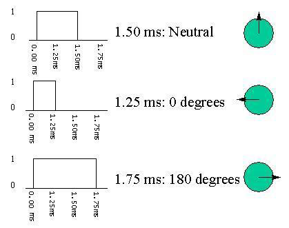
The control wire is used to communicate the angle. The angle is determined by the duration of a pulse that is applied to the control wire. This is called Pulse Coded Modulation. The servo expects to see a pulse every 20 milliseconds (.02 seconds). The length of the pulse will determine how far the motor turns. A 1.5 millisecond pulse, for example, will make the motor turn to the 90-degree position (often called as the neutral position). If the pulse is shorter than 1.5 milliseconds, then the motor will turn the shaft closer to 0 degrees. If the pulse is longer than 1.5 milliseconds, the shaft turns closer to 180 degrees.
Important Power Considerations
Although a servo can sometimes be powered from the Arduino’s 5V output, this is not recommended for higher-current servo applications.
A servo motor can draw significant current, especially when:
- The servo is a high-torque model.
- The servo is carrying a heavy load.
- The servo starts moving.
- The servo is stalled or working against mechanical resistance.
- Several servo motors are used simultaneously.
Insufficient power can cause unstable operation, unexpected resets, or other problems.
For these applications, use a suitable external power supply for the servo.

Important Ground Connection
When an external power supply is used, the negative terminal of the external supply must be connected to the Arduino GND.
This creates a common reference between the Arduino control signal and the servo power supply.
The basic arrangement is:
- External supply positive → Servo VCC
- External supply negative → Servo GND
- External supply negative → Arduino GND
- Arduino digital pin → Servo Signal
Do not connect the positive terminal of the external servo power supply directly to the Arduino 5V pin unless the power arrangement has been specifically designed for that purpose.
Common Applications of Servo Motor
- Robotic Arms.
- Robot steering systems.
- Pan-and-tilt mechanisms.
- Camera platforms.
- Automatic doors and locks.
- Model vehicles.
- Mechanical control systems.
Components Required
For a basic Arduino servo project, you will need:
- Arduino Uno or compatible Arduino board
- Standard servo motor
- USB cable
- Jumper wires
- Suitable power supply for the servo
- Breadboard, if required
For projects using a high-torque servo or multiple servo motors, an external power supply is recommended.
Connecting the Servo Motor to Arduino
Basic Signal Connection
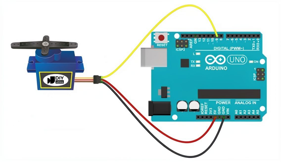
Connect the servo motor as follows:
| Servo Motor Connection | Arduino Connection |
| Signal | Digital pin 9 |
| GND | GND |
| VCC | Appropriate 5V supply |
Example of Arduino – Servo Motor Connection
The following program makes the servo move gradually from 0° to 180° and then back from 180° to 0°.
#include <Servo.h>

Servo servo;

void setup()
{
  servo.attach(9);
  servo.write(0);
}

void loop()
{
  // Move from 0° to 180°
  for (int pos = 0; pos <= 180; pos++)
  {
    servo.write(pos);
    delay(10);
  }

  // Move from 180° back to 0°
  for (int pos = 180; pos >= 0; pos--)
  {
    servo.write(pos);
    delay(10);
  }
}
How the Example Program Works
Step 1: Include the Servo Library
#include <Servo.h>This makes the Arduino Servo library available to the program.
Step 2: Create a Servo Object
Servo servo;The servo object represents the servo motor that will be controlled by the program.
If multiple servos are used, multiple Servo objects can be created.
For example:
Servo servo1;
Servo servo2;
Step 3: Attach the Servo to an Arduino Pin
servo.attach(9);This assigns Arduino digital pin 9 as the control pin for the servo.
The servo’s signal wire should therefore be connected to pin 9.
Step 4: Set the Initial Position
servo.write(0);This commands the servo to move toward the 0° position.
Step 5: Move from 0° to 180°
for (int pos = 0; pos <= 180; pos++)
{
  servo.write(pos);
  delay(10);
}
The variable pos starts at 0 and increases one degree at a time until it reaches 180.
The servo.write(pos) command sends the requested position to the servo.
The delay(10) introduces a short delay between position commands, producing a gradual movement.
Step 6: Move from 180° to 0°
for (int pos = 180; pos >= 0; pos--)
{
  servo.write(pos);
  delay(10);
}
The same process is repeated in reverse, causing the servo to return gradually from 180° to 0°.
Uploading the Program to Arduino
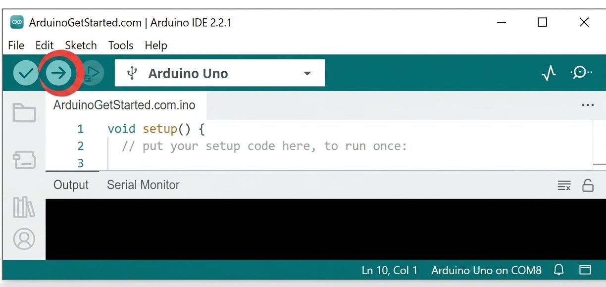
Follow these steps to run the project:
- Connect the Arduino board to the computer using a USB cable.
- Open the Arduino IDE.
- Select the correct Arduino board.
- Select the correct communication port.
- Create a new sketch.
- Copy the servo control program into the sketch.
- Verify/compile the program.
- Upload the program to the Arduino.
- Observe the servo motor.
Expected Result
After the program is uploaded, the servo should repeatedly:
0° → 180° → 0°
The movement occurs gradually because the program changes the requested position in small one-degree steps and introduces a short delay between the commands.
Controlling a Servo Motor with Arduino
Arduino provides a Servo library that makes controlling a standard servo relatively simple.
Instead of manually generating the control waveform, the program can use functions provided by the library to:
- Create a servo object.
- Assign an Arduino pin to the servo.
- Specify the desired angle.
The main functions used in this basic application are:
#include <Servo.h>

Servo myServo;

myServo.attach(9);

myServo.write(90);
In this example, Arduino uses digital pin 9 as the servo control pin and commands the servo to move to approximately 90°.
Controlling the Servo Movement Speed
The speed of the movement can be influenced by how frequently the target position is updated.
A simple approach is to change the delay:
delay(10);For example:
delay(20);will make the position updates occur less frequently.
However, using delay() blocks the execution of other code while the program waits. For projects where the Arduino must perform other tasks simultaneously, a non-blocking approach using millis() can be used.
Smooth Movement Using millis()
The millis() function allows the Arduino to measure elapsed time without stopping the entire program.
The general approach is:
- Record the starting time.
- Calculate how much time has passed.
- Convert the elapsed time into a corresponding servo angle.
- Update the servo position.
- Continue executing other parts of the program.
The map() function can be used to convert elapsed time into an angle.
Example
#include <Servo.h>

Servo myServo;

unsigned long MOVING_TIME = 3000;
unsigned long moveStartTime;

int startAngle = 30;
int stopAngle = 90;

void setup()
{
  myServo.attach(9);

  moveStartTime = millis();
}

void loop()
{
  unsigned long progress = millis() - moveStartTime;

  if (progress <= MOVING_TIME)
  {
    long angle = map(
      progress,
      0,
      MOVING_TIME,
      startAngle,
      stopAngle
    );

    myServo.write(angle);
  }

  // Other code can run here
}
In this example, the servo moves from 30° to 90° over approximately 3 seconds, while the Arduino remains available to execute other tasks.
Useful Arduino Servo Functions
The Servo library provides several useful functions for controlling and monitoring servo motors.
| Function | Purpose |
Servo.attach() |
Connects a Servo object to a control pin |
Servo.write() |
Commands the servo to a specified angle |
Servo.writeMicroseconds() |
Controls the servo using pulse width in microseconds |
Servo.read() |
Reads the last commanded servo angle |
Servo.attached() |
Checks whether the servo is attached |
Servo.detach() |
Disconnects the Servo object from its control pin |
Using Multiple Servo Motors
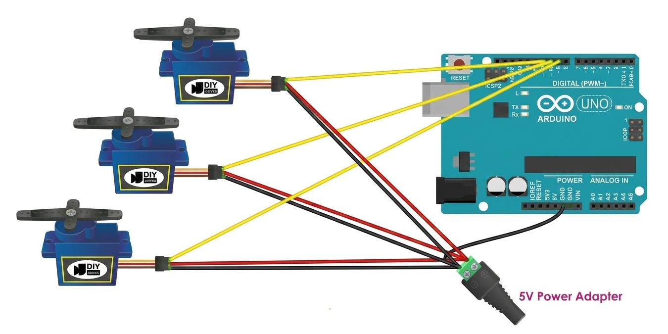
The Arduino Servo library can be used to control multiple servo motors.
For example:
Servo servo1;
Servo servo2;
Each servo can then be attached to its own control pin.
When using several servos, however, the power supply becomes especially important because the total current demand can increase significantly.
For larger numbers of servos, a dedicated servo driver such as a PCA9685 16-channel PWM servo driver can simplify wiring and reduce the number of Arduino pins required.
Common Problems and Important Precautions
Servo Does Not Move
Check the following:
- Verify the servo signal wire is connected to the correct Arduino pin.
- Check the VCC and GND connections.
- Confirm that the servo receives the correct supply voltage.
- Make sure the Arduino code uses the same pin connected to the signal wire.
- Check that the Servo library is included.
Arduino Resets When the Servo Moves
- This can occur when the servo draws more current than the Arduino’s power source can provide.
- A suitable external power supply for the servo may solve the problem.
Servo Behaves Erratically
Check that:
- The servo has a stable power supply.
- Arduino GND and the external power-supply GND are connected together.
- The wiring is secure.
- The servo is not mechanically overloaded.
Arduino – DC Motor Connections, Control and Programming
Introduction of DC Motor
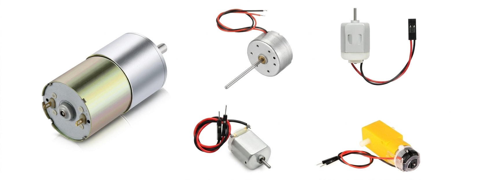
A DC motor converts electrical energy into continuous rotational motion. Arduino can control a DC motor’s speed and direction, but a motor should not be connected directly to an Arduino output pin because the motor requires more current than the Arduino pin can safely provide.
A motor driver is therefore used between the Arduino and the motor. The driver receives low-power control signals from the Arduino and provides the required current to operate the motor.
Pin Configuration of DC Motor
A basic DC motor has two wires:
| Wire | Function |
|---|---|
| Positive | Motor power connection |
| Negative | Motor power connection |
- The direction of rotation depends on the polarity applied to these two wires.
- Reversing the polarity reverses the motor’s direction.

Common Applications of DC Motor
- Robotics and robotic vehicles.
- Electric toys and model vehicles.
- Cooling fans and blowers.
- Pumps and water systems.
- Conveyor systems.
- Automatic doors and gates.
- Small power tools.
- Printers and scanners.
- Camera mechanisms.
- Automotive systems.
- Automated machines and actuators.
- DIY and Arduino projects.
Important Power Considerations
The Arduino output pin provides only a control signal. It should not be used to power the DC motor directly.
Use a suitable motor driver and an appropriate external power supply.
Before connecting the motor, check:
- Motor rated voltage.
- Motor operating current.
- Motor stall current.
- Motor driver voltage and current ratings.
- Power-supply capacity.
A motor can draw significantly more current during startup or when stalled, so the power supply and driver must be selected accordingly.
How to Control a DC Motor?
Two main parameters can be controlled:
Speed
Motor speed can be controlled using PWM (Pulse Width Modulation). A higher PWM duty cycle generally provides higher average power to the motor and therefore higher speed.
Direction
The motor direction is controlled by reversing the polarity applied to the motor. An H-bridge motor driver performs this electronically.
The basic control system is:
Arduino → Motor Driver → DC Motor
L298N Motor Driver
The L298N is a commonly used motor driver that can control up to two DC motors independently.
For each motor, the important pins are:
| L298N Pin | Function |
|---|---|
| ENA | Motor A speed control using PWM |
| IN1 | Motor A direction control |
| IN2 | Motor A direction control |
| OUT1 | Motor A connection |
| OUT2 | Motor A connection |
| VCC | Motor power supply |
| GND | Common ground |
The L298N receives control signals from the Arduino while supplying the required motor current from the motor power source.

Connecting Arduino to the L298N
For Motor A, the following connections can be used:
| Arduino | L298N |
|---|---|
| Digital Pin 9 | ENA |
| Digital Pin 6 | IN1 |
| Digital Pin 5 | IN2 |
| GND | GND |
Connect the DC motor to OUT1 and OUT2.
Connect a suitable external power supply to the motor-power input of the L298N.
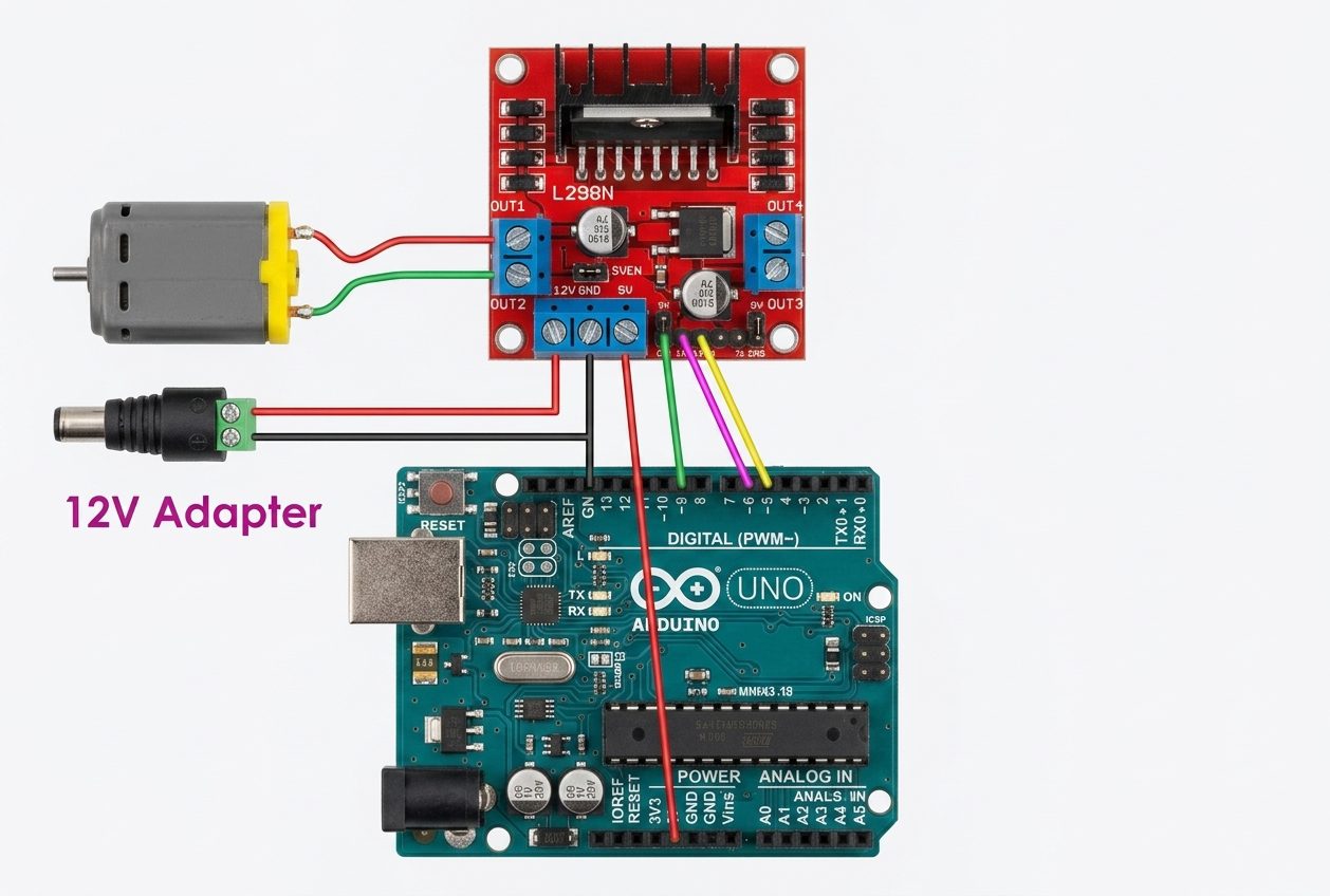
Important: The motor power supply must be suitable for the motor’s rated voltage and current. The Arduino and L298N should share a common ground.
Controlling DC Motor Direction
The direction of Motor A is determined by IN1 and IN2.
| IN1 | IN2 | Motor State |
|---|---|---|
| LOW | LOW | Stop |
| HIGH | HIGH | Stop |
| HIGH | LOW | Direction 1 |
| LOW | HIGH | Direction 2 |
If the actual direction is opposite to the expected direction, swap the motor wires connected to OUT1 and OUT2 or reverse the IN1/IN2 logic in the program.
Controlling DC Motor Speed
Connect the L298N ENA pin to an Arduino PWM-capable pin.
The Arduino analogWrite() function can then control the PWM duty cycle:
analogWrite(ENA_PIN, speed);
On a typical Arduino UNO, the value ranges from 0 to 255:
| PWM Value | Motor Control |
|---|---|
| 0 | Stop |
| 128 | Approximately 50% duty cycle |
| 255 | 100% duty cycle |
The actual motor speed is affected by the motor type, load, supply voltage, and other factors, so PWM value does not represent an exact RPM.
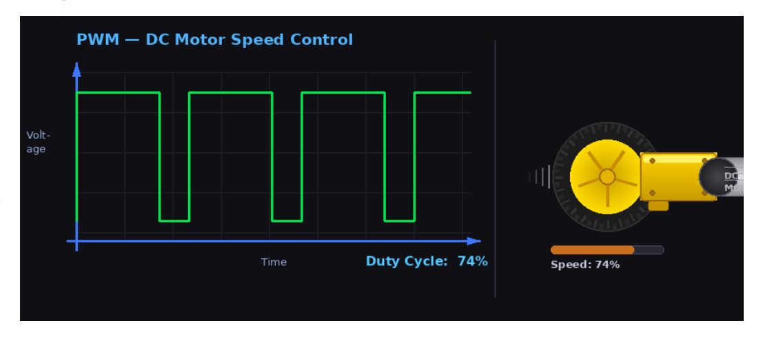
Example of Arduino – DC Motor Connection.
Arduino Code
The following example gradually increases the motor speed, changes direction, gradually decreases the speed, and then stops the motor.
const int ENA_PIN = 9;
const int IN1_PIN = 6;
const int IN2_PIN = 5;

void setup()
{
  pinMode(ENA_PIN, OUTPUT);
  pinMode(IN1_PIN, OUTPUT);
  pinMode(IN2_PIN, OUTPUT);
}

void loop()
{
  // Rotate in Direction 1
  digitalWrite(IN1_PIN, HIGH);
  digitalWrite(IN2_PIN, LOW);

  for (int speed = 0; speed <= 255; speed++)
  {
    analogWrite(ENA_PIN, speed);
    delay(10);
  }

  delay(1000);

  // Change direction
  digitalWrite(IN1_PIN, LOW);
  digitalWrite(IN2_PIN, HIGH);

  delay(1000);

  // Gradually stop
  for (int speed = 255; speed >= 0; speed--)
  {
    analogWrite(ENA_PIN, speed);
    delay(10);
  }

  delay(1000);
}
How the Program Works
The program uses three Arduino pins:
- Pin 9 controls motor speed through PWM.
- Pin 6 controls one direction input.
- Pin 5 controls the other direction input.
First, IN1 is HIGH and IN2 is LOW, causing the motor to rotate in one direction.
The for loop gradually increases the PWM value from 0 to 255, smoothly increasing the motor’s drive.
The direction is then reversed by changing IN1 and IN2.
Finally, the PWM value is gradually reduced from 255 to 0, stopping the motor.
Common Problems and Important Precautions
Motor Does Not Rotate
Check the motor power supply, L298N wiring, Arduino connections, ENA connection, and common ground.
Motor Rotates in the Wrong Direction
Swap the motor wires on OUT1 and OUT2 or reverse the IN1/IN2 logic.
Motor Speed Cannot Be Controlled
Make sure ENA is connected to a PWM-capable Arduino pin and that the ENA jumper configuration is appropriate for PWM control.
Arduino Resets When the Motor Starts
The motor may be drawing excessive current or causing electrical noise. Use a suitable external motor supply and ensure the Arduino and driver have a proper common ground.
Arduino – Stepper Motor Connections, Control and Programming

Which Motor Should You Choose?
The best motor depends on what you need the project to do.
| Motor | Main Advantage | Typical Application |
| Servo Motor | Easy position control | Robotic arm |
| Stepper Motor | Controlled incremental movement | CNC/3D printer |
| DC Motor | Simple continuous rotation | Robot car |
Choose a servo when:
You need to move something to a particular angle and do not need continuous rotation.
Choose a stepper when:
You need controlled incremental rotation and repeatable positioning.
Choose a DC motor when:
You need continuous rotation, such as driving a wheel, fan, or pump.
Conclusion
Connecting a motor to an Arduino is not simply a matter of connecting two wires to a digital pin. The Arduino provides the control signals, while an appropriate driver or control circuit handles the electrical power required by the motor.
The three common approaches are:
Servo Motor : Arduino → Control Signal → Servo Motor
Stepper Motor : Arduino → Stepper Driver → Stepper Motor
DC Motor : Arduino → Motor Driver → DC Motor
Once the correct driver, power supply, and wiring are selected, Arduino can provide precise control over motor position, speed, and direction. This makes motors a powerful building block for robotics, automation, and many other Arduino projects.
Conclusion of Arduino – Servo Moves
A standard servo motor provides a simple way for an Arduino to control angular position. The motor typically has three connections: VCC, GND, and Signal.
The Arduino Servo library simplifies servo control by providing functions such as attach() and write(). Once the servo is connected and the library is included, the Arduino can command the servo to move to different positions.
For basic projects, a servo may be controlled directly from the Arduino’s control pin, but the servo’s power requirements must be considered carefully. High-torque or multiple-servo applications should normally use an appropriate external power supply, with the external supply’s ground connected to the Arduino GND.
The basic control sequence is:
Connect the servo → Include the Servo library → Attach the signal pin → Set the desired angle → Upload the program → Observe the servo movement.
Conclusion of Arduino – DC Motor
Arduino can control a DC motor’s speed and direction, but the motor should be controlled through a suitable motor driver rather than directly from an Arduino output pin.
The L298N provides a simple solution for controlling one or two DC motors. Its ENA input controls speed using PWM, while IN1 and IN2 control the motor’s direction.
The basic system is:
Arduino → L298N Motor Driver → DC Motor
with a suitable external power supply for the motor.
By combining PWM speed control with H-bridge direction control, Arduino can smoothly accelerate, decelerate, reverse, and stop a DC motor.
Conclusion of Arduino – Stepper Motor
A stepper motor provides precise, controlled movement by rotating in discrete steps. Arduino can control it through a dedicated stepper driver such as the A4988.
The basic control system is:
Arduino → STEP/DIR Signals → A4988 Driver → Stepper Motor
The STEP signal controls movement, while DIR controls direction. Microstepping provides smoother movement, and correct current-limit adjustment is essential for safe and reliable operation.
For more advanced applications, libraries such as AccelStepper can provide speed, acceleration, deceleration, and position control.
 
محركات – Arduino : التوصيل والتحكم والبرمجة
قائمة المحتويات
- مقدمة عن لوحة Arduino
- مقدمة عن المحركات
- الفرق بين محرك DC ومحرك Servo ومحرك Stepper.
- لماذا لا يمكن توصيل المحرك مباشرةً بـ Arduino؟
- حماية Arduino والدائرة.
- توصيل محرك Servo مع Arduino والتحكم فيه وبرمجته.
- مقدمة عن محرك Servo.
- ما هو محرك Servo؟
- توصيل أطراف محرك Servo.
- كيف يعمل محرك Servo؟
- كيف يتم إرسال الزاوية المطلوبة إلى محرك Servo؟
- اعتبارات مهمة لمصدر الطاقة.
- الاستخدامات الشائعة لمحرك Servo.
- المكونات المطلوبة.
- توصيل محرك Servo مع Arduino.
- مثال على توصيل محرك Servo مع Arduino.
- التحكم في محرك Servo باستخدام Arduino.
- التحكم في سرعة حركة محرك Servo.
- دوال Arduino المفيدة لمحرك Servo.
- استخدام عدة محركات Servo.
- المشكلات الشائعة والاحتياطات المهمة.
- توصيل محرك DC مع Arduino والتحكم فيه وبرمجته.
- توصيل محرك Stepper مع Arduino والتحكم فيه وبرمجته.
- مقدمة عن محرك Stepper.
- ما هو محرك Stepper؟
- كيف يعمل محرك Stepper؟
- لماذا نحتاج إلى درايفر لمحرك Stepper؟
- الاستخدامات الشائعة لمحرك Stepper.
- أمثلة على درايفرات محركات Stepper.
- درايفر محرك Stepper من نوع A4988.
- توصيل Arduino مع درايفر A4988.
- طاقة المحرك وتحديد التيار.
- التحكم بالحركة الدقيقة Microstepping.
- التحكم في المحرك باستخدام Arduino.
- التحكم في السرعة والاتجاه.
- استخدام مكتبة AccelStepper.
- المشكلات الشائعة والاحتياطات المهمة.
- أي محرك تختار؟
- الخاتمة.
زمن القراءة حوالي : 20 دقيقة.
مقدمة عن لوحة Arduino
Arduino Uno هي لوحة تطوير تعتمد على المتحكم الدقيق ATmega328P (داتا شيت).
وتوفر اللوحة 14 منفذًا رقميًا للإدخال والإخراج، يمكن استخدام 6 منها كمخارج PWM، بالإضافة إلى 6 مداخل تناظرية.
كما تحتوي على مرنان خزفي بتردد 16 ميجاهرتز من النوع CSTCE16M0V53-R0، ومنفذ USB، وموصل طاقة، وموصل ICSP، وزر لإعادة التشغيل.
تحتوي لوحة Arduino Uno على جميع العناصر الأساسية اللازمة لتشغيل المتحكم الدقيق.
ولبدء استخدامها، يكفي توصيلها بالكمبيوتر باستخدام كابل USB، أو تزويدها بالطاقة من خلال محول AC-to-DC أو بطارية.
تتميز لوحة Uno بسهولة التجربة والتطوير، لذلك يمكنك اختبار الدوائر والبرامج المختلفة دون القلق كثيرًا من حدوث خطأ أثناء التجربة.
وفي أسوأ الحالات، يمكن استبدال المتحكم الدقيق بتكلفة منخفضة والبدء من جديد.
تعني كلمة “Uno” كلمة “واحد” باللغة الإيطالية، وقد تم اختيار هذا الاسم احتفالًا بإطلاق الإصدار 1.0 من برنامج Arduino IDE.
وكانت لوحة Uno والإصدار 1.0 من Arduino IDE يمثلان الإصدارات المرجعية لمنصة Arduino في ذلك الوقت، قبل أن تتطور المنصة إلى إصدارات أحدث.
تُعد لوحة Uno أول لوحة Arduino ضمن سلسلة اللوحات التي تعتمد على اتصال USB، كما أصبحت النموذج المرجعي لمنصة Arduino.
وتوجد حاليًا العديد من لوحات Arduino، إلى جانب لوحات سابقة وأخرى لم تعد مستخدمة، ويمكن الرجوع إلى فهرس لوحات Arduino للاطلاع على هذه الإصدارات.
مقدمة عن المحركات
تُعد المحركات من أكثر المكونات فائدة في مشاريع Arduino، فهي تتيح للمشروع تحريك الأجزاء الميكانيكية أو تدويرها أو تحديد مواضعها أو فتحها وإغلاقها والتحكم فيها. لكن توصيل المحرك مع Arduino يختلف عن توصيل LED أو حساس بسيط، لأن المحركات تحتاج عادةً إلى تيار أكبر من قدرة منفذ Arduino على توفيره بأمان.
في هذا المقال سنتعرف على ثلاثة أنواع شائعة من المحركات المستخدمة مع Arduino:
الفرق بين محرك Servo ومحرك DC ومحرك Stepper
| المعيار | محرك DC | محرك Servo | محرك Stepper |
|---|---|---|---|
| طريقة التشغيل الأساسية | يدور بشكل مستمر عند تغذيته بالطاقة. | يدور إلى موضع زاوي محدد. | يدور على خطوات زاوية ثابتة. |
| التحكم في الموضع | لا يوجد تحكم مدمج في الموضع. | ممتاز. | جيد، وغالبًا دون حلقة تغذية راجعة. |
| التحكم في السرعة | سهل باستخدام PWM. | سهل ودقيق. | جيد، لكنه يصبح محدودًا عند السرعات العالية. |
| التحكم في الاتجاه | بتغيير قطبية التغذية. | إلكترونيًا. | إلكترونيًا. |
| التغذية الراجعة | غالبًا لا توجد. | عادةً باستخدام مقاومة متغيرة أو Encoder. | عادةً لا توجد. |
| طريقة التحكم | الجهد أو PWM. | PWM أو إشارة تحكم. | نبضات وإشارة اتجاه. |
| الدقة | منخفضة في تحديد الموضع. | عالية. | عالية للحركة التدريجية. |
| العزم عند السرعات المنخفضة | متوسط. | مرتفع. | مرتفع. |
| الدوران المستمر | ممتاز. | ممكن حسب النوع. | ممكن، لكنه أقل كفاءة عند السرعات العالية. |
| نطاق السرعة | مرتفع. | مرتفع. | متوسط. |
| الحفاظ على الموضع | ضعيف دون تحكم أو تغذية راجعة. | ممتاز. | ممتاز عند استمرار تغذية الملفات. |
| تعقيد التحكم | بسيط. | متوسط. | متوسط. |
| الحاجة إلى درايفر | عادةً ترانزستور أو H-Bridge مناسب. | دائرة أو درايفر Servo. | درايفر Stepper. |
| الاستخدامات الشائعة | المراوح والمضخات والعجلات والألعاب. | الروبوتات وأنظمة RC وCNC وآليات التحريك. | الطابعات ثلاثية الأبعاد وCNC وأنظمة تحديد الموضع. |
| الميزة الرئيسية | دوران مستمر بسيط ومنخفض التكلفة. | تحكم دقيق في الموضع والسرعة والعزم. | حركة دقيقة خطوة بخطوة. |
| العيب الرئيسي | لا يمكن تحديد الموضع بدقة دون تغذية راجعة. | أكثر تكلفة وتعقيدًا. | قد يفقد خطوات عند زيادة الحمل. |
لماذا لا يمكن توصيل المحرك مباشرةً بـ Arduino؟
منفذ GPIO في Arduino مخصص لإشارات التحكم والأحمال الصغيرة، بينما قد يحتاج المحرك إلى تيار أكبر بكثير، خصوصًا عند بدء التشغيل أو عند تعرضه لحمل ميكانيكي.
قد يؤدي توصيل المحرك مباشرةً بمنفذ Arduino إلى:
- تجاوز الحد المسموح لتيار المنفذ.
- هبوط الجهد وإعادة تشغيل Arduino.
- توليد تشويش كهربائي.
- إتلاف Arduino.
لذلك يُستخدم عادةً درايفر محرك أو دائرة واجهة مناسبة بين Arduino والمحرك.
Arduino → Motor Driver / Control Circuit → Motor
كما يجب توفير مصدر طاقة مناسب للمحرك. وفي كثير من المشاريع يكون مصدر طاقة المحرك منفصلًا عن مصدر طاقة Arduino.
حماية Arduino والدائرة
المحركات أحمال حثية ويمكن أن تولد ارتفاعات مفاجئة في الجهد عند تغير التيار. لذلك تتضمن دوائر قيادة المحركات المناسبة وسائل حماية من هذه التأثيرات. وعند استخدام ترانزستور أو MOSFET لقيادة محرك DC بفرش، تُستخدم عادةً دايود Flyback مناسب للحماية.
هناك عدة احتياطات مهمة أخرى:
- تحقق من جهد المحرك المقنن.
- تحقق من تيار التشغيل وتيار التوقف Stall Current.
- استخدم درايفرًا مناسبًا لقدرات المحرك.
- استخدم مصدر طاقة خارجيًا مناسبًا عند الحاجة.
- تأكد من توصيل نقاط الأرضي بصورة صحيحة.
- لا تمرر تيار المحرك عبر منفذ GPIO في Arduino.
- تحقق من الحدود الحرارية للدرايفر.
ويُعد تيار التوقف Stall Current مهمًا بشكل خاص، لأنه قد يكون أعلى بكثير من التيار الذي يسحبه المحرك أثناء الدوران الحر.
توصيل محرك Servo مع Arduino والتحكم فيه وبرمجته
مقدمة عن محرك Servo
محرك Servo هو مشغل يسمح لـ Arduino بالتحكم في الموضع الزاوي لعمود ميكانيكي. وعلى عكس محرك DC التقليدي، يمكن توجيه Servo القياسي إلى زاوية محددة، وغالبًا ضمن نطاق من 0° إلى 180°.
ما هو محرك Servo؟
محرك Servo هو جهاز صغير يحتوي على عمود خرج يمكن وضعه عند زوايا محددة من خلال إرسال إشارة تحكم إليه. وطالما استمرت إشارة التحكم، يحافظ المحرك على الموضع المطلوب. وعند تغيير الإشارة تتغير الزاوية التي يتجه إليها العمود.
الأنواع الشائعة من محركات Servo:
- محرك Servo بزاوية 90°.
- محرك Servo بزاوية 180°.
- محرك Servo بزاوية 360°.
محرك Servo بزاوية 360° يشبه محرك DC من حيث الدوران المستمر، لكنه لا يُستخدم بالطريقة نفسها التي يُستخدم بها Servo القياسي لتحديد زاوية ثابتة.
وهذا هو الفرق الأساسي عن محرك DC التقليدي: فمحرك DC مناسب للدوران المستمر، بينما يكون Servo القياسي مناسبًا عندما تحتاج إلى وضع جزء ميكانيكي عند زاوية معينة.
ويُعد Servo من أسهل أنواع المحركات للتحكم باستخدام Arduino، ولذلك يُستخدم بكثرة في الروبوتات والأتمتة والمشاريع التي تعتمد على التحكم في زاوية ميكانيكية.
توصيل أطراف محرك Servo
تحتوي معظم محركات Servo الصغيرة المخصصة للهواة على ثلاثة أسلاك. وقد تختلف ألوان الأسلاك بين الشركات، لذلك يجب دائمًا الرجوع إلى مواصفات المحرك المستخدم.
| سلك Servo | الوظيفة | توصيل Arduino |
|---|---|---|
| Red | VCC / Power | مصدر 5V مناسب. |
| Brown أو Black | GND | GND في Arduino. |
| Orange أو Yellow | Signal | منفذ رقمي في Arduino. |
VCC
- سلك VCC يزوّد محرك Servo بالطاقة.
- تعمل كثير من محركات Servo الصغيرة بالقرب من 5V، لكن الجهد الصحيح يعتمد على نوع المحرك، لذلك يجب مراجعة مواصفاته قبل توصيل مصدر الطاقة.
GND
- سلك GND هو نقطة الأرضي الكهربائية.
- عند استخدام مصدر طاقة خارجي، يجب توصيل الطرف السالب للمصدر مع GND في Arduino لتوفير مرجع كهربائي مشترك.
Signal
- سلك Signal يستقبل إشارة التحكم من Arduino.
- يمكن مثلًا توصيله بالمنفذ الرقمي 9 ثم استخدام مكتبة Servo لإرسال الزاوية المطلوبة.
كيف يعمل محرك Servo؟
يحتوي محرك Servo على دائرة تحكم ومقاومة متغيرة Potentiometer مرتبطة بعمود الخرج. وتستخدم دائرة التحكم هذه المقاومة لمعرفة الزاوية الحالية للعمود ومقارنتها بالزاوية المطلوبة.
إذا كان العمود في الموضع الصحيح، تتوقف حركة المحرك. أما إذا كان الموضع مختلفًا، فتشغّل دائرة التحكم المحرك حتى يصل إلى الزاوية المطلوبة. ويستطيع Servo القياسي عادةً العمل ضمن نطاق يقارب 180°، مع اختلاف النطاق الفعلي حسب الشركة المصنعة والتصميم الميكانيكي.
وتتغير قدرة المحرك المستخدمة بحسب مقدار الحركة المطلوبة؛ فكلما كانت المسافة الزاوية أكبر، يمكن أن يعمل المحرك بقوة أكبر للوصول إلى الموضع المطلوب. ويُعرف هذا الأسلوب بالتحكم التناسبي.
كيف يتم إرسال الزاوية المطلوبة إلى محرك Servo؟
يتم إرسال معلومات الزاوية عبر سلك التحكم بواسطة نبضات كهربائية. ويحدد عرض النبضة الموضع المطلوب للعمود. في النظام التقليدي تُرسل نبضة تقريبًا كل 20ms، ويمكن لنبضة بعرض يقارب 1.5ms أن تمثل الموضع المتوسط، بينما تؤدي النبضات الأقصر أو الأطول إلى أوضاع أقرب إلى طرفي النطاق.
اعتبارات مهمة لمصدر الطاقة
رغم إمكانية تشغيل بعض محركات Servo الصغيرة من خرج 5V في Arduino، فإن ذلك لا يُنصح به عند استخدام محركات عالية التيار.
قد يسحب Servo تيارًا كبيرًا خصوصًا عندما:
- يكون من نوع عالي العزم.
- يحمل حملاً ميكانيكيًا كبيرًا.
- يبدأ بالحركة.
- يتوقف أو يعمل ضد مقاومة ميكانيكية.
- تُستخدم عدة محركات Servo في الوقت نفسه.
قد يؤدي ضعف مصدر الطاقة إلى عدم استقرار التشغيل أو إعادة تشغيل Arduino. لذلك يُفضل استخدام مصدر طاقة خارجي مناسب في هذه الحالات.
توصيل الأرضي بشكل صحيح
عند استخدام مصدر طاقة خارجي، يجب توصيل الطرف السالب للمصدر الخارجي مع GND في Arduino حتى تشترك إشارة التحكم ومصدر طاقة Servo في المرجع نفسه.
الترتيب الأساسي:
- موجب المصدر الخارجي → VCC في Servo.
- سالب المصدر الخارجي → GND في Servo.
- سالب المصدر الخارجي → GND في Arduino.
- منفذ رقمي في Arduino → Signal في Servo.
لا توصل موجب مصدر الطاقة الخارجي الخاص بـ Servo مباشرةً إلى منفذ 5V في Arduino إلا إذا كانت دائرة التغذية مصممة لذلك بشكل صريح.
الاستخدامات الشائعة لمحرك Servo
- الأذرع الروبوتية.
- أنظمة توجيه الروبوتات.
- آليات التحريك الأفقي والرأسي Pan-Tilt.
- منصات الكاميرات.
- الأبواب والأقفال الآلية.
- المركبات والنماذج المصغرة.
- أنظمة التحكم الميكانيكية.
المكونات المطلوبة
- لوحة Arduino Uno أو لوحة متوافقة.
- محرك Servo قياسي.
- كابل USB.
- أسلاك Jumper.
- مصدر طاقة مناسب لـ Servo.
- لوحة تجارب Breadboard عند الحاجة.
عند استخدام Servo عالي العزم أو عدة محركات Servo، يُنصح باستخدام مصدر طاقة خارجي مناسب.
توصيل محرك Servo مع Arduino
توصيل إشارة التحكم الأساسية
| توصيل Servo | توصيل Arduino |
|---|---|
| Signal | Digital Pin 9. |
| GND | GND. |
| VCC | مصدر 5V مناسب. |
مثال على توصيل محرك Servo مع Arduino
يجعل البرنامج التالي محرك Servo يتحرك تدريجيًا من 0° إلى 180° ثم يعود من 180° إلى 0°.
#include <Servo.h>

Servo servo;

void setup()
{
  servo.attach(9);
  servo.write(0);
}

void loop()
{
  // Move from 0° to 180°
  for (int pos = 0; pos <= 180; pos++)
  {
    servo.write(pos);
    delay(10);
  }

  // Move from 180° back to 0°
  for (int pos = 180; pos >= 0; pos--)
  {
    servo.write(pos);
    delay(10);
  }
}
كيف يعمل البرنامج؟
الخطوة 1: استدعاء مكتبة Servo
#include <Servo.h>يتيح هذا السطر استخدام مكتبة Servo الخاصة بـ Arduino.
الخطوة 2: إنشاء كائن Servo
Servo servo;يمثل الكائن servo محرك Servo الذي سيتولى البرنامج التحكم فيه. ويمكن إنشاء أكثر من كائن عند استخدام عدة محركات.
Servo servo1;
Servo servo2;
الخطوة 3: ربط Servo بمنفذ Arduino
servo.attach(9);يحدد هذا الأمر المنفذ الرقمي 9 ليكون منفذ إشارة التحكم في Servo.
الخطوة 4: تحديد الموضع الابتدائي
servo.write(0);يرسل الأمر إلى Servo للتحرك نحو موضع 0°.
الخطوة 5: الحركة من 0° إلى 180°
for (int pos = 0; pos <= 180; pos++)
{
  servo.write(pos);
  delay(10);
}
تبدأ قيمة pos من 0 وتزداد درجة واحدة في كل مرة حتى تصل إلى 180. ويرسل servo.write(pos) الموضع المطلوب، بينما يضيف delay(10) تأخيرًا قصيرًا يجعل الحركة تدريجية.
الخطوة 6: العودة من 180° إلى 0°
for (int pos = 180; pos >= 0; pos--)
{
  servo.write(pos);
  delay(10);
}
تتكرر العملية في الاتجاه المعاكس، فيعود Servo تدريجيًا من 180° إلى 0°.
رفع البرنامج إلى Arduino
- وصل لوحة Arduino بالحاسوب باستخدام كابل USB.
- افتح Arduino IDE.
- اختر لوحة Arduino الصحيحة.
- اختر منفذ الاتصال الصحيح.
- أنشئ Sketch جديدًا.
- انسخ برنامج التحكم في Servo إلى الـ Sketch.
- تحقق من البرنامج وقم بعملية Compile.
- ارفع البرنامج إلى Arduino.
- راقب حركة Servo.
النتيجة المتوقعة
بعد رفع البرنامج، سيكرر Servo الحركة التالية:
0° → 180° → 0°
تحدث الحركة تدريجيًا لأن البرنامج يغير الموضع المطلوب درجة واحدة في كل مرة مع إضافة تأخير قصير بين الأوامر.
التحكم في محرك Servo باستخدام Arduino
توفر Arduino مكتبة Servo لتسهيل التحكم في محركات Servo القياسية. وبدلًا من توليد إشارة التحكم يدويًا، يمكن استخدام الدوال الجاهزة للمكتبة.
- إنشاء كائن Servo.
- تحديد منفذ Arduino المتصل بالإشارة.
- تحديد الزاوية المطلوبة.
مثال على الدوال الأساسية:
#include <Servo.h>

Servo myServo;

myServo.attach(9);

myServo.write(90);
في هذا المثال يستخدم Arduino المنفذ الرقمي 9 كمنفذ تحكم، ويطلب من Servo التوجه إلى زاوية تقارب 90°.
التحكم في سرعة حركة Servo
يمكن التأثير في سرعة الحركة من خلال تحديد معدل تحديث الموضع المطلوب. ومن أبسط الطرق تغيير قيمة التأخير:
delay(10);فعلى سبيل المثال:
delay(20);يجعل تحديث الموضع أقل تكرارًا. لكن استخدام delay() يوقف تنفيذ بقية البرنامج أثناء الانتظار. وعندما يحتاج Arduino إلى تنفيذ مهام أخرى بالتزامن، يمكن استخدام أسلوب غير حاجب يعتمد على millis().
الحركة السلسة باستخدام millis()
تسمح الدالة millis() بقياس الزمن المنقضي دون إيقاف البرنامج بالكامل.
الفكرة الأساسية هي:
- تسجيل وقت البداية.
- حساب الزمن الذي مر.
- تحويل الزمن المنقضي إلى زاوية مناسبة.
- تحديث موضع Servo.
- متابعة تنفيذ بقية البرنامج.
يمكن استخدام الدالة map() لتحويل الزمن المنقضي إلى زاوية.
مثال
#include <Servo.h>

Servo myServo;

unsigned long MOVING_TIME = 3000;
unsigned long moveStartTime;

int startAngle = 30;
int stopAngle = 90;

void setup()
{
  myServo.attach(9);
  moveStartTime = millis();
}

void loop()
{
  unsigned long progress = millis() - moveStartTime;

  if (progress <= MOVING_TIME)
  {
    long angle = map(
      progress,
      0,
      MOVING_TIME,
      startAngle,
      stopAngle
    );

    myServo.write(angle);
  }

  // Other code can run here
}
في هذا المثال ينتقل Servo من 30° إلى 90° خلال نحو 3 ثوانٍ، بينما يظل Arduino قادرًا على تنفيذ مهام أخرى.
دوال Arduino المفيدة لمحرك Servo
| الدالة | الوظيفة |
|---|---|
Servo.attach() |
ربط كائن Servo بمنفذ تحكم. |
Servo.write() |
إرسال زاوية محددة إلى Servo. |
Servo.writeMicroseconds() |
التحكم في Servo باستخدام عرض النبضة بالميكروثانية. |
Servo.read() |
قراءة آخر زاوية تم إرسالها. |
Servo.attached() |
التحقق من اتصال كائن Servo. |
Servo.detach() |
فصل كائن Servo عن منفذ التحكم. |
استخدام عدة محركات Servo
يمكن لمكتبة Servo في Arduino التحكم في عدة محركات Servo، مثل:
Servo servo1;
Servo servo2;
ثم يمكن ربط كل محرك بمنفذ تحكم مستقل.
عند استخدام عدة محركات، يصبح مصدر الطاقة أكثر أهمية لأن إجمالي التيار المطلوب قد يرتفع بشكل كبير.
وعند الحاجة إلى عدد أكبر من محركات Servo، يمكن استخدام درايفر مخصص مثل PCA9685 ذو 16 قناة PWM لتسهيل التوصيل وتقليل عدد منافذ Arduino المطلوبة.
المشكلات الشائعة والاحتياطات المهمة
محرك Servo لا يتحرك
- تأكد من توصيل سلك الإشارة بالمنفذ الصحيح.
- تحقق من VCC وGND.
- تأكد من وصول جهد التغذية الصحيح إلى Servo.
- تأكد من أن رقم المنفذ في البرنامج مطابق للتوصيل.
- تحقق من تضمين مكتبة Servo.
إعادة تشغيل Arduino عند حركة Servo
قد يحدث ذلك عندما يسحب Servo تيارًا أكبر من قدرة مصدر الطاقة. وقد يساعد استخدام مصدر طاقة خارجي مناسب.
حركة Servo غير مستقرة
- استخدم مصدر طاقة مستقرًا.
- اربط GND الخاص بـ Arduino مع GND الخاص بمصدر الطاقة الخارجي.
- تأكد من ثبات التوصيلات.
- تأكد من عدم وجود حمل ميكانيكي زائد.
توصيل محرك DC مع Arduino والتحكم فيه وبرمجته
مقدمة عن محرك DC
يحوّل محرك DC الطاقة الكهربائية إلى حركة دورانية مستمرة. ويمكن لـ Arduino التحكم في سرعة المحرك واتجاهه، لكن لا يجب توصيل المحرك مباشرةً بمنفذ خرج Arduino، لأن المحرك يحتاج إلى تيار أكبر من قدرة المنفذ.
لذلك يُستخدم درايفر محرك بين Arduino والمحرك. يستقبل الدرايفر إشارات تحكم منخفضة القدرة من Arduino، ثم يوفر التيار اللازم لتشغيل المحرك.
توصيل أطراف محرك DC
يحتوي محرك DC الأساسي على سلكين:
| السلك | الوظيفة |
|---|---|
| موجب | توصيل طاقة المحرك. |
| سالب | توصيل طاقة المحرك. |
- يعتمد اتجاه الدوران على قطبية الجهد المطبق على السلكين.
- عكس القطبية يؤدي إلى عكس اتجاه الدوران.
الاستخدامات الشائعة لمحرك DC
- الروبوتات والمركبات الروبوتية.
- الألعاب والمركبات المصغرة.
- مراوح التبريد والمنافخ.
- المضخات وأنظمة المياه.
- أنظمة السيور الناقلة.
- الأبواب والبوابات الآلية.
- الأدوات الكهربائية الصغيرة.
- الطابعات والماسحات الضوئية.
- آليات الكاميرات.
- أنظمة السيارات.
- الآلات والمشغلات الآلية.
- مشاريع DIY وArduino.
اعتبارات مهمة لمصدر الطاقة
يوفر منفذ Arduino إشارة تحكم فقط، ولا ينبغي استخدامه لتغذية محرك DC مباشرةً.
استخدم درايفر محرك مناسبًا ومصدر طاقة خارجي مناسبًا.
قبل توصيل المحرك، تحقق من:
- جهد المحرك المقنن.
- تيار التشغيل.
- تيار التوقف.
- جهد وتيار الدرايفر.
- قدرة مصدر الطاقة.
قد يسحب المحرك تيارًا أكبر بكثير عند بدء التشغيل أو عند توقفه، لذلك يجب اختيار الدرايفر ومصدر الطاقة وفقًا لذلك.
كيفية التحكم في محرك DC؟
يمكن التحكم في عاملين أساسيين:
السرعة
يمكن التحكم في سرعة المحرك باستخدام PWM. وبشكل عام يؤدي رفع Duty Cycle إلى زيادة القدرة المتوسطة الواصلة إلى المحرك، وبالتالي زيادة السرعة.
الاتجاه
يتم التحكم في الاتجاه بعكس القطبية المطبقة على المحرك. ويقوم درايفر H-Bridge بتنفيذ ذلك إلكترونيًا.
Arduino → Motor Driver → DC Motor
درايفر المحرك L298N
يُعد L298N من الدرايفرات الشائعة للتحكم في محركي DC بشكل مستقل.
| طرف L298N | الوظيفة |
|---|---|
| ENA | التحكم في سرعة Motor A باستخدام PWM. |
| IN1 | التحكم في اتجاه Motor A. |
| IN2 | التحكم في اتجاه Motor A. |
| OUT1 | توصيل Motor A. |
| OUT2 | توصيل Motor A. |
| VCC | مصدر طاقة المحرك. |
| GND | الأرضي المشترك. |
يستقبل L298N إشارات التحكم من Arduino، بينما يحصل المحرك على التيار من مصدر طاقة المحرك.
توصيل Arduino مع L298N
يمكن استخدام التوصيلات التالية مع Motor A:
| Arduino | L298N |
|---|---|
| Digital Pin 9 | ENA. |
| Digital Pin 6 | IN1. |
| Digital Pin 5 | IN2. |
| GND | GND. |
وصل محرك DC بالطرفين OUT1 وOUT2.
وصل مصدر طاقة خارجي مناسب بمدخل طاقة المحرك في L298N.
مهم: يجب أن يتوافق مصدر طاقة المحرك مع الجهد والتيار المقننين للمحرك، كما يجب أن يشترك Arduino وL298N في نقطة GND مشتركة.
التحكم في اتجاه محرك DC
يتحدد اتجاه Motor A من خلال IN1 وIN2.
| IN1 | IN2 | حالة المحرك |
|---|---|---|
| LOW | LOW | توقف. |
| HIGH | HIGH | توقف. |
| HIGH | LOW | الاتجاه 1. |
| LOW | HIGH | الاتجاه 2. |
إذا كان الاتجاه الفعلي معاكسًا للمطلوب، يمكن تبديل أسلاك المحرك على OUT1 وOUT2 أو عكس منطق IN1 وIN2 في البرنامج.
التحكم في سرعة محرك DC
وصل طرف ENA في L298N بمنفذ PWM في Arduino.
يمكن استخدام analogWrite() للتحكم في Duty Cycle:
analogWrite(ENA_PIN, speed);في Arduino UNO النموذجي تتراوح القيمة من 0 إلى 255:
| قيمة PWM | التحكم في المحرك |
|---|---|
| 0 | توقف. |
| 128 | Duty Cycle يقارب 50%. |
| 255 | Duty Cycle بنسبة 100%. |
السرعة الفعلية تتأثر بنوع المحرك والحمل وجهد التغذية وعوامل أخرى، لذلك لا تمثل قيمة PWM سرعة RPM محددة بدقة.
مثال على توصيل محرك DC مع Arduino
كود Arduino
يزيد البرنامج التالي سرعة المحرك تدريجيًا، ثم يغير الاتجاه، ثم يخفض السرعة تدريجيًا حتى يتوقف.
const int ENA_PIN = 9;
const int IN1_PIN = 6;
const int IN2_PIN = 5;

void setup()
{
  pinMode(ENA_PIN, OUTPUT);
  pinMode(IN1_PIN, OUTPUT);
  pinMode(IN2_PIN, OUTPUT);
}

void loop()
{
  // Rotate in Direction 1
  digitalWrite(IN1_PIN, HIGH);
  digitalWrite(IN2_PIN, LOW);

  for (int speed = 0; speed <= 255; speed++)
  {
    analogWrite(ENA_PIN, speed);
    delay(10);
  }

  delay(1000);

  // Change direction
  digitalWrite(IN1_PIN, LOW);
  digitalWrite(IN2_PIN, HIGH);

  delay(1000);

  // Gradually stop
  for (int speed = 255; speed >= 0; speed--)
  {
    analogWrite(ENA_PIN, speed);
    delay(10);
  }

  delay(1000);
}
كيف يعمل البرنامج؟
يستخدم البرنامج ثلاثة منافذ في Arduino:
- المنفذ 9 للتحكم في السرعة بواسطة PWM.
- المنفذ 6 للتحكم في أحد اتجاهات المحرك.
- المنفذ 5 للتحكم في الاتجاه الآخر.
في البداية يكون IN1 في حالة HIGH وIN2 في حالة LOW، فيدور المحرك في اتجاه معين.
ثم ترفع حلقة for قيمة PWM تدريجيًا من 0 إلى 255 لزيادة قدرة تشغيل المحرك.
بعد ذلك ينعكس الاتجاه بتغيير حالتي IN1 وIN2.
وأخيرًا تنخفض قيمة PWM تدريجيًا من 255 إلى 0 حتى يتوقف المحرك.
المشكلات الشائعة والاحتياطات المهمة
المحرك لا يدور
تحقق من مصدر طاقة المحرك، وتوصيلات L298N، وتوصيلات Arduino، وتوصيل ENA، ووجود GND مشترك.
المحرك يدور في الاتجاه الخاطئ
بدّل أسلاك المحرك على OUT1 وOUT2 أو اعكس منطق IN1 وIN2.
لا يمكن التحكم في السرعة
تأكد من توصيل ENA بمنفذ PWM مناسب ومن إعداد Jumper الخاص بـ ENA بالشكل الصحيح للتحكم بواسطة PWM.
إعادة تشغيل Arduino عند بدء المحرك
قد يسحب المحرك تيارًا مرتفعًا أو يسبب تشويشًا كهربائيًا. استخدم مصدر طاقة خارجيًا مناسبًا وتأكد من وجود أرضي مشترك بين Arduino والدرايفر.
توصيل محرك Stepper مع Arduino والتحكم فيه وبرمجته
مقدمة عن محرك Stepper
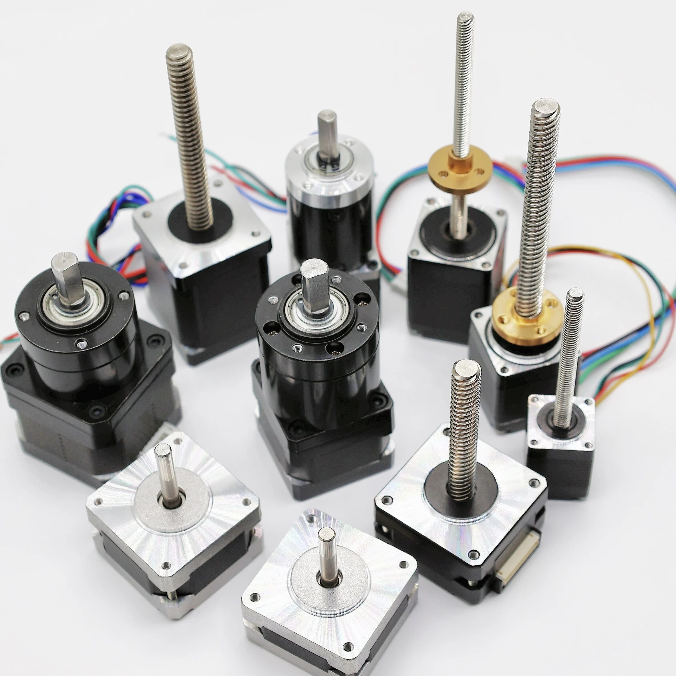
محرك Stepper هو محرك عديم الفُرش يدور على شكل خطوات منفصلة ودقيقة. ويُستخدم عندما تكون الحركة المتحكم بها والقابلة للتكرار مطلوبة.
تنتشر محركات Stepper في الطابعات ثلاثية الأبعاد، وآلات CNC، والروبوتات، والـ Plotters، وأنظمة تحديد الموضع.
ما هو محرك Stepper؟
محرك Stepper هو نوع من محركات DC عديمة الفُرش يمكن التحكم في موضعه بدقة حتى دون استخدام تغذية راجعة.
يعتمد مبدأ عمله على المجالات المغناطيسية، ويتكون أساسًا من جزأين: Stator وRotor. ويكون Rotor غالبًا مغناطيسًا دائمًا، بينما تحيط به ملفات موجودة على Stator.
المكونات الرئيسية لمحرك Stepper: Stator وRotor.
كيف يعمل محرك Stepper؟
عند تمرير التيار في الملفات، تتولد مجالات مغناطيسية في Stator تقوم بجذب Rotor أو دفعه. ومن خلال تنشيط الملفات بالتتابع وبترتيب محدد، يمكن الحصول على حركة مستمرة على شكل خطوات، كما يمكن إيقاف Rotor عند موضع معين.
مبدأ عمل محرك Stepper
ولهذا سُمّي Stepper، لأنه يتحرك على شكل خطوات منفصلة.
وكلما زاد عدد الأقطاب المغناطيسية في Rotor، زاد عدد المواضع الممكنة للتوقف، وبالتالي ترتفع دقة الحركة أو دقة تحديد الموضع. ويُعد هذا شرحًا مبسطًا لمبدأ العمل.

لماذا نحتاج إلى درايفر لمحرك Stepper؟
لا ينبغي لـ Arduino قيادة ملفات محرك Stepper مباشرةً، لأن المحرك يحتاج إلى تيار وطريقة تشغيل دقيقة للملفات. لذلك يُستخدم درايفر Stepper للتحكم في تيار المحرك وتنشيط الملفات بالتسلسل الصحيح.
Arduino → Stepper Driver → Stepper Motor
يمكن أن يوفر الدرايفر وظائف مهمة مثل:
- التحكم في الاتجاه.
- التحكم في الخطوات.
- تحديد التيار.
- Microstepping.
الاستخدامات الشائعة لمحرك Stepper
- الطابعات ثلاثية الأبعاد.
- آلات CNC.
- الروبوتات.
- أجهزة النقش بالليزر.
- Plotters.
- منصات تحريك الكاميرات.
- الآلات الآلية.
- أنظمة تحديد الموضع بدقة.
أمثلة على درايفرات محركات Stepper
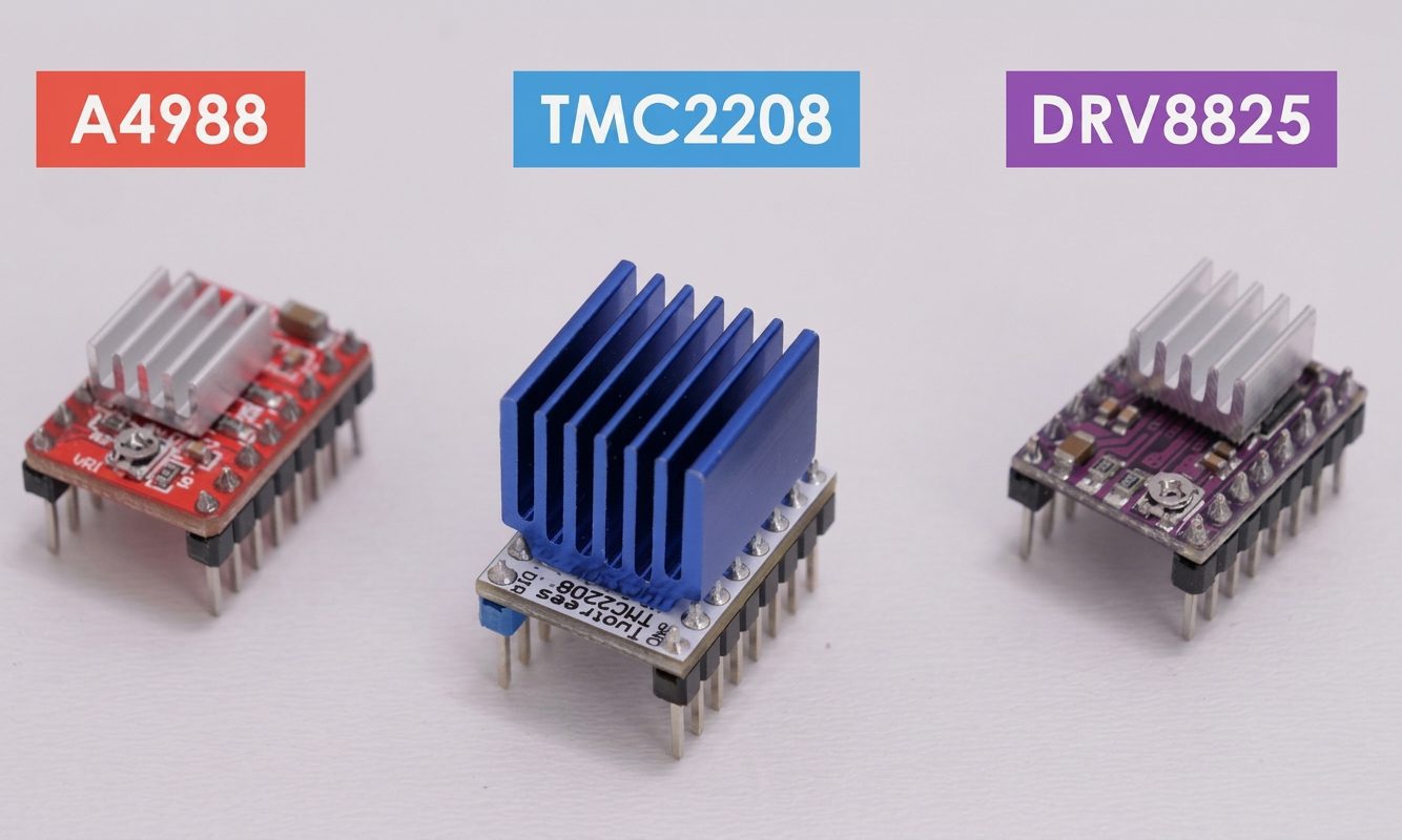
درايفر محرك Stepper من نوع A4988
يُعد A4988 من الدرايفرات الشائعة للتحكم في محركات NEMA 17 باستخدام Arduino.
أهم إشارتَي تحكم هما:
| الطرف | الوظيفة |
|---|---|
| STEP | يحرك المحرك خطوة واحدة مع كل نبضة. |
| DIR | يحدد اتجاه الدوران. |
يحصل المحرك على طاقته من مدخل طاقة المحرك في الدرايفر، وليس مباشرةً من Arduino.
توصيل Arduino مع درايفر A4988
يمكن استخدام التوصيل التالي:
| Arduino | A4988 |
|---|---|
| 5V | VDD. |
| GND | GND. |
| Digital Pin 2 | STEP. |
| Digital Pin 3 | DIR. |
وصل ملفي المحرك بالطرفين:
1A, 1B, 2A, 2B
استخدم مصدر طاقة خارجيًا مناسبًا للمحرك من خلال VMOT وGND.
مهم: يجب تحديد زوجَي ملفات المحرك بشكل صحيح، كما يجب التأكد من وجود GND مشترك بين Arduino والدرايفر.
طاقة المحرك وتحديد التيار
يجب أن يتوافق مصدر طاقة المحرك مع متطلبات المحرك والدرايفر.
يجب ضبط Current Limit في A4988 بما يتناسب مع التيار المقنن للمحرك. ضبطه على قيمة مرتفعة جدًا قد يسبب ارتفاع الحرارة، بينما ضبطه على قيمة منخفضة جدًا قد يقلل العزم المتاح.
ويُفضل وضع مكثف مناسب بالقرب من توصيلات طاقة المحرك في الدرايفر للمساعدة في تقليل تقلبات الجهد.
Microstepping
يدعم A4988 تقنية Microstepping التي تقسم الخطوة الكاملة إلى عدد أكبر من الخطوات الأصغر.
بالنسبة لمحرك بقدرة 200 خطوة لكل دورة:
| الوضع | الخطوات لكل دورة |
|---|---|
| Full Step | 200. |
| 1/2 Step | 400. |
| 1/4 Step | 800. |
| 1/8 Step | 1600. |
| 1/16 Step | 3200. |
يمكن أن توفر Microstepping حركة أكثر سلاسة وأقل ضوضاء، لكن زيادة عدد الخطوات المطلوبة لا تعني بالضرورة زيادة مماثلة في الدقة المطلقة لتحديد الموضع.
التحكم في المحرك باستخدام Arduino
يتحكم Arduino في A4988 باستخدام إشارتَي STEP وDIR.
- DIR يحدد اتجاه الدوران.
- STEP يحدد عدد الخطوات التي يتحركها المحرك.
- الفاصل الزمني بين نبضات STEP يحدد سرعة الحركة.
مثال بسيط:
const int stepPin = 2;
const int dirPin = 3;

void setup()
{
  pinMode(stepPin, OUTPUT);
  pinMode(dirPin, OUTPUT);
}

void loop()
{
  digitalWrite(dirPin, HIGH);

  for (int i = 0; i < 200; i++)
  {
    digitalWrite(stepPin, HIGH);
    delayMicroseconds(500);
    digitalWrite(stepPin, LOW);
    delayMicroseconds(500);
  }

  delay(1000);

  digitalWrite(dirPin, LOW);

  for (int i = 0; i < 200; i++)
  {
    digitalWrite(stepPin, HIGH);
    delayMicroseconds(500);
    digitalWrite(stepPin, LOW);
    delayMicroseconds(500);
  }

  delay(1000);
}
في محرك نموذجي بواقع 200 خطوة وفي وضع Full Step، تؤدي 200 نبضة تقريبًا إلى دورة واحدة.
التحكم في السرعة والاتجاه
الاتجاه
يتغير اتجاه المحرك بتغيير حالة طرف DIR.
digitalWrite(dirPin, HIGH);أو:
digitalWrite(dirPin, LOW);السرعة
تعتمد سرعة محرك Stepper على تردد نبضات STEP.
فواصل نبضات أقصر → سرعة أعلى.
فواصل نبضات أطول → سرعة أقل.
ولا يُنصح عادةً ببدء محرك Stepper مباشرةً بسرعة عالية جدًا، لأن التسارع الكبير قد يؤدي إلى فقدان خطوات.
استخدام مكتبة AccelStepper
في المشاريع المتقدمة يمكن أن تسهل مكتبة AccelStepper التحكم في محرك Stepper.
وتدعم وظائف مثل:
- التحكم في السرعة.
- التسارع.
- التباطؤ.
- التحكم في الموضع.
- التحكم في عدة محركات Stepper.
وتفيد بشكل خاص في الروبوتات وآلات CNC وأنظمة تحديد الموضع الآلية.
المشكلات الشائعة والاحتياطات المهمة
المحرك لا يدور
تحقق من توصيلات ملفات المحرك، ومصدر الطاقة، وإشارات STEP وDIR، وGND المشترك، وإعدادات الدرايفر.
المحرك يهتز لكنه لا يدور
قد تكون ملفات المحرك موصلة بطريقة غير صحيحة. تحقق من زوجَي الملفات.
ارتفاع حرارة المحرك
تحقق من إعداد Current Limit في A4988 وتأكد من ملاءمته للمحرك.
المحرك يفقد خطوات
قلل السرعة أو التسارع، وتحقق من مصدر طاقة المحرك وإعداد التيار والحمل الميكانيكي.
أي محرك تختار؟
يعتمد اختيار المحرك المناسب على طبيعة المهمة المطلوبة في المشروع.
| المحرك | الميزة الرئيسية | الاستخدام النموذجي |
|---|---|---|
| Servo | سهولة التحكم في الموضع. | ذراع روبوتية. |
| Stepper | حركة تدريجية يمكن التحكم فيها. | CNC / طابعة ثلاثية الأبعاد. |
| DC | دوران مستمر بسيط. | سيارة روبوتية. |
اختر Servo عندما:
تحتاج إلى تحريك جزء ميكانيكي إلى زاوية محددة ولا تحتاج إلى دوران مستمر.
اختر Stepper عندما:
تحتاج إلى دوران تدريجي مضبوط وحركة قابلة للتكرار.
اختر DC عندما:
تحتاج إلى دوران مستمر، مثل تشغيل عجلة أو مروحة أو مضخة.
الخاتمة
إن توصيل محرك مع Arduino لا يقتصر على توصيل سلكين بمنفذ رقمي. يوفر Arduino إشارات التحكم، بينما تتولى دائرة القيادة أو الدرايفر المناسب التعامل مع القدرة الكهربائية المطلوبة لتشغيل المحرك.
الأنظمة الأساسية للأنواع الثلاثة هي:
Servo Motor : Arduino → Control Signal → Servo Motor
Stepper Motor : Arduino → Stepper Driver → Stepper Motor
DC Motor : Arduino → Motor Driver → DC Motor
بعد اختيار الدرايفر ومصدر الطاقة والتوصيلات المناسبة، يستطيع Arduino توفير تحكم دقيق في موضع المحرك وسرعته واتجاهه، مما يجعل المحركات عنصرًا أساسيًا في الروبوتات والأتمتة والعديد من مشاريع Arduino.
الخلاصة: محرك Servo مع Arduino
يوفر محرك Servo القياسي طريقة سهلة للتحكم في الموضع الزاوي باستخدام Arduino. ويحتوي عادةً على ثلاثة توصيلات: VCC وGND وSignal.
تجعل مكتبة Servo عملية التحكم سهلة من خلال دوال مثل attach() وwrite(). وبعد توصيل Servo وإضافة المكتبة، يستطيع Arduino إرسال زوايا مختلفة إلى المحرك.
في المشاريع البسيطة يمكن التحكم في إشارة Servo من Arduino، لكن يجب الانتباه إلى متطلبات الطاقة. أما عند استخدام Servo عالي العزم أو عدة محركات، فيُفضل استخدام مصدر طاقة خارجي مناسب مع توصيل أرضيه بـ GND الخاص بـ Arduino.
تسلسل التحكم الأساسي هو:
توصيل Servo → إضافة مكتبة Servo → توصيل منفذ الإشارة → تحديد الزاوية → رفع البرنامج → مراقبة الحركة.
الخلاصة: محرك DC مع Arduino
يمكن لـ Arduino التحكم في سرعة واتجاه محرك DC، لكن يجب تشغيل المحرك من خلال درايفر مناسب بدلًا من توصيله مباشرةً بمنفذ Arduino.
يوفر L298N حلًا بسيطًا للتحكم في محرك DC واحد أو محركين. ويتولى ENA التحكم في السرعة باستخدام PWM، بينما يتحكم IN1 وIN2 في الاتجاه.
النظام الأساسي هو:
Arduino → L298N Motor Driver → DC Motor
مع استخدام مصدر طاقة خارجي مناسب للمحرك.
ومن خلال الجمع بين PWM للتحكم في السرعة وH-Bridge للتحكم في الاتجاه، يمكن لـ Arduino تسريع المحرك وإبطاؤه وعكس اتجاهه وإيقافه بطريقة منظمة.
الخلاصة: محرك Stepper مع Arduino
يوفر محرك Stepper حركة دقيقة ومنظمة من خلال الدوران على شكل خطوات منفصلة. ويمكن لـ Arduino التحكم فيه باستخدام درايفر مخصص مثل A4988.
نظام التحكم الأساسي هو:
Arduino → إشارات STEP/DIR → درايفر A4988 → Stepper Motor
تتحكم إشارة STEP في الحركة، بينما تحدد DIR الاتجاه. وتوفر Microstepping حركة أكثر سلاسة، كما أن ضبط حد التيار بشكل صحيح ضروري للتشغيل الآمن والموثوق.
وفي التطبيقات المتقدمة يمكن لمكتبات مثل AccelStepper توفير التحكم في السرعة والتسارع والتباطؤ والموضع.


Leave a comment
You must be logged in to post a comment.