


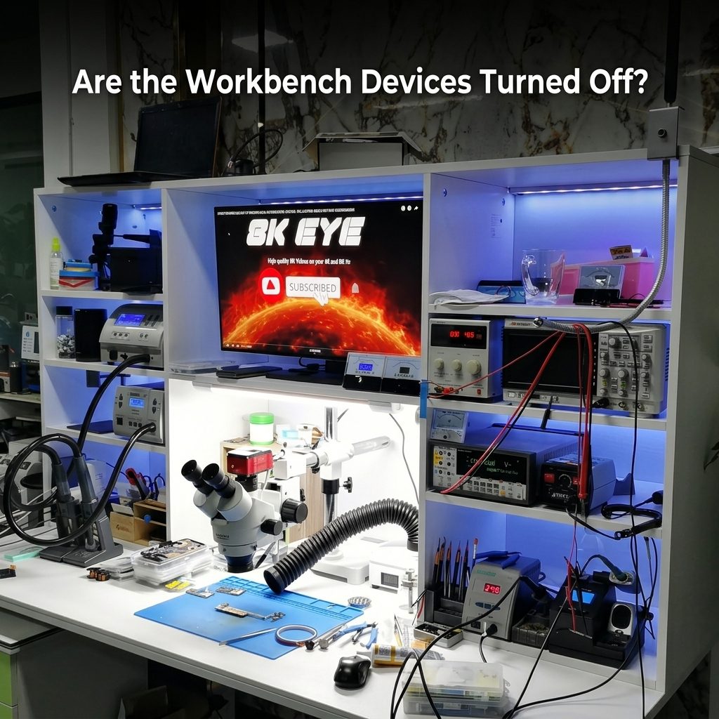
Are the Workbench Devices Turned Off?
Contents List
- Introduction to the Project
- What Is the Project?
- Project Components and Model Numbers
- Brief Overview of Each Circuit Component
- Workbench Loads to Be Monitored
- Exact Loads to Be Connected to the Project Circuit
- Detailed Circuit Schematic and Interconnections
- How the Project Measures Current
- How the Project Determines Whether a Device Is OFF
- OFF, Standby, and ON Detection
- Suggested Current Thresholds
- Calibration of the Current Sensors
- Software Platform
- Displaying the Workbench Status
- Monitoring the Workbench Through Wi-Fi
- Understanding the Measurements
- Electrical Safety Considerations
- Possible Project Improvements
- Frequently Asked Questions
- Conclusion
Reading Time is 20 minute
1. Introduction
An electronics workbench can contain several devices that are used throughout the day, including soldering stations, bench power supplies, monitors, chargers, development boards, test equipment, computers, and other electronic tools.
At the end of a work session, it is common to switch these devices off and assume that they are no longer consuming electricity.
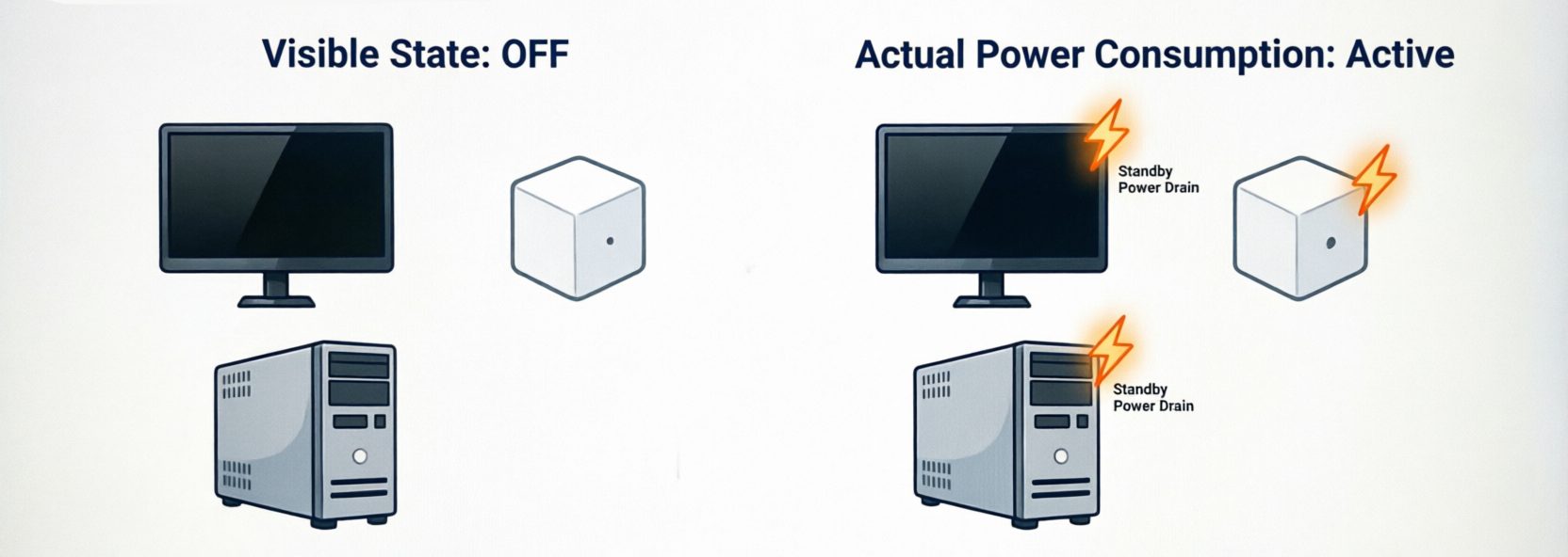
However, switching a device off does not always mean that its electrical consumption has reached zero.
Some electronic equipment can continue to draw a small amount of current while connected to the electrical supply. This may happen because internal circuits remain powered for functions such as status indicators, memory retention, network connectivity, remote control, or quick startup.
This project explores a practical question:
Are the devices on an electronics workbench really turned off, or are some of them still consuming electricity?
To answer this question, we can build a 10-channel workbench current-monitoring system using an ESP32, multiple ADS1115 analog-to-digital converters, and ten non-invasive SCT-013 current transformers.
The system measures the current associated with each connected load and uses calibrated thresholds to classify each device as OFF, STANDBY, or ON.
The project is useful for beginners because it introduces practical concepts such as current sensing, analog-to-digital conversion, RMS measurement, microcontrollers, I²C communication, and threshold-based device detection. It can also be expanded by hobbyists and engineers with Wi-Fi monitoring, data logging, graphs, and additional measurement capabilities.
2. What Is the Project?
The project is a 10-channel workbench device current-monitoring system based on a D1 Mini ESP32 development board.
Each of the ten workbench loads is monitored by its own SCT-013 100A/1V split-core current transformer. The sensors provide an isolated, non-invasive method of sensing the AC current flowing to the monitored equipment.
Because the ESP32 does not directly provide ten suitable external analog measurement channels for this design, three ADS1115 16-bit, 4-channel ADC modules are used to acquire the sensor signals.
The basic architecture is:
10 × SCT-013 100A/1V → 3 × ADS1115 → D1 Mini ESP32 → SSD1306 OLED
The ESP32 processes the sampled current signals, calculates RMS current, and compares the measured values with calibrated thresholds.
The system can then indicate:
- OFF — current is below the OFF threshold.
- STANDBY — current is present but below the normal operating threshold.
- ON — current reaches or exceeds the ON threshold.
The first version is designed as a current-monitoring and device-state detection system, not as a precision energy meter.
3. Project Components and Model Numbers
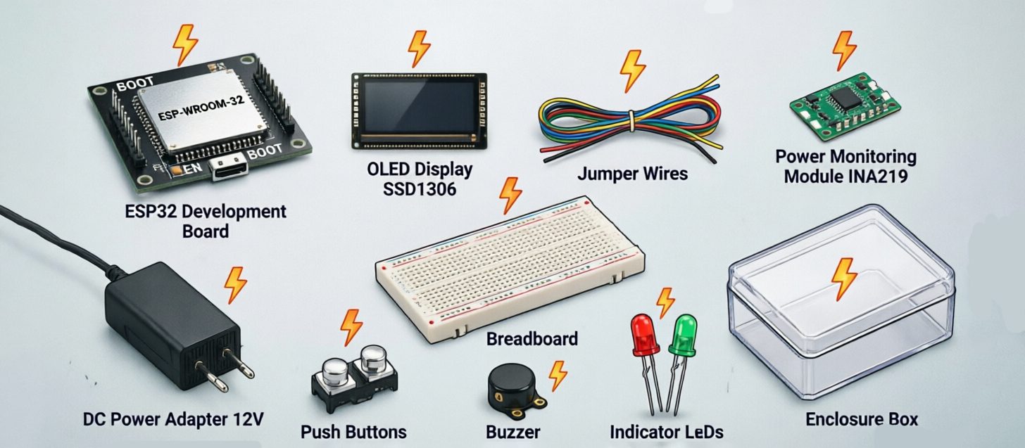
The following component list is based on the revised Makers Electronics parts selected for this project.
| Component | Recommended Makers Product / Specification | Quantity |
|---|---|---|
| Main controller | D1 Mini ESP32 WiFi + Bluetooth Development Board | 1 |
| ADC | ADS1115 16-Bit ADC 4-Channel with Programmable Gain Amplifier | 3 |
| AC current sensor | SCT-013 100A/1V Split-Core Current Transformer | 10 |
| OLED display | OLED Display I²C 4 Pin 0.96″, 128×64 | 1 |
| Bias resistors | 10 kΩ, 0.25 W through-hole resistors | 20+ |
| ADC input resistors | 100 kΩ through-hole resistors | 10 |
| Coupling capacitors | 1 µF 100Vcapacitors | 10 |
| Decoupling capacitors | 100 nF 50V ceramic capacitors | As required |
| Supply capacitors | 10 µF 400V capacitors | As required |
| DC power supply | 5V 700 mA / 3W AC/DC power-supply module | 1 |
| Terminal connectors | KF128/KF129 terminal blocks | As required |
| Jumper wires | 20 cm / 30 cm jumper wires | As required |
| Prototype board | 830-point breadboard or suitable Vero board | 1 |
| Enclosure | Black Plastic Project Box 75 × 55 × 30 mm | 1 |
The component selection has been changed from the earlier design so that the project is based on the new Makers Electronics component list.
Important: The current sensor used in this revised design is the SCT-013 100A/1V, not the previously specified SCT-013-010. Therefore, the current-scaling and calibration must be based on the actual 100A/1V sensor.
4. Brief Overview of Each Circuit Component
D1 Mini ESP32 WiFi + Bluetooth Development Board
The D1 Mini ESP32 is the main controller of the project.
It receives the digitized current measurements from the ADS1115 modules, processes the samples, calculates RMS current, determines the operating state of each load, and controls the OLED display.
Its Wi-Fi capability also provides a foundation for adding a browser-based monitoring dashboard in a future version.
ADS1115 16-Bit ADC
The ADS1115 is a 16-bit, four-channel analog-to-digital converter with a programmable gain amplifier.
Each module provides four analog input channels. Three modules therefore provide twelve available channels, which is enough for the ten current sensors used in this project.
The ADS1115 modules communicate with the ESP32 through the I²C interface.
SCT-013 100A/1V Current Transformer
The SCT-013 100A/1V is a split-core AC current transformer.
It can be clipped around a single current-carrying conductor without making a direct electrical connection to that conductor.
For this project, one SCT-013 sensor is assigned to each workbench load.
Because this sensor is rated for 100 A input and 1 V output, the signal conversion in the software must be based on this sensor’s actual characteristics and verified through calibration.
0.96-Inch SSD1306 OLED Display
The 128×64 I²C OLED provides a compact visual interface for the project.
It can display the name of each monitored device, its measured current, and its detected operating state.
10 kΩ Resistors
The 10 kΩ resistors are used to create the reference/bias network required to shift the AC sensor signal into a voltage range suitable for the ADC.
Two matched 10 kΩ resistors can be used to create a nominal midpoint reference from the 3.3 V logic supply.
100 kΩ Resistors
The 100 kΩ resistors provide the required input biasing for the AC-coupled sensor signals.
1 µF Capacitors
The 1 µF capacitors are used as AC-coupling capacitors between the current-transformer outputs and the ADC input stages.
100 nF Ceramic Capacitors
These capacitors are used for local high-frequency supply decoupling around the electronic modules.
10 µF Capacitors
The 10 µF capacitors provide additional local supply filtering and help reduce supply-voltage fluctuations.
5 V AC/DC Power-Supply Module
The 5 V power-supply module provides the low-voltage DC supply required by the electronics.
The supply must be installed safely because the input side is connected to mains voltage.
KF128/KF129 Terminal Blocks
Terminal blocks provide convenient and secure connections for the low-voltage wiring and sensor connections.
Jumper Wires
Jumper wires are useful during prototyping and for connecting the ESP32, ADS1115 modules, OLED, and other low-voltage components.
Prototype Board
An 830-point breadboard can be used while developing and testing the low-voltage circuit. A more permanent version can be transferred to a suitable Vero board or custom PCB.
Project Enclosure
The plastic project box provides mechanical protection for the low-voltage electronics.
The enclosure size may need to be increased if the final assembly includes additional terminals, wiring, power-supply hardware, or mains-side components.
5. Workbench Loads to Be Monitored
The project is designed to monitor ten common electronics-workbench loads:
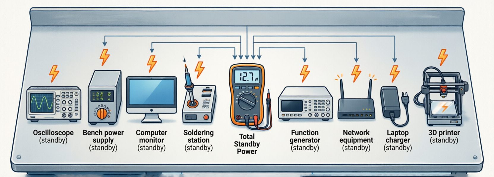
- Bench Power Supply
- Soldering Station
- Computer Monitor
- USB Charger
- Development Board Power Supply
- Oscilloscope
- Function Generator
- 3D Printer
- Network Equipment
- Laptop Charger
The objective is to monitor each load independently rather than measuring the combined current of the entire workbench.
6. Exact Loads to Be Connected to the Project Circuit
Each load receives its own current sensor.
| Channel | Monitored Load | Current Sensor |
|---|---|---|
| CH1 | Bench Power Supply | SCT-013 100A/1V #1 |
| CH2 | Soldering Station | SCT-013 100A/1V #2 |
| CH3 | Computer Monitor | SCT-013 100A/1V #3 |
| CH4 | USB Charger | SCT-013 100A/1V #4 |
| CH5 | Development Board Power Supply | SCT-013 100A/1V #5 |
| CH6 | Oscilloscope | SCT-013 100A/1V #6 |
| CH7 | Function Generator | SCT-013 100A/1V #7 |
| CH8 | 3D Printer | SCT-013 100A/1V #8 |
| CH9 | Network Equipment | SCT-013 100A/1V #9 |
| CH10 | Laptop Charger | SCT-013 100A/1V #10 |
Each SCT-013 should monitor one load only.
This allows the ESP32 to determine which individual device is consuming current.
7. Detailed Circuit Schematic and Interconnections
The main circuit can be divided into four functional sections:
Current Sensors → Signal Conditioning → ADS1115 ADCs → ESP32/OLED
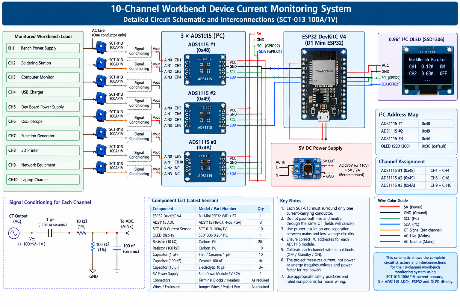
The ten SCT-013 sensors are distributed across three ADS1115 modules.
ADS1115 Channel Assignment
| ADC Module | ADC Channel | Workbench Load |
|---|---|---|
| ADS1115 #1 | A0 | Bench Power Supply |
| ADS1115 #1 | A1 | Soldering Station |
| ADS1115 #1 | A2 | Computer Monitor |
| ADS1115 #1 | A3 | USB Charger |
| ADS1115 #2 | A0 | Development Board Power Supply |
| ADS1115 #2 | A1 | Oscilloscope |
| ADS1115 #2 | A2 | Function Generator |
| ADS1115 #2 | A3 | 3D Printer |
| ADS1115 #3 | A0 | Network Equipment |
| ADS1115 #3 | A1 | Laptop Charger |
| ADS1115 #3 | A2 | Spare |
| ADS1115 #3 | A3 | Spare |
I²C Connections
The three ADS1115 modules and the OLED share the ESP32’s I²C bus.
Example addresses are:
- ADS1115 #1 →
0x48 - ADS1115 #2 →
0x49 - ADS1115 #3 →
0x4A - OLED →
0x3C
The exact address configuration depends on how the ADS1115 address pins are connected.
Sensor Signal Connection
Each SCT-013 output is connected to an AC-coupling and bias network before reaching an ADS1115 analog input.
The general signal path is:
SCT-013 → 1 µF coupling capacitor → ADC input → 100 kΩ bias resistor → VBIAS
A midpoint bias voltage is created from the low-voltage supply using matched resistors so that the AC waveform is centered within the ADC’s positive input range.
Important Current-Transformer Installation
The SCT-013 must be placed around one current-carrying conductor only.
Do not pass both live and neutral conductors through the same current transformer because their magnetic fields can substantially cancel, resulting in an incorrect or very small measurement.
The mains-side installation must remain physically separated from the low-voltage electronics.
8. How the Project Measures Current
The SCT-013 100A/1V produces an AC voltage corresponding to the current flowing through the monitored conductor.
The ADS1115 samples this waveform and sends the digital measurements to the ESP32 through I²C.
The ESP32 can calculate RMS current using:
I<sub>RMS</sub> = √[(I₁² + I₂² + … + I<sub>N</sub>²) / N]
RMS current provides a useful representation of the magnitude of an AC current waveform.
However, the exact conversion from measured ADC voltage to current must be calibrated for the SCT-013 100A/1V used in this project.
The software should therefore not blindly reuse the conversion factor from the previous SCT-013-010 design.
9. How the Project Determines Whether a Device Is OFF
The project does not determine the state of a device by checking its physical power switch.
Instead, it measures the current flowing to the device.
If the measured current remains below the calibrated OFF threshold, the system classifies the device as OFF.
If a small current remains after the device has apparently been switched off, the system can classify the device as STANDBY.
This makes the system useful for identifying equipment that continues to consume electricity when it is not actively being used.
10. OFF, Standby, and ON Detection
The system uses three states:
| State | Meaning |
|---|---|
| OFF | Measured current is below the OFF threshold |
| STANDBY | Current is above the OFF threshold but below the ON threshold |
| ON | Current reaches or exceeds the ON threshold |
This three-state approach is more informative than a simple ON/OFF indicator.
It is especially useful for equipment such as monitors, chargers, networking equipment, and laboratory instruments that may continue consuming current after their primary function has been disabled.
11. Suggested Current Thresholds
The following values can be used as initial example thresholds for software development and testing:
| Load | OFF → Standby | Standby → ON |
|---|---|---|
| Bench Power Supply | < 0.03 A | ≥ 0.15 A |
| Soldering Station | < 0.04 A | ≥ 0.20 A |
| Computer Monitor | < 0.03 A | ≥ 0.08 A |
| USB Charger | < 0.02 A | ≥ 0.05 A |
| Development Board Power Supply | < 0.02 A | ≥ 0.06 A |
| Oscilloscope | < 0.04 A | ≥ 0.15 A |
| Function Generator | < 0.03 A | ≥ 0.10 A |
| 3D Printer | < 0.04 A | ≥ 0.30 A |
| Network Equipment | < 0.05 A | ≥ 0.12 A |
| Laptop Charger | < 0.03 A | ≥ 0.10 A |
These are suggested starting values, not measured specifications for particular commercial devices.
The actual thresholds should be determined experimentally after the equipment is connected.
Because the revised design uses the 100A/1V SCT-013, the low-current measurement resolution should also be evaluated carefully. Very small standby currents may be close to the practical noise floor of the complete sensor/ADC circuit.
12. Calibration of the Current Sensors
Calibration is particularly important in this project because the system is intended to distinguish relatively small differences between OFF, standby, and normal operation.
For each load:
- Connect the device to its assigned monitoring channel.
- Measure the current while the device is OFF.
- Measure the current while the device is in standby, if applicable.
- Measure the current during normal operation.
- Record the measured values.
- Compare the measured values with the initial thresholds.
- Adjust the OFF and ON thresholds as necessary.
- Repeat the process for all ten loads.
For example, if a monitor measures approximately 0.01 A when OFF, 0.03 A in standby, and 0.12 A during operation, the thresholds can be selected between those measured states.
The calibration values should be stored in the C++ program or, in a future version, saved in non-volatile memory so that they can be changed without recompiling the program.
13. Software Platform
The recommended software platform is:
D1 Mini ESP32 + Arduino IDE + ESP32 Arduino Core + C/C++
The program performs the following main tasks:
- Initializes the ESP32.
- Initializes the three ADS1115 modules.
- Initializes the OLED display.
- Reads the ten current channels.
- Calculates RMS current.
- Converts the sensor signal into an estimated current value.
- Compares the current with the calibrated thresholds.
- Determines whether each load is OFF, STANDBY, or ON.
- Displays the results on the OLED.
- Sends measurement information to the Serial Monitor.
- Provides a foundation for future Wi-Fi monitoring.
14. Displaying the Workbench Status
The 0.96-inch 128×64 OLED has limited display space.
Displaying ten devices with their names, current values, and operating states simultaneously would make the text difficult to read.
Therefore, the project can use multiple pages.
For example:
Page 1
- Bench Power Supply
- Soldering Station
- Computer Monitor
- USB Charger
- Development Board Supply
Page 2
- Oscilloscope
- Function Generator
- 3D Printer
- Network Equipment
- Laptop Charger
Each device can be displayed with its approximate current and state.
Example:
Monitor
0.03 A — STANDBY
This makes the status easy to understand at a glance.
15. Monitoring the Workbench Through Wi-Fi
The D1 Mini ESP32 includes Wi-Fi capability, allowing a future version of the project to provide a web-based dashboard.
A browser-based interface could display:
- Device name
- Measured current
- OFF / STANDBY / ON status
- Number of active devices
- Number of devices in standby
- Current readings
- Historical measurements
- Possible unnecessary consumption
This would transform the project from a simple local monitor into a smart workbench monitoring system.
16. Understanding the Measurements
It is important to distinguish between current, power, and energy.
Current
Current is the quantity directly measured by the SCT-013 current transformer.
It tells us how much electrical current is flowing through the monitored conductor.
Power
Electrical power depends on both voltage and current. For AC loads, the phase relationship and waveform characteristics can also affect real power.
Therefore, current alone cannot provide an accurate measurement of real power for every type of load.
Energy
Energy is the amount of electrical work consumed over time, normally expressed in watt-hours or kilowatt-hours.
Accurate energy measurement requires appropriate voltage and power measurements and integration over time.
Therefore, this project should be described as a:
10-channel AC current-monitoring and device-state detection system
rather than a precision energy meter.
17. Electrical Safety Considerations
This project monitors equipment connected to mains electricity, so safety must be treated as a fundamental part of the design.
The SCT-013 provides non-invasive current sensing, but the monitored conductors and mains connections remain potentially dangerous.
Follow these precautions:
- Use appropriately rated mains cables and connectors.
- Keep mains wiring physically separated from the low-voltage electronics.
- Use an appropriate insulated enclosure.
- Provide proper strain relief.
- Use correctly rated terminal blocks.
- Never work on energized mains wiring.
- Never expose mains conductors inside an accessible enclosure.
- Place the SCT-013 around only the intended conductor.
- Do not exceed the sensor’s specified operating conditions.
- Ensure the 5 V power-supply module is installed according to its electrical requirements.
- Have mains-side wiring performed or checked by a suitably qualified person where required.
The initial version of the project should remain monitor-only. It should not directly switch mains loads.
18. Possible Project Improvements
Once the basic monitoring system is working, several improvements can be added.
Wi-Fi Dashboard
Create a web interface that displays all ten loads in real time.
Data Logging
Store current measurements so the user can review equipment usage over hours, days, or weeks.
Graphs
Display current trends for individual devices.
Notifications
The ESP32 could notify the user when equipment remains in standby for a specified period.
Improved Calibration
Add an interface that allows the user to change each device’s thresholds without modifying the source code.
More Monitoring Channels
The two unused ADS1115 channels can provide additional flexibility for future expansion.
Real Power Measurement
Additional voltage and phase measurement circuitry can be added if the project is later developed into a real-power or energy-monitoring system.
Automatic Load Control
A future version could use appropriately rated, isolated switching hardware to control selected loads. Such an upgrade would require a separate safety-focused design for mains switching.
19. Frequently Asked Questions
Can the project detect whether a device is completely turned off?
Yes, but it detects the device state by measuring its AC current rather than directly detecting the position of the power switch.
If the measured current remains below the calibrated OFF threshold, the system classifies the device as OFF.
If the device continues to draw a small amount of current, it can instead be classified as STANDBY.
Why are three ADS1115 modules required?
Each ADS1115 provides four analog input channels.
The project has ten independent current sensors, so three ADS1115 modules provide twelve available inputs.
This gives the project enough channels for all ten loads while leaving two channels available for possible future expansion.
Why is the SCT-013 100A/1V used in this revised project?
The SCT-013 100A/1V is the current-transformer model selected from the revised Makers Electronics component list.
It provides a voltage output corresponding to the AC current flowing through the monitored conductor and allows non-invasive current measurement.
The software and calibration must be designed specifically around this sensor.
Can one current sensor monitor multiple devices?
Not if the system needs to determine the state of each device individually.
Each monitored load should have its own SCT-013.
If several devices share one sensor, the sensor measures their combined current and the system cannot determine which device is responsible for the measured current.
Why must the SCT-013 surround only one conductor?
The current transformer responds to the magnetic field produced by current flowing through a conductor.
If both live and neutral conductors are passed through the same CT, their magnetic fields can substantially cancel because the currents flow in opposite directions.
The resulting measurement can therefore be very small or incorrect.
Can the project accurately measure the power consumed by each device?
Not with the current-monitoring hardware alone.
The SCT-013 measures current, but accurate real-power measurement also requires suitable voltage and phase information.
Therefore, this version of the project should be considered a current-monitoring and device-state detection system.
Can the OLED display all ten devices at once?
Technically, information can be compressed onto the display, but doing so would make the text difficult to read.
A better solution is to use two or more display pages, with approximately five devices per page.
Can the current thresholds be changed?
Yes.
The thresholds are software-defined and can be adjusted for each monitored device.
The example thresholds in this article are starting values only. The actual thresholds should be determined through calibration with the specific equipment being monitored.
Can the project work without Wi-Fi?
Yes.
The basic system can operate locally using the ESP32, ADS1115 modules, and OLED display.
Wi-Fi is an optional feature that can be added for remote monitoring, web dashboards, and data logging.
What happens if a device has an extremely low standby current?
Very low standby currents can be difficult to distinguish from sensor noise and measurement errors.
This is especially important when monitoring low-current electronic devices with a high-range 100A/1V current transformer.
For this reason, actual measurements should be taken during calibration before selecting the final thresholds.
Does the project measure every type of electrical load equally well?
Not necessarily.
Different devices can have different current waveforms, startup currents, standby behavior, and power factors.
The project is intended for typical electronics-workbench equipment, but every load should be tested and calibrated individually.
Can the project be expanded beyond ten devices?
Yes.
The three ADS1115 modules provide twelve analog channels, of which ten are currently used.
The remaining two channels can be used for additional measurements, subject to the limitations of the complete circuit and software.
Additional ADC modules can also be considered for a larger system.
Can the project automatically turn equipment off?
The basic project is monitor-only.
It detects and displays equipment status but does not disconnect the loads from mains power.
Automatic switching can be considered as a future enhancement using properly rated and isolated switching hardware with appropriate electrical-safety measures.
20. Conclusion
The Are the Workbench Devices Turned Off? project provides a practical way to monitor the current consumption of equipment commonly found on an electronics workbench.
Using ten SCT-013 100A/1V current transformers, three ADS1115 ADC modules, a D1 Mini ESP32, and a 0.96-inch OLED display, the system can monitor ten separate loads and classify them as OFF, STANDBY, or ON.
The revised component selection also makes the project easier to build around the components selected from Makers Electronics, including the controller, ADC modules, current sensors, display, passive components, connectors, wiring, power supply, prototype board, and enclosure.
More importantly, the project demonstrates several practical electronics concepts in one system, including AC current sensing, signal conditioning, analog-to-digital conversion, RMS calculations, I²C communication, embedded C/C++ programming, calibration, and device-state detection.
The system can begin as a simple local monitoring device and later be expanded with Wi-Fi, data logging, graphs, notifications, and more advanced electrical measurements.
With proper calibration and safe mains-side construction, it can become a useful tool for answering a simple but important workbench question.
هل أجهزة طاولة العمل مطفأة بالفعل؟
قائمة المحتويات
- مقدمة عن المشروع
- ما هو المشروع؟
- مكونات المشروع وأرقام الموديلات
- نبذة مختصرة عن كل مكوّن في الدائرة
- الأحمال الموجودة على طاولة العمل التي سيتم مراقبتها
- الأحمال المحددة التي سيتم توصيلها بدائرة المشروع
- المخطط التفصيلي للدائرة والتوصيلات البينية
- كيف يقيس المشروع التيار؟
- كيف يحدد المشروع ما إذا كان الجهاز في وضع الإيقاف؟
- تمييز حالات الإيقاف والاستعداد والتشغيل
- قيم التيار المقترحة للعتبات
- معايرة حساسات التيار
- منصة البرمجة
- عرض حالة طاولة العمل
- مراقبة طاولة العمل عبر Wi-Fi
- فهم القياسات
- اعتبارات السلامة الكهربائية
- التطويرات والتحسينات الممكنة للمشروع
- الأسئلة الشائعة
- الخلاصة
مدة القراءة حوالي : 20 دقيقة
1. مقدمة عن المشروع
قد تحتوي طاولة العمل الإلكترونية على العديد من الأجهزة التي تُستخدم على مدار اليوم، مثل محطات اللحام، ومصادر التغذية المختبرية، والشاشات، والشواحن، ولوحات التطوير، وأجهزة القياس والاختبار، وأجهزة الكمبيوتر، وغيرها من الأدوات الإلكترونية.
وفي نهاية جلسة العمل، من المعتاد إيقاف تشغيل هذه الأجهزة والافتراض بأنها لم تعد تستهلك أي كهرباء.
لكن إيقاف تشغيل الجهاز لا يعني بالضرورة أن استهلاكه الكهربائي أصبح صفراً.
فبعض الأجهزة الإلكترونية قد تستمر في سحب قدر صغير من التيار ما دامت متصلة بمصدر الكهرباء. وقد يحدث ذلك لأن بعض الدوائر الداخلية تظل في حالة تغذية لتنفيذ وظائف مثل مؤشرات الحالة، والاحتفاظ ببعض البيانات، والاتصال بالشبكة، والتحكم عن بُعد، أو تسريع بدء التشغيل.
ومن هنا يطرح هذا المشروع سؤالاً عملياً:
هل الأجهزة الموجودة على طاولة العمل الإلكترونية متوقفة فعلاً، أم أن بعضها ما زال يستهلك الكهرباء؟
للإجابة عن هذا السؤال، يمكن بناء نظام لمراقبة التيار في 10 قنوات مستقلة باستخدام وحدة ESP32، وعدة محولات تماثلية إلى رقمية ADS1115، وعشرة محولات تيار SCT-013 غير تلامسية.
يقيس النظام التيار المرتبط بكل حمل متصل، ثم يستخدم عتبات تمت معايرتها لتصنيف حالة كل جهاز إلى متوقف، أو في وضع الاستعداد، أو يعمل.
يُعد هذا المشروع مناسباً للمبتدئين لأنه يجمع بين مفاهيم عملية متعددة، مثل استشعار التيار، والتحويل من تماثلي إلى رقمي، وحساب قيمة RMS، واستخدام المتحكمات الدقيقة، والاتصال عبر I²C، واكتشاف حالة الجهاز اعتماداً على العتبات. كما يمكن للهواة والمهندسين تطويره بإضافة المراقبة عبر Wi-Fi، وتسجيل البيانات، وإنشاء الرسوم البيانية، وإضافة إمكانات قياس أخرى.
2. ما هو المشروع؟
المشروع عبارة عن نظام لمراقبة تيار عشرة أجهزة موجودة على طاولة العمل، ويعتمد على لوحة تطوير D1 Mini ESP32.
يتم مراقبة كل حمل من الأحمال العشرة بواسطة محول تيار مستقل من نوع SCT-013 100A/1V ذي القلب المنفصل. وتوفر هذه الحساسات وسيلة معزولة وغير تلامسية لقياس تيار التيار المتردد الذي يمر إلى الأجهزة المراد مراقبتها.
وبما أن ESP32 لا يوفر بشكل مباشر العدد المطلوب من قنوات القياس التماثلية الخارجية لهذا التصميم، يتم استخدام ثلاث وحدات ADS1115 بدقة 16 بت، وتحتوي كل وحدة على أربع قنوات، لقراءة إشارات الحساسات.
البنية الأساسية للنظام:
10 × SCT-013 100A/1V → 3 × ADS1115 → D1 Mini ESP32 → OLED 128×64
تعالج وحدة ESP32 الإشارات التي تم أخذ عينات منها، وتحسب قيمة التيار الفعالة RMS، ثم تقارن القياسات بالعتبات التي تمت معايرتها مسبقاً.
وبعد ذلك يستطيع النظام تحديد حالة كل جهاز على النحو التالي:
- متوقف (OFF): عندما يكون التيار أقل من عتبة الإيقاف.
- استعداد (STANDBY): عندما يوجد تيار، لكنه أقل من عتبة التشغيل الطبيعية.
- يعمل (ON): عندما يصل التيار إلى عتبة التشغيل أو يتجاوزها.
الإصدار الأول من المشروع مصمم ليكون نظاماً لمراقبة التيار وتحديد حالة الأجهزة، وليس عداداً دقيقاً للطاقة الكهربائية.
3. مكونات المشروع وأرقام الموديلات
تعتمد قائمة المكونات التالية على المكونات التي تم اختيارها من منتجات Makers Electronics لهذا المشروع.
| المكوّن | المنتج أو المواصفة المقترحة | الكمية |
|---|---|---|
| وحدة التحكم الرئيسية | D1 Mini ESP32 WiFi + Bluetooth Development Board | 1 |
| المحوّل التماثلي إلى رقمي ADC | ADS1115 16-Bit ADC 4-Channel with Programmable Gain Amplifier | 3 |
| حساس تيار متردد | SCT-013 100A/1V Split-Core Current Transformer | 10 |
| شاشة OLED | OLED Display I²C 4 Pin 0.96″، بدقة 128×64 | 1 |
| مقاومات انحياز | 10 kΩ، 0.25 W، مقاومات Through-Hole | 20 أو أكثر |
| مقاومات دخل ADC | 100 kΩ، مقاومات Through-Hole | 10 |
| مكثفات الربط | 1 µF 100V | 10 |
| مكثفات إزالة التشويش | 100 nF 50V، سيراميكية | حسب الحاجة |
| مكثفات تغذية | 10 µF 400V | حسب الحاجة |
| مصدر تغذية DC | 5V 700 mA / 3W، AC/DC Power Supply Module | 1 |
| وصلات طرفية | KF128/KF129 Terminal Blocks | حسب الحاجة |
| أسلاك توصيل | أسلاك Jumper Wires بطول 20 سم / 30 سم | حسب الحاجة |
| لوحة تجارب | 830-point Breadboard أو لوحة Vero مناسبة | 1 |
| صندوق المشروع | Black Plastic Project Box 75 × 55 × 30 mm | 1 |
تم تغيير مكونات المشروع مقارنة بالتصميم السابق بحيث يعتمد هذا الإصدار على قائمة المكونات الجديدة المختارة من Makers Electronics.
مهم: حساس التيار المستخدم في هذا التصميم المعدّل هو SCT-013 100A/1V وليس الحساس السابق SCT-013-010. لذلك يجب أن يعتمد تحويل التيار ومعايرته على خصائص حساس 100A/1V الفعلي المستخدم في الدائرة.
4. نبذة مختصرة عن كل مكوّن في الدائرة
D1 Mini ESP32 WiFi + Bluetooth Development Board
تُعد لوحة D1 Mini ESP32 وحدة التحكم الرئيسية في المشروع.
تستقبل اللوحة قياسات التيار الرقمية من وحدات ADS1115، وتعالج العينات، وتحسب قيمة RMS للتيار، وتحدد حالة كل حمل، كما تتحكم في شاشة OLED.
كما توفر خاصية Wi-Fi أساساً لإضافة لوحة مراقبة تعمل من خلال متصفح الويب في إصدار لاحق.
ADS1115 16-Bit ADC
وحدة ADS1115 عبارة عن محوّل تماثلي إلى رقمي بدقة 16 بت، وتحتوي على أربع قنوات إدخال مع مضخم كسب قابل للبرمجة.
توفر كل وحدة أربع قنوات تماثلية. لذلك فإن استخدام ثلاث وحدات يوفر اثنتي عشرة قناة، وهو عدد كافٍ لقراءة الحساسات العشرة المستخدمة في المشروع.
تتصل وحدات ADS1115 بوحدة ESP32 عبر واجهة الاتصال I²C.
SCT-013 100A/1V Current Transformer
حساس SCT-013 100A/1V عبارة عن محول تيار متردد ذو قلب منفصل.
يمكن تثبيته حول موصل واحد يحمل التيار من دون الحاجة إلى إجراء اتصال كهربائي مباشر بهذا الموصل.
في هذا المشروع، يتم تخصيص حساس SCT-013 واحد لكل حمل من الأحمال التي تتم مراقبتها.
وبما أن هذا الحساس مصمم لتيار دخل يصل إلى 100 A ويعطي خرجاً اسميّاً قدره 1 V، فيجب أن يعتمد تحويل الإشارة في البرنامج على خصائص الحساس الفعلي، مع التحقق من النتائج بواسطة المعايرة.
شاشة OLED بحجم 0.96 بوصة ودقة 128×64
توفر شاشة OLED ذات الاتصال عبر I²C واجهة عرض صغيرة ومناسبة للمشروع.
يمكنها عرض اسم الجهاز الذي تتم مراقبته، والتيار المقاس، والحالة التي تم اكتشافها.
مقاومات 10 kΩ
تستخدم مقاومات 10 kΩ لإنشاء شبكة الانحياز أو المرجع المطلوبة لتحريك إشارة الحساس إلى نطاق جهد مناسب لمدخل ADC.
ويمكن استخدام مقاومتين متساويتين بقيمة 10 kΩ لإنشاء جهد مرجعي متوسط اسمي من مصدر 3.3 V.
مقاومات 100 kΩ
تُستخدم مقاومات 100 kΩ لتوفير انحياز مناسب لمدخل ADC بعد تمرير إشارة الحساس عبر مكثف الربط.
مكثفات 1 µF
تستخدم مكثفات 1 µF لربط إشارة التيار المتردد بين خرج محول SCT-013 ومرحلة إدخال ADC، مع حجب المكوّن المستمر.
مكثفات السيراميك 100 nF
تستخدم هذه المكثفات لتقليل التشويش عالي التردد وتحسين إزالة الضوضاء من خطوط تغذية الوحدات الإلكترونية.
مكثفات 10 µF
توفر مكثفات 10 µF ترشيحاً إضافياً لخط التغذية وتساعد على تقليل التغيرات السريعة في جهد التغذية.
وحدة تغذية AC/DC بخرج 5 V
توفر وحدة التغذية بجهد 5 V مصدر التيار المستمر منخفض الجهد المطلوب لتشغيل الدائرة الإلكترونية.
يجب تركيب هذه الوحدة بطريقة آمنة لأن جانب دخلها متصل بجهد الشبكة الكهربائية.
وصلات KF128/KF129 الطرفية
تستخدم الوصلات الطرفية لتوفير نقاط توصيل منظمة وآمنة لأسلاك الجهد المنخفض وتوصيلات الحساسات.
أسلاك Jumper
تُستخدم أسلاك التوصيل أثناء مرحلة التجربة الأولية لربط ESP32 ووحدات ADS1115 وشاشة OLED وباقي المكونات منخفضة الجهد.
لوحة التجارب
يمكن استخدام لوحة تجارب 830 نقطة أثناء تطوير واختبار دائرة الجهد المنخفض. وبعد التأكد من عمل التصميم، يمكن نقله إلى لوحة Vero مناسبة أو إلى لوحة PCB مصممة خصيصاً للمشروع.
صندوق المشروع
يوفر الصندوق البلاستيكي حماية ميكانيكية للمكونات الإلكترونية منخفضة الجهد.
وقد تحتاج النسخة النهائية إلى صندوق أكبر إذا تضمنت مجموعة التوصيلات النهائية، أو الوصلات الطرفية، أو مكونات التغذية، أو أي مكونات مرتبطة بجانب التيار الكهربائي الرئيسي.
5. الأحمال الموجودة على طاولة العمل التي سيتم مراقبتها
صُمم المشروع لمراقبة عشرة أحمال شائعة يمكن وجودها على طاولة العمل الإلكترونية:
- مصدر تغذية مختبري
- محطة لحام
- شاشة كمبيوتر
- شاحن USB
- مصدر تغذية للوحة تطوير
- راسم ذبذبات Oscilloscope
- مولد إشارات Function Generator
- طابعة ثلاثية الأبعاد
- معدات شبكة
- شاحن كمبيوتر محمول
الهدف هو مراقبة كل حمل بشكل مستقل، بدلاً من قياس التيار الكلي لجميع الأجهزة الموجودة على طاولة العمل.
6. الأحمال المحددة التي سيتم توصيلها بدائرة المشروع
يُخصص حساس تيار مستقل لكل حمل.
| القناة | الحمل الذي تتم مراقبته | حساس التيار |
|---|---|---|
| CH1 | مصدر التغذية المختبري | SCT-013 100A/1V #1 |
| CH2 | محطة اللحام | SCT-013 100A/1V #2 |
| CH3 | شاشة الكمبيوتر | SCT-013 100A/1V #3 |
| CH4 | شاحن USB | SCT-013 100A/1V #4 |
| CH5 | مصدر تغذية لوحة التطوير | SCT-013 100A/1V #5 |
| CH6 | راسم الذبذبات | SCT-013 100A/1V #6 |
| CH7 | مولد الإشارات | SCT-013 100A/1V #7 |
| CH8 | الطابعة ثلاثية الأبعاد | SCT-013 100A/1V #8 |
| CH9 | معدات الشبكة | SCT-013 100A/1V #9 |
| CH10 | شاحن الكمبيوتر المحمول | SCT-013 100A/1V #10 |
يجب أن يراقب كل حساس SCT-013 حملاً واحداً فقط.
وبذلك تستطيع وحدة ESP32 تحديد أي جهاز من الأجهزة العشرة يستهلك التيار.
7. المخطط التفصيلي للدائرة والتوصيلات البينية
يمكن تقسيم الدائرة الرئيسية إلى أربع مراحل وظيفية:
حساسات التيار ← تهيئة الإشارة ← وحدات ADS1115 ← ESP32 / OLED
يتم توزيع حساسات SCT-013 العشرة على ثلاث وحدات ADS1115.
توزيع قنوات ADS1115
| وحدة ADC | قناة ADC | الحمل الموجود على طاولة العمل |
|---|---|---|
| ADS1115 #1 | A0 | مصدر التغذية المختبري |
| ADS1115 #1 | A1 | محطة اللحام |
| ADS1115 #1 | A2 | شاشة الكمبيوتر |
| ADS1115 #1 | A3 | شاحن USB |
| ADS1115 #2 | A0 | مصدر تغذية لوحة التطوير |
| ADS1115 #2 | A1 | راسم الذبذبات |
| ADS1115 #2 | A2 | مولد الإشارات |
| ADS1115 #2 | A3 | الطابعة ثلاثية الأبعاد |
| ADS1115 #3 | A0 | معدات الشبكة |
| ADS1115 #3 | A1 | شاحن الكمبيوتر المحمول |
| ADS1115 #3 | A2 | احتياطي |
| ADS1115 #3 | A3 | احتياطي |
توصيلات I²C
تشترك وحدات ADS1115 الثلاث وشاشة OLED في ناقل I²C نفسه مع وحدة ESP32.
عناوين I²C المستخدمة كمثال هي:
- ADS1115 #1 → 0x48
- ADS1115 #2 → 0x49
- ADS1115 #3 → 0x4A
- OLED → 0x3C
ويعتمد العنوان الفعلي لكل وحدة ADS1115 على طريقة توصيل طرف ADDR.
توصيل إشارة الحساس
يتم توصيل خرج كل SCT-013 بدائرة ربط وانحياز قبل وصول الإشارة إلى مدخل ADS1115 التماثلي.
مسار الإشارة العام:
SCT-013 → 1 µF coupling capacitor → ADC input → 100 kΩ bias resistor → VBIAS
يتم إنشاء جهد انحياز متوسط من مصدر الجهد منخفض المستوى باستخدام مقاومات متساوية، بحيث تتمركز إشارة التيار المتردد داخل نطاق جهد مناسب لمدخل ADC.
ملاحظة مهمة عند تركيب محول التيار
يجب وضع SCT-013 حول موصل واحد فقط يحمل التيار.
لا تمرر موصلي الخط الحي والمحايد معاً داخل محول التيار نفسه، لأن المجالين المغناطيسيين الناتجين عن التيارين قد يتلاشيان بدرجة كبيرة، مما يؤدي إلى قراءة صغيرة جداً أو غير صحيحة.
كما يجب إبقاء توصيلات التيار الكهربائي الرئيسي منفصلة فعلياً عن دوائر الجهد المنخفض.
8. كيف يقيس المشروع التيار؟
ينتج محول التيار SCT-013 100A/1V جهداً متردداً يتناسب مع التيار المار في الموصل الذي تتم مراقبته.
تقوم وحدة ADS1115 بأخذ عينات من هذه الإشارة وتحويلها إلى بيانات رقمية، ثم ترسل البيانات إلى ESP32 عبر واجهة I²C.
وتستطيع ESP32 حساب قيمة التيار الفعالة RMS باستخدام العلاقة التالية:
IRMS = √[(I₁² + I₂² + … + IN²) / N]
توفر قيمة RMS تمثيلاً عملياً لمقدار التيار المتردد في الإشارة المقاسة.
لكن تحويل جهد الإشارة المقاس بواسطة ADC إلى تيار فعلي يجب أن تتم معايرته وفقاً لحساس SCT-013 100A/1V المستخدم في الدائرة.
لذلك لا ينبغي استخدام معامل التحويل الذي كان مخصصاً سابقاً لحساس SCT-013-010 بشكل مباشر في هذا التصميم.
9. كيف يحدد المشروع ما إذا كان الجهاز في وضع الإيقاف؟
لا يعتمد المشروع على معرفة وضع مفتاح التشغيل الفعلي للجهاز.
بدلاً من ذلك، يقوم بقياس التيار الذي يسحبه الجهاز من مصدر الكهرباء.
إذا ظل التيار المقاس أقل من عتبة الإيقاف التي تمت معايرتها، يصنف النظام الجهاز على أنه متوقف OFF.
أما إذا ظل الجهاز يسحب كمية صغيرة من التيار بعد إيقافه ظاهرياً، فيمكن للنظام تصنيفه على أنه في وضع الاستعداد STANDBY.
وهذا يجعل النظام مفيداً في اكتشاف الأجهزة التي تستمر في استهلاك الكهرباء رغم عدم استخدامها بشكل فعلي.
10. تمييز حالات الإيقاف والاستعداد والتشغيل
يعتمد النظام على ثلاث حالات أساسية:
| الحالة | المعنى |
|---|---|
| OFF | التيار المقاس أقل من عتبة الإيقاف. |
| STANDBY | التيار أعلى من عتبة الإيقاف ولكنه أقل من عتبة التشغيل. |
| ON | التيار المقاس يساوي عتبة التشغيل أو يتجاوزها. |
يوفر هذا الأسلوب ثلاثي الحالات معلومات أكثر من مجرد مؤشر تشغيل/إيقاف ثنائي.
وهو مفيد بشكل خاص مع أجهزة مثل الشاشات، والشواحن، ومعدات الشبكات، وأجهزة المختبر التي قد تستمر في سحب بعض التيار بعد تعطيل وظيفتها الأساسية.
11. قيم التيار المقترحة للعتبات
يمكن استخدام القيم التالية كـ قيم أولية للاختبار والتطوير البرمجي:
| الحمل | OFF → STANDBY | STANDBY → ON |
|---|---|---|
| مصدر التغذية المختبري | < 0.03 A | ≥ 0.15 A |
| محطة اللحام | < 0.04 A | ≥ 0.20 A |
| شاشة الكمبيوتر | < 0.03 A | ≥ 0.08 A |
| شاحن USB | < 0.02 A | ≥ 0.05 A |
| مصدر تغذية لوحة التطوير | < 0.02 A | ≥ 0.06 A |
| راسم الذبذبات | < 0.04 A | ≥ 0.15 A |
| مولد الإشارات | < 0.03 A | ≥ 0.10 A |
| الطابعة ثلاثية الأبعاد | < 0.04 A | ≥ 0.30 A |
| معدات الشبكة | < 0.05 A | ≥ 0.12 A |
| شاحن الكمبيوتر المحمول | < 0.03 A | ≥ 0.10 A |
هذه القيم مقترحة كبداية فقط وليست مواصفات مقاسة لأجهزة تجارية محددة.
يجب تحديد العتبات الفعلية بصورة تجريبية بعد توصيل الأجهزة المراد مراقبتها.
وبما أن التصميم المعدّل يستخدم حساس 100A/1V SCT-013، فيجب أيضاً تقييم دقة قياس التيارات الصغيرة. فقد تكون تيارات الاستعداد المنخفضة جداً قريبة من مستوى الضوضاء العملي للدائرة الكاملة المكونة من الحساس ومرحلة تهيئة الإشارة وADC.
12. معايرة حساسات التيار
المعايرة مهمة بشكل خاص في هذا المشروع لأن النظام يجب أن يميز بين فروق صغيرة نسبياً في حالات الإيقاف والاستعداد والتشغيل.
لكل حمل:
- صل الجهاز بالقناة المخصصة له.
- قِس التيار أثناء إيقاف الجهاز.
- قِس التيار أثناء وضع الاستعداد، إذا كان الجهاز يدعم ذلك.
- قِس التيار أثناء التشغيل الطبيعي.
- سجّل القيم المقاسة.
- قارن القياسات بالعتبات الأولية.
- عدّل عتبات OFF وON حسب الحاجة.
- كرر عملية المعايرة لجميع الأحمال العشرة.
على سبيل المثال، إذا أظهرت شاشة معينة تياراً يقارب 0.01 A أثناء الإيقاف، و0.03 A أثناء الاستعداد، و0.12 A أثناء التشغيل، فيمكن اختيار العتبات بين هذه القيم المقاسة.
يمكن حفظ قيم المعايرة داخل برنامج C++، أو في إصدار مستقبلي يمكن تخزينها في ذاكرة غير متطايرة بحيث يمكن تغييرها دون إعادة تجميع البرنامج.
13. منصة البرمجة
منصة البرمجة المقترحة هي:
D1 Mini ESP32 + Arduino IDE + ESP32 Arduino Core + C/C++
ينفذ البرنامج المهام الرئيسية التالية:
- تهيئة وحدة ESP32.
- تهيئة وحدات ADS1115 الثلاث.
- تهيئة شاشة OLED.
- قراءة قنوات التيار العشر.
- حساب قيمة RMS.
- تحويل إشارة الحساس إلى قيمة تيار تقديرية.
- مقارنة التيار مع العتبات التي تمت معايرتها.
- تحديد ما إذا كان كل حمل في حالة OFF أو STANDBY أو ON.
- عرض النتائج على شاشة OLED.
- إرسال معلومات القياس إلى Serial Monitor.
- توفير أساس لإضافة المراقبة عبر Wi-Fi.
14. عرض حالة طاولة العمل
تتميز شاشة OLED بحجم 0.96 بوصة ودقة 128×64 بمساحة عرض محدودة.
عرض الأجهزة العشرة مع أسمائها وقيم التيار وحالات التشغيل في الوقت نفسه سيجعل النص صغيراً وصعب القراءة.
لذلك يمكن تقسيم المعلومات إلى عدة صفحات عرض.
الصفحة الأولى:
- مصدر التغذية المختبري
- محطة اللحام
- شاشة الكمبيوتر
- شاحن USB
- مصدر تغذية لوحة التطوير
الصفحة الثانية:
- راسم الذبذبات
- مولد الإشارات
- الطابعة ثلاثية الأبعاد
- معدات الشبكة
- شاحن الكمبيوتر المحمول
يمكن عرض كل جهاز مع قيمة التيار التقريبية وحالته الحالية.
مثال:
الشاشة
0.03 A — STANDBY
يساعد هذا الأسلوب على فهم حالة الأجهزة بسرعة بمجرد النظر إلى الشاشة.
15. مراقبة طاولة العمل عبر Wi-Fi
تحتوي D1 Mini ESP32 على خاصية Wi-Fi، مما يسمح بإضافة لوحة تحكم تعمل عبر الويب في إصدار مستقبلي من المشروع.
يمكن لواجهة المتصفح عرض المعلومات التالية:
- اسم الجهاز
- التيار المقاس
- حالة OFF / STANDBY / ON
- عدد الأجهزة التي تعمل
- عدد الأجهزة الموجودة في وضع الاستعداد
- قراءات التيار
- القياسات التاريخية
- الاستهلاك المحتمل غير الضروري
وبذلك يمكن تطوير المشروع من مجرد جهاز مراقبة محلي إلى نظام ذكي لمراقبة طاولة العمل.
16. فهم القياسات
من المهم التمييز بين التيار والقدرة والطاقة.
التيار
التيار هو الكمية التي يقيسها محول التيار SCT-013 بشكل مباشر.
وهو يوضح مقدار التيار الكهربائي الذي يمر في الموصل الذي تتم مراقبته.
القدرة
تعتمد القدرة الكهربائية على كل من الجهد والتيار. وفي أحمال التيار المتردد، يمكن أن تؤثر أيضاً علاقة الطور وشكل الموجة في القدرة الحقيقية.
لذلك لا يمكن الاعتماد على التيار وحده للحصول على قياس دقيق للقدرة الحقيقية لجميع أنواع الأحمال.
الطاقة
الطاقة هي مقدار العمل الكهربائي المستهلك خلال فترة زمنية، وغالباً ما يتم التعبير عنها بالواط-ساعة أو الكيلوواط-ساعة.
ويتطلب قياس الطاقة بدقة قياس الجهد والقدرة المناسبة، ثم إجراء التكامل مع الزمن.
لذلك يجب وصف هذا المشروع بأنه:
نظام لمراقبة التيار المتردد في 10 قنوات وتحديد حالة الأجهزة
وليس عداداً دقيقاً للطاقة الكهربائية.
17. اعتبارات السلامة الكهربائية
يتعامل هذا المشروع مع أجهزة متصلة بالكهرباء الرئيسية، ولذلك يجب اعتبار السلامة جزءاً أساسياً من التصميم.
يوفر SCT-013 قياساً غير تلامسي للتيار، لكن الموصلات والتوصيلات المرتبطة بجهد الشبكة الكهربائية تظل خطرة.
يجب اتباع الاحتياطات التالية:
- استخدم كابلات وموصلات مناسبة للجهد والتيار المطلوبين.
- افصل أسلاك الجهد الرئيسي عن دوائر الجهد المنخفض بشكل واضح.
- استخدم صندوقاً عازلاً مناسباً.
- وفر وسائل مناسبة لتثبيت ومنع شد الكابلات.
- استخدم وصلات طرفية ذات تصنيف كهربائي مناسب.
- لا تعمل أبداً على توصيلات كهربائية تحت الجهد.
- لا تترك موصلات الجهد الرئيسي مكشوفة داخل صندوق يمكن الوصول إليه.
- ضع SCT-013 حول الموصل المقصود فقط.
- لا تتجاوز ظروف التشغيل المحددة للحساس.
- تأكد من تركيب وحدة التغذية 5 V وفق متطلبات السلامة الكهربائية الخاصة بها.
- يجب أن يتم تنفيذ أو مراجعة توصيلات الجهد الرئيسي بواسطة شخص مؤهل عند الحاجة.
ينبغي أن يظل الإصدار الأول من المشروع مخصصاً للمراقبة فقط، وألا يقوم بفصل أو توصيل أحمال الشبكة الكهربائية مباشرة.
18. التطويرات والتحسينات الممكنة للمشروع
لوحة تحكم عبر Wi-Fi
إنشاء واجهة ويب تعرض حالة الأحمال العشرة وقياساتها في الوقت الفعلي.
تسجيل البيانات
حفظ قياسات التيار حتى يتمكن المستخدم من مراجعة استخدام الأجهزة على مدار ساعات أو أيام أو أسابيع.
الرسوم البيانية
عرض تغير التيار مع الزمن لكل جهاز على حدة.
الإشعارات
يمكن لوحدة ESP32 إرسال تنبيه عندما يبقى جهاز في وضع الاستعداد لمدة زمنية محددة.
تحسين المعايرة
إضافة واجهة تسمح بتغيير عتبات كل جهاز دون الحاجة إلى تعديل الكود المصدري.
إضافة قنوات مراقبة
توفر القناتان غير المستخدمتين في وحدات ADS1115 مرونة لإضافة قياسات أخرى مستقبلاً.
قياس القدرة الحقيقية
يمكن إضافة دوائر مناسبة لقياس الجهد وعلاقة الطور إذا تم تطوير المشروع لاحقاً إلى نظام لقياس القدرة الحقيقية أو الطاقة.
التحكم التلقائي في الأحمال
يمكن في إصدار مستقبلي استخدام دوائر فصل وتحكم معزولة ومناسبة لقدرات الأحمال للتحكم في بعض الأجهزة. ويتطلب هذا التطوير تصميماً منفصلاً يركز على السلامة عند التعامل مع جهد الشبكة الكهربائية.
19. الأسئلة الشائعة
هل يستطيع المشروع اكتشاف ما إذا كان الجهاز متوقفاً تماماً؟
نعم، لكنه يحدد حالة الجهاز من خلال قياس تيار التيار المتردد، وليس من خلال معرفة وضع مفتاح التشغيل نفسه.
إذا ظل التيار المقاس أقل من عتبة OFF التي تمت معايرتها، يصنف النظام الجهاز على أنه OFF.
أما إذا استمر الجهاز في سحب كمية صغيرة من التيار، فيمكن تصنيفه على أنه STANDBY.
لماذا نحتاج إلى ثلاث وحدات ADS1115؟
توفر كل وحدة ADS1115 أربع قنوات تماثلية.
وبما أن المشروع يحتوي على عشرة حساسات تيار مستقلة، فإن استخدام ثلاث وحدات يوفر اثنتي عشرة قناة، وهو ما يكفي للأحمال العشرة مع ترك قناتين للتوسع المحتمل مستقبلاً.
لماذا تم استخدام SCT-013 100A/1V في هذا الإصدار المعدّل؟
يُعد SCT-013 100A/1V محول التيار المختار من قائمة المكونات المعدلة للمشروع من Makers Electronics.
وهو يوفر جهداً متناسباً مع التيار المتردد المار في الموصل الذي تتم مراقبته، ويسمح بقياس التيار دون توصيل كهربائي مباشر بالدائرة الرئيسية.
ويجب أن يعتمد البرنامج والمعايرة على خصائص هذا الحساس تحديداً.
هل يمكن لحساس تيار واحد مراقبة عدة أجهزة؟
ليس إذا كان الهدف هو تحديد حالة كل جهاز بشكل مستقل.
يجب تخصيص SCT-013 مستقل لكل حمل تتم مراقبته.
إذا اشتركت عدة أجهزة في حساس واحد، فسوف يقيس الحساس التيار الإجمالي لها، ولن يستطيع النظام تحديد الجهاز المسؤول عن القيمة المقاسة.
لماذا يجب أن يحيط SCT-013 بموصل واحد فقط؟
يستجيب محول التيار للمجال المغناطيسي الناتج عن مرور التيار في الموصل.
إذا مر موصلا الخط الحي والمحايد معاً داخل الحساس نفسه، فقد تتلاشى مجالاتهما المغناطيسية بدرجة كبيرة لأن التيارين يسيران في اتجاهين متعاكسين.
وبالتالي قد تصبح القراءة صغيرة جداً أو غير صحيحة.
هل يستطيع المشروع قياس القدرة المستهلكة لكل جهاز بدقة؟
ليس باستخدام دائرة مراقبة التيار وحدها.
يقيس SCT-013 التيار، لكن قياس القدرة الحقيقية بدقة يتطلب أيضاً معلومات مناسبة عن الجهد وعلاقة الطور.
لذلك يجب اعتبار هذا الإصدار نظاماً لمراقبة التيار وتحديد حالة الأجهزة، وليس عداداً دقيقاً للطاقة.
هل تستطيع شاشة OLED عرض الأجهزة العشرة كلها في وقت واحد؟
يمكن نظرياً ضغط المعلومات في الشاشة، لكن ذلك سيجعل النص صغيراً وصعب القراءة.
والحل الأفضل هو استخدام صفحتين أو أكثر، بحيث تعرض كل صفحة نحو خمسة أجهزة.
هل يمكن تغيير عتبات التيار؟
نعم.
يتم تحديد العتبات برمجياً ويمكن تعديلها لكل جهاز على حدة.
القيم المذكورة في المقال هي قيم ابتدائية فقط، ويجب تحديد القيم النهائية من خلال معايرة المعدات الفعلية التي ستتم مراقبتها.
هل يعمل المشروع من دون Wi-Fi؟
نعم.
يمكن للنظام الأساسي أن يعمل محلياً باستخدام ESP32 ووحدات ADS1115 وشاشة OLED.
وتعد خاصية Wi-Fi ميزة إضافية يمكن استخدامها للمراقبة عن بُعد ولوحات التحكم وتسجيل البيانات.
ماذا يحدث إذا كان تيار الاستعداد للجهاز منخفضاً جداً؟
قد يكون من الصعب التمييز بين تيارات الاستعداد الصغيرة جداً وبين الضوضاء وأخطاء القياس.
وتزداد أهمية هذه النقطة عند مراقبة الأجهزة الإلكترونية منخفضة التيار باستخدام محول تيار ذي مدى مرتفع مثل SCT-013 100A/1V.
لذلك يجب أخذ قياسات فعلية أثناء المعايرة قبل تحديد العتبات النهائية.
هل يقيس المشروع جميع أنواع الأحمال الكهربائية بالكفاءة نفسها؟
ليس بالضرورة.
قد تختلف الأجهزة في شكل موجة التيار، وتيار بدء التشغيل، وسلوك وضع الاستعداد، ومعامل القدرة.
المشروع مخصص للأجهزة الشائعة على طاولات العمل الإلكترونية، لكن يجب اختبار كل حمل ومعايرته بشكل مستقل.
هل يمكن توسيع المشروع إلى أكثر من عشرة أجهزة؟
نعم.
توفر وحدات ADS1115 الثلاث اثنتي عشرة قناة تماثلية، ويُستخدم حالياً عشر منها فقط.
يمكن استخدام القناتين المتبقيتين لقياسات إضافية، مع مراعاة حدود الدائرة والبرنامج بالكامل.
كما يمكن التفكير في إضافة وحدات ADC أخرى إذا كان النظام سيحتاج إلى عدد أكبر من قنوات المراقبة.
هل يستطيع المشروع إيقاف الأجهزة تلقائياً؟
الإصدار الأساسي من المشروع مخصص للمراقبة فقط.
فهو يكتشف حالة الأجهزة ويعرضها، لكنه لا يفصل الأحمال عن مصدر الكهرباء الرئيسي.
يمكن التفكير في التحكم التلقائي مستقبلاً باستخدام دوائر فصل وتحكم معزولة ومصنفة بشكل مناسب، مع تطبيق متطلبات السلامة الكهربائية اللازمة.
20. الخلاصة
يوفر مشروع هل أجهزة طاولة العمل مطفأة بالفعل؟ طريقة عملية لمراقبة التيار الذي تستهلكه الأجهزة الموجودة عادةً على طاولة العمل الإلكترونية.
وباستخدام عشرة محولات تيار SCT-013 100A/1V، وثلاث وحدات ADS1115، ووحدة D1 Mini ESP32، وشاشة OLED بحجم 0.96 بوصة، يستطيع النظام مراقبة عشرة أحمال مستقلة وتصنيفها إلى OFF أو STANDBY أو ON.
كما يجعل اختيار المكونات المعدّل بناء المشروع أكثر توافقاً مع المكونات المختارة من Makers Electronics، بما في ذلك وحدة التحكم، ووحدات ADC، وحساسات التيار، والشاشة، والمكونات السلبية، والموصلات، والأسلاك، ومصدر التغذية، ولوحة التجارب، والصندوق.
والأهم من ذلك أن المشروع يجمع عدداً من المفاهيم العملية في الإلكترونيات ضمن نظام واحد، مثل استشعار التيار المتردد، وتهيئة الإشارة، والتحويل من تماثلي إلى رقمي، وحساب RMS، والاتصال عبر I²C، وبرمجة الأنظمة المدمجة بلغة C/C++، والمعايرة، وتحديد حالة الأجهزة.
يمكن أن يبدأ النظام كجهاز مراقبة محلي بسيط، ثم يتطور لاحقاً بإضافة Wi-Fi، وتسجيل البيانات، والرسوم البيانية، والإشعارات، وقياسات كهربائية أكثر تقدماً.
ومع إجراء المعايرة المناسبة وتنفيذ جانب توصيلات الكهرباء الرئيسية بطريقة آمنة، يمكن أن يتحول المشروع إلى أداة مفيدة للإجابة عن سؤال بسيط ولكنه مهم على طاولة العمل:
هل أوقفت تشغيل أجهزتي فعلاً، أم أنها ما زالت تستهلك الكهرباء؟


Leave a comment
You must be logged in to post a comment.