



Zener Diodes
Contents List
- Introduction.
- What is a Zener Diode?
- Electrical Characteristics of a Zener Diode.
- How Zener Diodes Work?
- Unique Features of Zener Diodes.
- Types of Zener Diode.
- Testing and Measurement of Zener Diode.
- The Limitations and Considerations of Zener Diodes.
- Key Factors to Consider When Choosing Zener Diodes.
- Applications of Zener Diodes.
- Frequently Asked Questions.
- Conclusion.
Reading Time Approximately : 15 minute
Introduction
In many electronic circuits, voltage stability is just as important as current direction. A circuit may work normally under ideal conditions, but voltage spikes, supply fluctuations, or unstable reference levels can quickly affect performance or damage sensitive components.
This is where the Zener diode becomes useful. It gives circuit designers a simple way to control reverse-breakdown behavior and maintain a more predictable voltage level in the circuit.
Zener diodes are fundamental electronic components renowned for their exceptional properties, making them indispensable in numerous practical applications. Whether you have a passion for electronics, are a student studying the subject, or a professional engineer, acquiring a comprehensive understanding of Zener diodes is crucial.
This blog post will provide you with a thorough overview of Zener diodes, delving into their working principles, diverse applications across various industries, limitations to be aware of, and vital factors to consider during their selection.
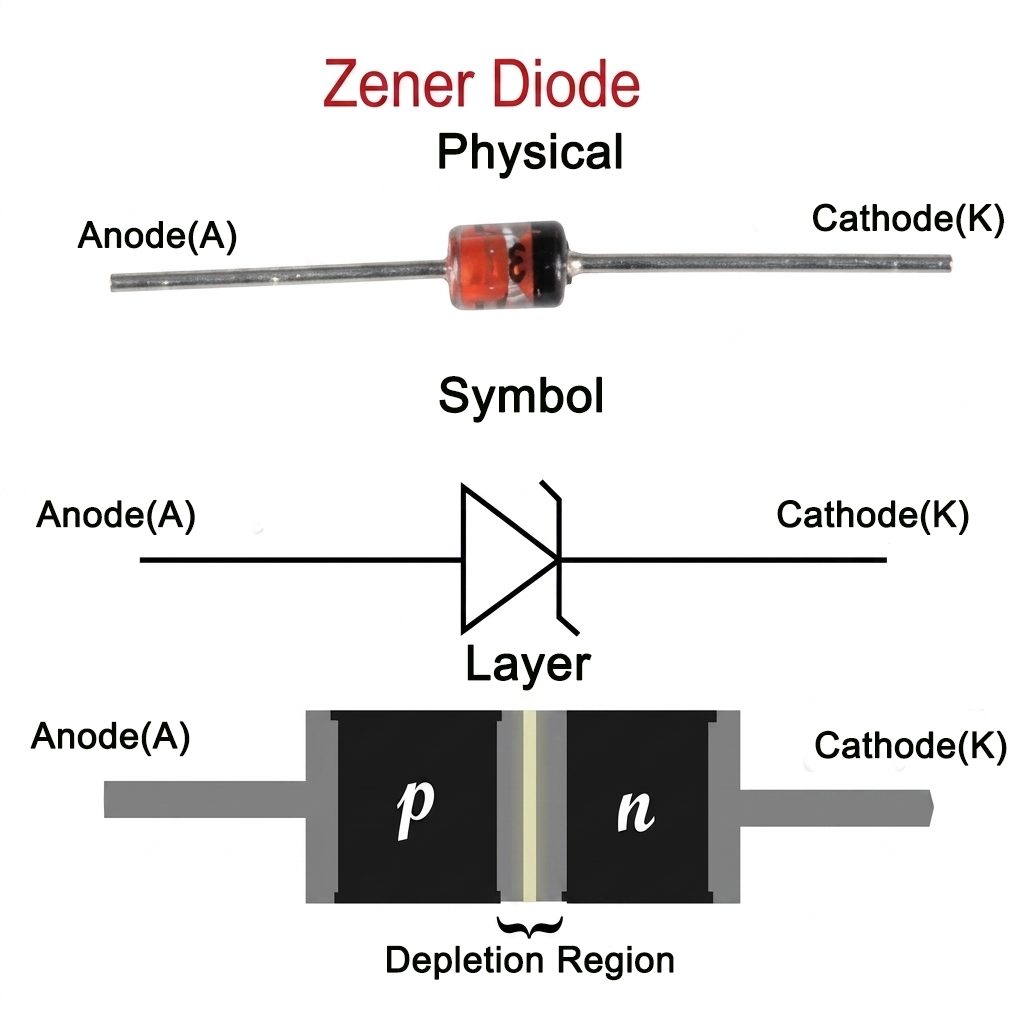
What is a Zener Diode?
A Zener diode is a specially doped p-n junction diode designed to operate reliably in its reverse breakdown region. where they maintain a constant voltage across their terminals known as the Zener voltage. In forward bias, it behaves much like a standard silicon rectifier diode: once the forward voltage is high enough, current flows through the diode, with a typical forward voltage drop of about 0.6–0.7 V for silicon devices.
The key difference appears in reverse bias. A standard p-n junction diode is normally used to block reverse current, and excessive reverse voltage may damage it. A Zener diode, however, is designed to conduct safely when the reverse voltage reaches its specified breakdown value, known as the Zener voltage or breakdown voltage.
At this point, the Zener diode allows reverse current to flow while keeping the voltage across it relatively stable, as long as the current and power dissipation remain within the device’s rated limits.
Zener diode schematic diagram
The Zener voltage, usually written as VZ, is defined under specified test current and temperature conditions. Its value depends on factors such as doping level, semiconductor material, and device geometry.
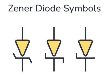
Three ways to draw the Zener Diode Symbol
Let’s consider the Zener diode’s I-V curve below:
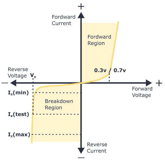
Zener Diode Characteristics (The I-V Graph)
The I-V characteristics curve of a Zener diode is shown in the image above. By studying this graph, it becomes clear why Zener diodes are employed in reverse bias.
By observing the behavior of a Zener diode, you can notice that as the reverse voltage rises, the reverse current also increases gradually until it hits the Zener knee current, IZ (min). At this point, the breakdown effect starts, and the Zener impedance (ZZ), which is the internal resistance of the diode, begins to rapidly decrease as the reverse current increases.
In general, the breakdown voltage of the Zener (VZ) is fairly constant, although it increases slightly with increasing Zener current (IZ). VZ is commonly set at a value of the Zener current known as the IZ (min).
A Zener diode’s ability to maintain almost constant voltage in its breakdown region makes it suitable for regulating voltage even in the simplest voltage regulator applications.
A voltage regulator’s main role is to deliver a steady output voltage to a load connected in parallel. This is even when the supply voltage has ripples or the load current varies. Zener diodes can maintain a constant voltage output as long as their reverse breakdown region holding current does not drop below IZ (min).
How Zener Diodes Work?
Zener diodes are designed to operate in both forward and reverse bias modes, but their unique functionality emerges when reverse biased. This behavior allows them to regulate voltage and protect circuits from overvoltage conditions.
Zener diodes operate differently depending on the biasing condition:
- Forward Bias: Behaves like a regular diode, conducting after ~ 0.7V.
- Reverse Bias Below Vz: Blocks current flow, allowing only minimal leakage.
- Reverse Bias at Vz: Enters controlled breakdown and maintains a stable voltage across the diode.
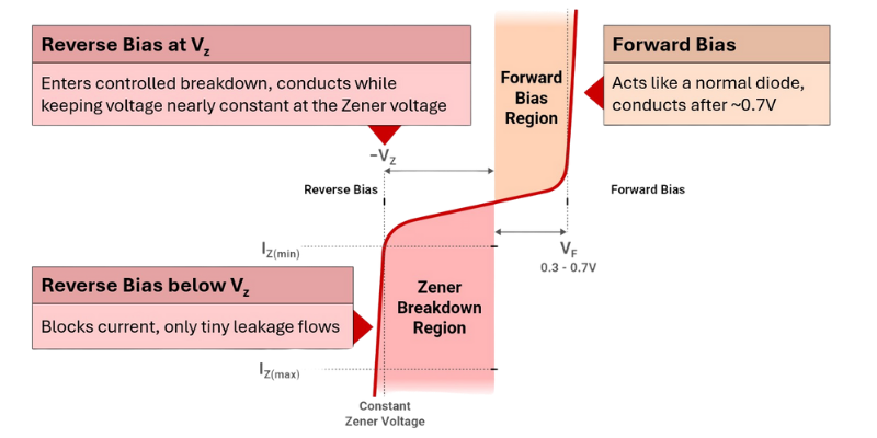
Breakdown Characteristics
When the reverse voltage exceeds the Zener voltage (Vz), the diode enters a breakdown region where it conducts while keeping the voltage nearly constant. This behavior is essential for voltage regulation and protection.
Unique Features of Zener Diodes
Zener diodes possess several distinctive features that set them apart from regular diodes:
- Reverse Breakdown Operation: Unlike regular diodes that primarily operate in the forward bias region, Zener diodes are specifically designed to handle reverse breakdown voltages without being damaged.
- Precise Voltage Regulation: Zener diodes excel at providing accurate voltage regulation. By selecting a Zener diode with a specific breakdown voltage (VZ), a stable voltage reference can be obtained even with fluctuations in load or input voltage.
- Steep Voltage-Current Characteristic: Zener diodes exhibit a steep voltage-current characteristic in the breakdown region. This means that even a small change in current results in minimal variation in the voltage across the diode, leading to better voltage regulation.
- Wide Range of Breakdown Voltages: Zener diodes are available in a wide range of breakdown voltages, making it possible to choose the appropriate diode for various voltage regulation requirements.
- Overvoltage Protection: Zener diodes can act as voltage limiters or clamps, preventing voltage spikes from reaching sensitive components by conducting heavily in the reverse direction when the voltage exceeds the breakdown voltage (VZ).
- Fast Response Time: Zener diodes have a quick response time, making them suitable for applications where rapid voltage regulation or transient suppression is necessary. They can swiftly react to changes in the input voltage and maintain a stable output.
- Compact and Cost-Effective: Zener diodes are relatively small and cost-effective compared to other voltage regulation components, making them an efficient solution for many electronic circuits and devices.
Types of Zener Diode
Let’s explore the types of Zener diodes available in the market, each with its unique characteristics and applications.
Standard Zener Diodes
Standard Zener diodes are the most commonly used type of Zener diodes. They are available in a wide range of breakdown voltages and power ratings. Standard Zener diodes are suitable for general-purpose voltage regulation applications where moderate precision is required.

Zener Diode Arrays
Zener diode arrays are integrated circuits that consist of multiple Zener diodes in a single package. These arrays offer the advantage of space-saving and reduced component count. They are commonly used in applications where multiple voltage references or voltage clamping functions are needed.
Surface Mount Zener Diodes
Surface mount Zener diodes (SMD) are designed for surface mount technology (SMT) applications. They come in compact packages and are suitable for densely populated circuit boards. Surface mount Zener diodes are widely used in modern electronic devices, such as smartphones, tablets, and other portable devices.
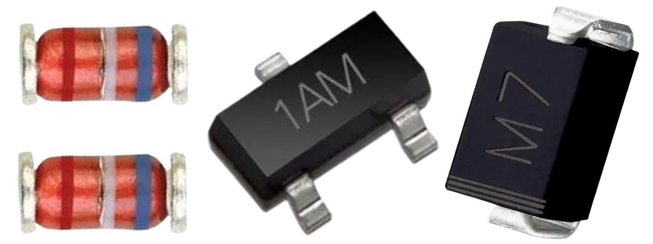
Zener Diodes with Tight Tolerance
Zener diodes with tight tolerance are manufactured with higher precision to provide more accurate voltage regulation. These diodes have narrower tolerances in terms of their breakdown voltage, allowing for finer control over the regulated voltage. They are commonly used in critical applications where precise voltage references are essential, such as in measurement and instrumentation circuits.
Testing and Measurement of Zener Diode
When working with Zener diodes, it is essential to perform testing and measurements to ensure their proper functioning and characteristics. The following are key tests and measurements commonly conducted on Zener diodes:
Forward Voltage Drop Test
This test helps determine the forward voltage drop of a Zener diode. It involves applying a forward bias voltage to the diode within its specified limits and measuring the voltage across it. The measured voltage should be within the expected range, typically a few hundred millivolts.
Reverse Leakage Current Test
The reverse leakage current test evaluates the amount of current that flows through the Zener diode when it is reverse biased. By applying a reverse voltage across the diode and measuring the leakage current, the quality and integrity of the Zener diode can be assessed. Lower leakage currents indicate better performance.
Zener Voltage Test
The Zener voltage test determines the breakdown voltage (VZ) of the Zener diode. It involves applying a reverse voltage to the diode while gradually increasing it until the diode enters the breakdown region. The voltage at which the Zener diode starts conducting significantly is its breakdown voltage. This test ensures that the Zener diode operates within the desired voltage range.
Zener Impedance Measurement
Zener impedance measurement is performed to evaluate the dynamic characteristics of the Zener diode. It measures the change in voltage with respect to the change in current in the Zener diode’s breakdown region. By calculating the dynamic impedance, which is the ratio of voltage change to current change, the stability and linearity of the Zener diode can be assessed.
Key Factors to Consider When Choosing Zener Diodes
To effectively use a Zener diode in your circuit, careful selection and consideration of circuit parameters are necessary. This stepwise guide will walk you through the process of selecting and integrating a Zener diode into your circuit for optimal voltage regulation.
- Determine the Required Voltage Regulation:
Identify the specific voltage regulation requirements of your circuit. Determine the desired output voltage and the acceptable voltage variation or tolerance.
- Calculate the Required Zener Voltage:
Subtract the desired output voltage from the input voltage or power supply voltage to find the voltage drop across the Zener diode. This will give you the required Zener voltage (VZ).
- Choose the Zener Diode:
Look for a Zener diode with a breakdown voltage (VZ) that closely matches your required voltage. Consider factors such as availability, cost, and package size.
- Check the Power Rating:
Calculate the power dissipation (P) across the Zener diode using the formula P = VZ * IZ, where IZ is the Zener current. Ensure that the selected Zener diode can handle the calculated power without exceeding its maximum power rating.
- Verify the Zener Current:
Determine the Zener current (IZ) required for proper operation. It is typically recommended to operate the Zener diode at a current level between 5% and 10% of its rated maximum Zener current (IZM).
- Select the Series Resistor:
Calculate the value of the series resistor (RS) using Ohm’s Law: RS = (VIN – VZ) / IZ, where VIN is the input voltage. Choose a resistor value that is closest to the calculated value and is readily available in the standard resistor values.
- Consider Power Dissipation in the Series Resistor:
Calculate the power dissipation (PR) in the series resistor using the formula PR = (VIN – VZ) * IZ. Make sure the selected resistor can handle this power without exceeding its power rating.
- Add Filtering Capacitor:
Depending on the application, you may need to add a filtering capacitor across the Zener diode to smooth out any voltage variations caused by AC ripple or noise. The value of the capacitor can be determined based on the desired ripple voltage and the frequency of the input signal.
- Ensure Proper Heat Dissipation:
Zener diodes can generate heat during operation, especially if they are dissipating a significant amount of power. Ensure that the Zener diode and any associated components are adequately heat-sinked or cooled to prevent overheating.
- Test and Verify:
Once the Zener diode and supporting circuitry are assembled, test the circuit to verify the desired voltage regulation and stability. Monitor the output voltage and check for any deviations or anomalies.
Remember to refer to the datasheet of the selected Zener diode for detailed specifications, operating conditions, and application guidelines. Additionally, consider any specific requirements or constraints of your circuit and make necessary adjustments accordingly.
Note: It is advisable to consult an experienced engineer or reference reliable resources when designing and implementing circuits involving Zener diodes, especially for complex or critical applications.
Applications of Zener Diodes
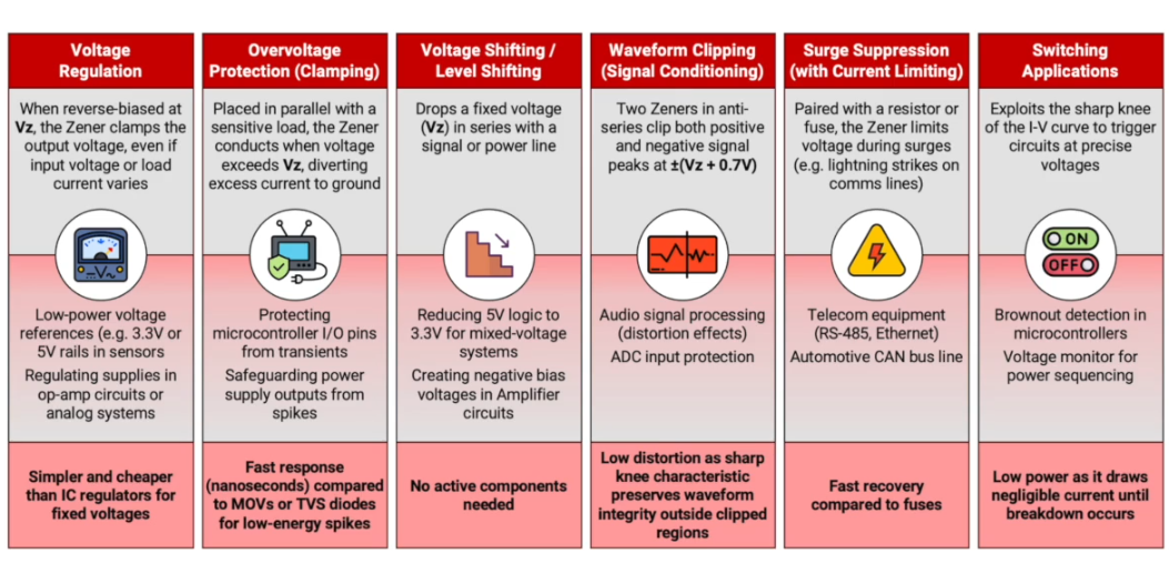
While other components may provide some similar functionalities, Zener diodes excel in offering precise, stable, and controllable performance in these specific applications:
- Voltage Regulation.
- Voltage Reference.
- Overvoltage Protection.
- Voltage Stabilization.
- Signal Clipping and Clamping.
- Waveform Shaping.
- Frequency Stabilization.
- Noise Generation.
- Current Limiting.
Frequently Asked Questions
Can You Connect Multiple Zener Diodes in Series?
It is possible to connect multiple Zener diodes in series and this is usually done to achieve a particular Zener voltage. However, if you are using multiple diodes, you must also monitor the Zener current and ensure the maximum is not exceeded. This is because the maximum allowable Zener current becomes equal to the lowest diode connected in the series. This also means that in a scenario where two Zener diodes are connected in series, one will not exhibit the stated Zener current or voltage if the diodes do not have the same Zener current specifications.
What is the Difference Between a Zener Diode vs a Diode?
A diode is a semiconductor device which conducts in a single direction (unidirectional). Zener diodes are also semiconductor devices, but the key difference is that they conduct in both a forward and reverse bias condition. Another important difference between the two types is doping intensity. Conventional diodes are typically moderately doped, whereas Zener diodes are doped more highly to enable sharper breakdown voltage.
Conclusion
Zener diodes play a vital role in voltage regulation, protection, and other important functions in electronic circuits. With their ability to maintain a constant voltage across their terminals, Zener diodes have found applications in diverse fields, from power supplies and voltage references to surge protection and signal conditioning. Whether you’re a hobbyist or a professional, you can harness their power effectively in your circuit designs by grasping the above-mentioned working principles, characteristics, and circuit considerations.
ثنائيات زينر (Zener Diodes)
فهرس المحتوى
- المقدمة
- ما هو ثنائي زينر؟
- الخصائص الكهربائية لثنائي زينر
- كيف تعمل ثنائيات زينر؟
- الخصائص المميزة لثنائيات زينر
- أنواع ثنائيات زينر
- اختبار وقياس ثنائيات زينر
- حدود ثنائيات زينر والاعتبارات المهمة عند استخدامها
- العوامل الأساسية عند اختيار ثنائي زينر
- تطبيقات ثنائيات زينر
- الأسئلة الشائعة
- الخلاصة
وقت القراءة : حوالي 15 دقيقة
المقدمة
في كثير من الدوائر الإلكترونية، لا تقل أهمية استقرار الجهد عن أهمية التحكم في اتجاه التيار. فقد تعمل الدائرة بصورة طبيعية في الظروف المثالية، لكن ارتفاعات الجهد المفاجئة أو تقلبات مصدر التغذية أو عدم استقرار الجهد المرجعي قد تؤثر بسرعة في أداء الدائرة أو تتسبب في تلف المكونات الحساسة.
وهنا تظهر أهمية ثنائي زينر، إذ يوفر لمصمم الدائرة وسيلة بسيطة وفعالة للتحكم في سلوك الانهيار العكسي والحفاظ على مستوى جهد أكثر استقرارًا ويمكن التنبؤ به داخل الدائرة.
تُعد ثنائيات زينر من المكونات الإلكترونية الأساسية التي تتميز بخصائص تجعلها عنصرًا مهمًا في عدد كبير من التطبيقات العملية. وسواء كنت من هواة الإلكترونيات، أو طالبًا يدرس أساسيات الدوائر، أو مهندسًا يعمل في المجال، فإن فهم طريقة عمل هذه الثنائيات وخصائصها يُعد أمرًا مهمًا لتصميم دوائر أكثر استقرارًا وأمانًا.
في هذا المقال سنستعرض ثنائيات زينر بصورة شاملة، بدءًا من مبدأ عملها وخصائصها الكهربائية، مرورًا بأنواعها واستخداماتها وطرق اختبارها، وصولًا إلى حدودها والعوامل التي ينبغي مراعاتها عند اختيارها وتصميم الدائرة حولها.
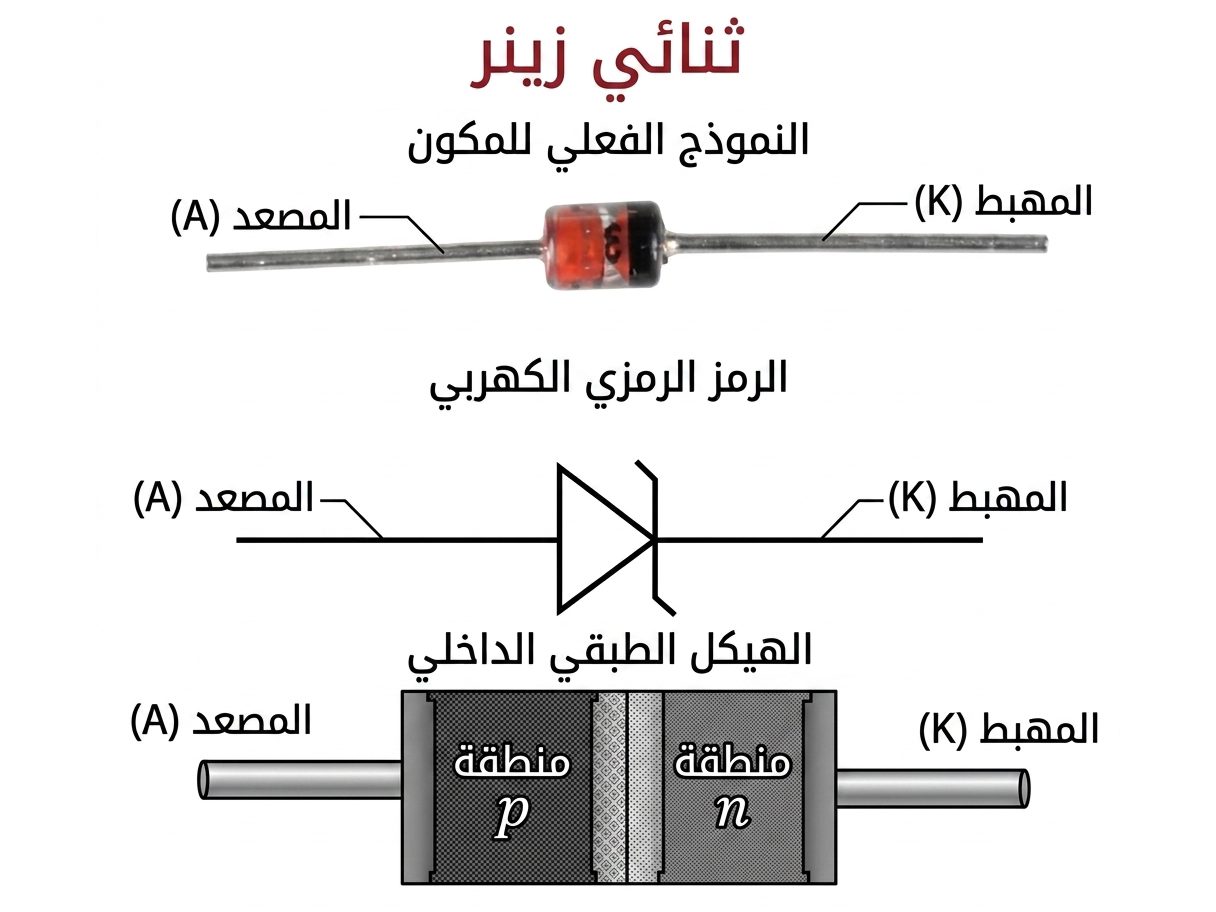
ما هو ثنائي زينر؟
ثنائي زينر هو ثنائي وصلة PN جرى تصنيعه وتطعيمه بطريقة خاصة تسمح له بالعمل بصورة آمنة وموثوقة في منطقة الانهيار العكسي. وعند وصول الجهد العكسي إلى قيمة محددة، يستطيع الثنائي تمرير التيار مع المحافظة على جهد شبه ثابت بين طرفيه، وتُعرف هذه القيمة باسم جهد زينر (VZ) أو جهد الانهيار.
عند توصيل ثنائي زينر في الاتجاه الأمامي، فإنه يتصرف بصورة قريبة من ثنائي السيليكون التقليدي؛ فعندما يتجاوز الجهد الأمامي حد التوصيل، يبدأ التيار بالمرور، ويكون هبوط الجهد الأمامي في أجهزة السيليكون عادةً في حدود 0.6 إلى 0.7 فولت.
أما الاختلاف الأساسي فيظهر عند التوصيل العكسي. فالثنائي التقليدي يُستخدم عادةً لمنع مرور التيار العكسي، وقد يؤدي ارتفاع الجهد العكسي بصورة مفرطة إلى تلفه. أما ثنائي زينر فقد صُمم خصيصًا للعمل في منطقة الانهيار العكسي ضمن حدود التيار والقدرة المسموح بها.
عندما يصل الجهد العكسي إلى قيمة الانهيار المحددة، يسمح ثنائي زينر بمرور تيار عكسي مع إبقاء الجهد عبره قريبًا من قيمة ثابتة نسبيًا، بشرط ألا يتجاوز التيار والقدرة الحدود القصوى المحددة في ورقة البيانات.
يُرمز عادةً إلى جهد زينر بالرمز VZ، ويتم تحديده عند تيار اختبار ودرجة حرارة محددين. وتتأثر قيمة هذا الجهد بعدة عوامل، منها مستوى التطعيم، ونوع مادة أشباه الموصلات، والبنية الهندسية للعنصر.
مخطط ثنائي زينر
ثلاث طرق لرسم رمز ثنائي زينر
يختلف شكل رمز ثنائي زينر في بعض الرسومات والمخططات حسب أسلوب التوثيق، لكن الجزء المميز في الرمز هو شكل خط الكاثود الذي يختلف عن الخط المستقيم المستخدم في رمز الثنائي التقليدي.
الخصائص الكهربائية لثنائي زينر
لفهم طريقة عمل ثنائي زينر بصورة أفضل، يمكن دراسة منحنى العلاقة بين التيار والجهد، أو ما يُعرف بمنحنى I-V.
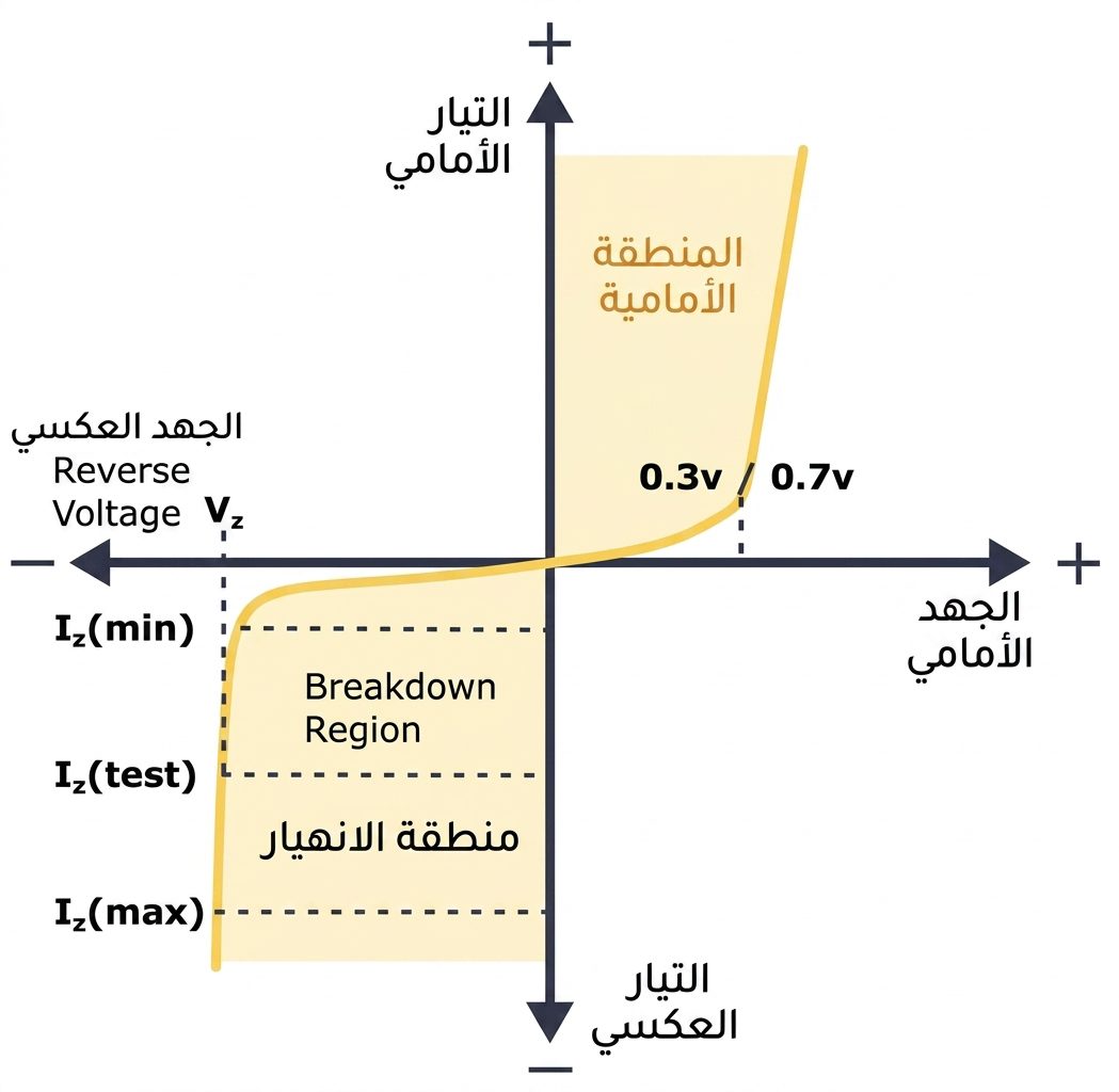
خصائص ثنائي زينر – منحنى I-V
يوضح منحنى الخصائص الكهربائية سبب استخدام ثنائي زينر في الاتجاه العكسي. فعندما يبدأ الجهد العكسي في الارتفاع، يزداد التيار العكسي بصورة محدودة إلى أن يصل إلى منطقة الركبة، حيث يبدأ تأثير الانهيار بالظهور.
عند الوصول إلى تيار الركبة الأدنى IZ(min) يبدأ ثنائي زينر في الدخول بوضوح إلى منطقة الانهيار، وتنخفض معاوقته الديناميكية ZZ مع زيادة التيار العكسي.
وبصورة عامة، يبقى جهد الانهيار VZ قريبًا من قيمة ثابتة، مع إمكانية ارتفاعه بشكل طفيف عند زيادة تيار زينر IZ. وغالبًا ما تُحدد قيمة VZ عند تيار اختبار معين يسمى تيار زينر المحدد.
إن قدرة ثنائي زينر على المحافظة على جهد شبه ثابت داخل منطقة الانهيار تجعله مناسبًا لتطبيقات تنظيم الجهد، حتى في الدوائر البسيطة لمنظمات الجهد.
تتمثل مهمة منظم الجهد في توفير جهد خرج مستقر للحمل المتصل بالدائرة، حتى عند حدوث تغيرات في جهد التغذية أو تغير قيمة تيار الحمل. ويمكن لثنائي زينر القيام بهذه المهمة ما دام تيار التشغيل لا ينخفض عن الحد المطلوب للعمل في منطقة التنظيم.
كيف تعمل ثنائيات زينر؟
يمكن لثنائي زينر العمل في حالتي الانحياز الأمامي والعكسي، إلا أن وظيفته المميزة تظهر عند توصيله في الاتجاه العكسي. وتسمح له هذه الخاصية بتنظيم الجهد وحماية الدوائر من الارتفاعات غير المرغوبة في الجهد.
يختلف سلوك ثنائي زينر حسب حالة الانحياز كما يلي:
- الانحياز الأمامي: يتصرف مثل الثنائي العادي، ويبدأ التوصيل عند جهد أمامي يقارب 0.7 فولت في معظم ثنائيات السيليكون.
- الانحياز العكسي قبل VZ: يمنع مرور التيار تقريبًا، ولا يسمح إلا بتيار تسرب صغير.
- الانحياز العكسي عند VZ: يدخل الثنائي منطقة الانهيار المنضبط، ويعمل على إبقاء الجهد عبر طرفيه قريبًا من قيمة مستقرة.
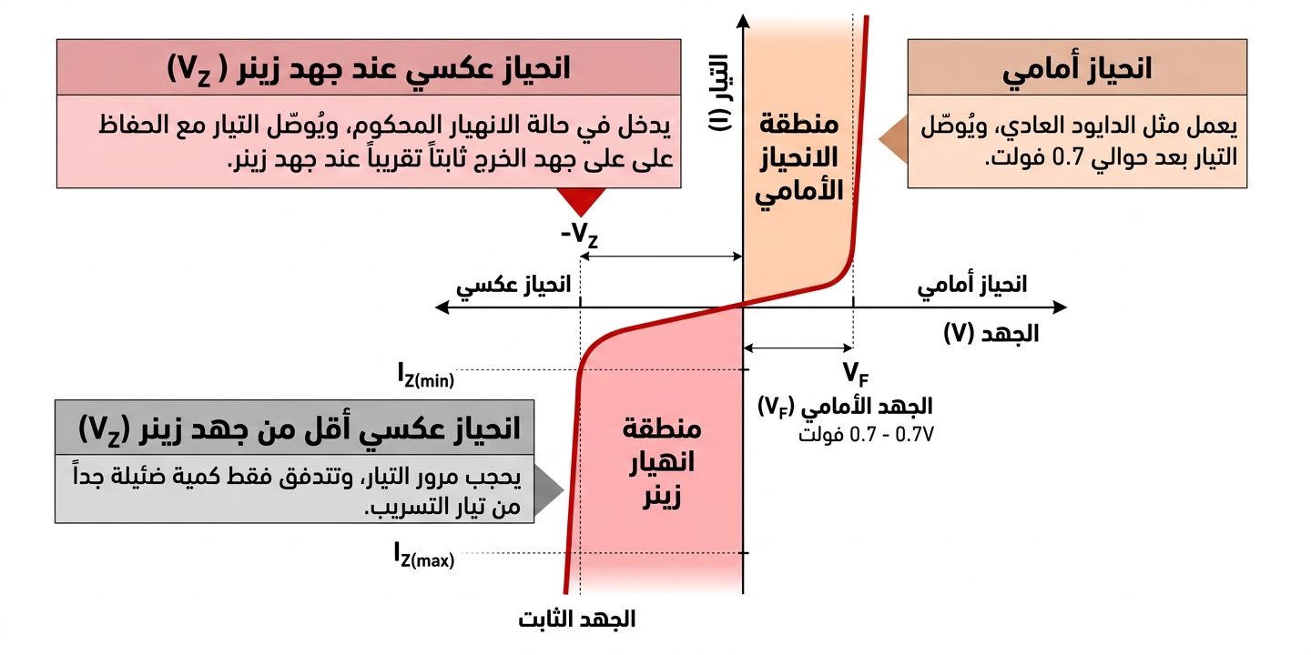
خصائص الانهيار
عندما يتجاوز الجهد العكسي قيمة جهد زينر VZ، يدخل الثنائي منطقة الانهيار ويبدأ بتمرير التيار مع المحافظة على الجهد ضمن نطاق قريب من الثبات. وهذه الخاصية هي الأساس في استخدام ثنائيات زينر لتنظيم الجهد وحماية الدوائر من الارتفاعات المفاجئة.
الخصائص المميزة لثنائيات زينر
تتميز ثنائيات زينر بعدد من الخصائص التي تميزها عن الثنائيات التقليدية، ومن أهمها:
- العمل في منطقة الانهيار العكسي: صُممت ثنائيات زينر للعمل في منطقة الانهيار العكسي بصورة آمنة ضمن حدودها المحددة، بينما لا تُصمم الثنائيات العادية عادةً لهذا النوع من التشغيل المستمر.
- تنظيم دقيق للجهد: يمكن اختيار ثنائي زينر بقيمة جهد انهيار محددة للحصول على جهد مرجعي مستقر نسبيًا رغم تغيرات جهد الدخل أو تيار الحمل.
- منحنى جهد-تيار حاد: في منطقة الانهيار، يؤدي التغير في التيار إلى تغير صغير نسبيًا في الجهد، وهو ما يساعد على تحسين استقرار الجهد.
- مجموعة واسعة من جهود الانهيار: تتوفر ثنائيات زينر بقيم متعددة من جهود الانهيار، مما يسمح باختيار العنصر المناسب لمتطلبات الدائرة.
- الحماية من زيادة الجهد: يمكن استخدام ثنائي زينر كمحدد أو مشبك للجهد، بحيث يبدأ بتوصيل تيار أكبر عند تجاوز الجهد للقيمة المحددة، مما يساعد على حماية المكونات الحساسة.
- سرعة الاستجابة: تتميز ثنائيات زينر بسرعة استجابة مناسبة للعديد من تطبيقات تنظيم الجهد والحماية من النبضات العابرة.
- الحجم الصغير والتكلفة المنخفضة: تتميز هذه المكونات بحجم صغير وتكلفة اقتصادية مقارنة ببعض حلول تنظيم الجهد الأخرى، مما يجعلها مناسبة لعدد كبير من الدوائر.
أنواع ثنائيات زينر
تتوفر ثنائيات زينر بأشكال وأنواع مختلفة لتلبية متطلبات التطبيقات الإلكترونية المتنوعة، ويختلف كل نوع من حيث الحجم والدقة وطريقة التركيب والاستخدام.
ثنائيات زينر القياسية
تُعد ثنائيات زينر القياسية النوع الأكثر شيوعًا، وهي متوفرة بمجموعة واسعة من جهود الانهيار وقدرات القدرة. وتناسب تطبيقات تنظيم الجهد العامة التي لا تتطلب مستويات عالية جدًا من الدقة.
مصفوفات ثنائيات زينر
تحتوي مصفوفات زينر على عدة ثنائيات زينر ضمن حزمة واحدة، مما يساعد على توفير المساحة وتقليل عدد المكونات على لوحة الدائرة. وتُستخدم عندما تكون هناك حاجة إلى أكثر من جهد مرجعي أو وظيفة تحديد للجهد.
ثنائيات زينر للتركيب السطحي SMD
صُممت ثنائيات زينر ذات التركيب السطحي لتناسب تقنيات التجميع السطحي SMT، وتأتي في حزم صغيرة تناسب لوحات الدوائر ذات الكثافة العالية. وتنتشر في الأجهزة الإلكترونية الحديثة مثل الهواتف الذكية والأجهزة اللوحية والمعدات المحمولة.
ثنائيات زينر ذات السماحية الضيقة
تُصنع هذه الثنائيات بدقة أعلى لتوفير جهد انهيار أكثر توافقًا مع القيمة الاسمية. وتكون نسبة السماحية فيها أضيق، مما يجعلها مناسبة للتطبيقات التي تتطلب جهدًا مرجعيًا أكثر دقة، مثل دوائر القياس.
اختبار وقياس ثنائيات زينر
عند التعامل مع ثنائيات زينر، من المهم إجراء الاختبارات والقياسات المناسبة للتأكد من سلامة العنصر ومطابقة خصائصه للقيم المطلوبة في الدائرة. ومن أبرز الاختبارات التي يمكن إجراؤها:
اختبار هبوط الجهد الأمامي
يهدف هذا الاختبار إلى قياس هبوط الجهد على ثنائي زينر عند توصيله في الاتجاه الأمامي. يتم تطبيق جهد أمامي ضمن الحدود المسموح بها ثم قياس الجهد عبر طرفي الثنائي، وينبغي أن تكون النتيجة ضمن النطاق المتوقع، والذي يكون عادةً في حدود عدة أعشار الفولت لثنائيات السيليكون.
اختبار تيار التسرب العكسي
يقيس هذا الاختبار مقدار التيار الذي يمر عبر ثنائي زينر عند توصيله في الاتجاه العكسي قبل الوصول إلى منطقة الانهيار. ويمكن من خلال تطبيق جهد عكسي مناسب وقياس تيار التسرب تقييم حالة العنصر، حيث يشير انخفاض تيار التسرب عادةً إلى سلوك أفضل ضمن ظروف الاختبار المحددة.
اختبار جهد زينر
يحدد هذا الاختبار قيمة جهد الانهيار VZ. ويتم تطبيق جهد عكسي على الثنائي وزيادته تدريجيًا حتى يبدأ التيار بالارتفاع بصورة واضحة. ويُقاس الجهد عند نقطة الاختبار وفق شروط محددة، ثم تتم مقارنته بالقيمة الواردة في ورقة بيانات العنصر.
قياس معاوقة زينر
يساعد قياس معاوقة زينر على معرفة سلوكه الديناميكي داخل منطقة الانهيار، وذلك من خلال دراسة مقدار تغير الجهد مقابل تغير التيار. وتفيد هذه القيمة في تقييم استقرار الجهد ومدى تأثره بتغيرات تيار الحمل.
حدود ثنائيات زينر والاعتبارات المهمة عند استخدامها
رغم الفوائد الكبيرة التي تقدمها ثنائيات زينر في تنظيم الجهد والحماية، فإنها ليست حلًا مثاليًا لكل التطبيقات. لذلك يجب مراعاة مجموعة من القيود والعوامل أثناء تصميم الدائرة.
- تبديد القدرة: لكل ثنائي زينر قدرة قصوى محددة لا ينبغي تجاوزها، لأن زيادة القدرة المبددة قد تؤدي إلى ارتفاع درجة الحرارة وتلف العنصر. لذلك يجب توفير تبريد مناسب عند الحاجة.
- تأثير درجة الحرارة: قد تتغير قيمة جهد الانهيار مع تغير درجة الحرارة. ولهذا يجب أخذ معامل درجة الحرارة في الاعتبار عند تصميم التطبيقات التي تعمل ضمن نطاق حراري واسع.
- المعاوقة الديناميكية: تؤدي المعاوقة الديناميكية إلى تغير بسيط في جهد زينر مع تغير تيار الحمل، ولذلك ينبغي مراعاتها عندما تكون الدائرة بحاجة إلى تنظيم جهد دقيق جدًا.
- التيار العكسي: يوجد تيار تسرب صغير في الاتجاه العكسي، ويجب أخذه في الحسبان خصوصًا في الدوائر منخفضة القدرة.
- الارتفاعات العابرة في الجهد: قد تتعرض الدائرة لنبضات جهد مفاجئة أثناء عمليات التبديل، لذلك يجب اختيار ثنائي زينر قادر على تحمل هذه الظروف ضمن حدود التشغيل المسموح بها.
- تجاوز الجهد اللحظي: قد يظهر ارتفاع قصير في الجهد أثناء بدء التشغيل أو التبديل نتيجة الخصائص الداخلية للدائرة، ولذلك ينبغي مراعاة ذلك في التطبيقات الحساسة.
- سماحية الجهد: تختلف ثنائيات زينر في دقة قيمة جهد الانهيار. وكلما كانت السماحية أضيق، زادت دقة الجهد، وقد ترتفع تكلفة المكون.
- التموج والضوضاء: قد لا يكون ثنائي زينر وحده كافيًا للحصول على جهد نظيف عند وجود تموج أو ضوضاء كبيرة في مصدر التغذية. لذلك قد تكون هناك حاجة إلى مكثفات ترشيح أو مراحل تنظيم إضافية.
العوامل الأساسية عند اختيار ثنائيات زينر
يتطلب اختيار ثنائي زينر مناسب دراسة مجموعة من معايير الدائرة، وليس الاعتماد على قيمة جهد زينر فقط. ويمكن اتباع الخطوات التالية للوصول إلى اختيار مناسب:
- تحديد جهد التنظيم المطلوب:
حدد الجهد الذي تريد الحصول عليه عند خرج الدائرة، بالإضافة إلى مقدار التغير المقبول في هذا الجهد. - تحديد جهد زينر المطلوب:
اختر قيمة VZ المناسبة لجهد الخرج المطلوب وظروف الدائرة، مع مراعاة أن القيمة الفعلية تعتمد على تيار التشغيل ودرجة الحرارة. - اختيار ثنائي زينر المناسب:
ابحث عن عنصر يمتلك جهد انهيار قريبًا من القيمة المطلوبة، مع مراعاة توفره وتكلفته وحجم الحزمة وطريقة تركيبه. - التحقق من قدرة الثنائي:
احسب القدرة المبددة باستخدام العلاقة:
P = VZ × IZ
وتأكد من أن القدرة المحسوبة أقل من القدرة القصوى المسموح بها للثنائي. - التحقق من تيار زينر:
تأكد من أن تيار التشغيل يقع ضمن نطاق التشغيل المناسب للثنائي، وأنه لا يتجاوز الحد الأقصى المسموح به. - اختيار المقاومة المتسلسلة:
يمكن حساب قيمة المقاومة المتسلسلة باستخدام قانون أوم:
RS = (VIN – VZ) / IZ
ثم اختيار أقرب قيمة قياسية مناسبة. - حساب قدرة المقاومة المتسلسلة:
احسب القدرة المبددة في المقاومة باستخدام:
PR = (VIN – VZ) × IZ
وتأكد من أن قدرة المقاومة المختارة مناسبة لهذه القيمة. - إضافة مكثف للترشيح:
في بعض التطبيقات يمكن إضافة مكثف بالتوازي مع ثنائي زينر لتقليل التموج والضوضاء وتحسين استقرار الجهد. - توفير التبريد المناسب:
قد ينتج ثنائي زينر حرارة أثناء التشغيل، خصوصًا عندما يبدد قدرة مرتفعة. لذلك يجب التأكد من وجود تبديد حراري مناسب عند الحاجة. - الاختبار والتحقق:
بعد تجميع الدائرة، قم بقياس جهد الخرج وتيار زينر ومراقبة أي تغيرات أو سلوك غير طبيعي للتأكد من أن الدائرة تعمل ضمن الحدود المطلوبة.
احرص دائمًا على الرجوع إلى ورقة البيانات الخاصة بثنائي زينر المختار لمعرفة مواصفات الجهد والتيار والقدرة ودرجة الحرارة وشروط التشغيل. كما ينبغي مراعاة المتطلبات الخاصة بكل دائرة قبل اعتماد المكون النهائي.
ملاحظة: في التطبيقات المعقدة أو الحرجة، يُفضل الاستعانة بمهندس إلكترونيات متخصص أو الرجوع إلى مصادر تقنية موثوقة عند تصميم الدوائر التي تعتمد على ثنائيات زينر.
تطبيقات ثنائيات زينر
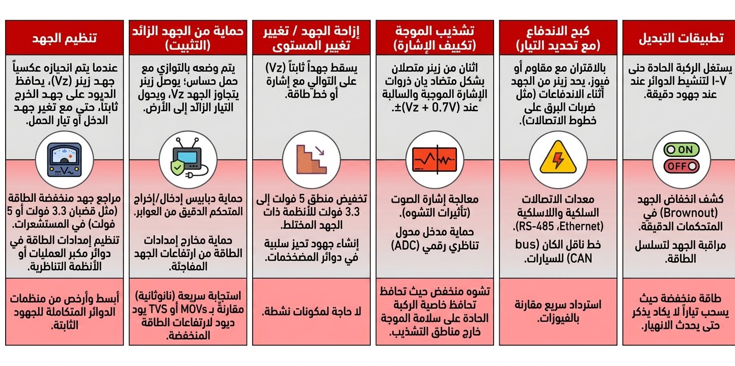
رغم وجود مكونات أخرى يمكنها تنفيذ بعض الوظائف المشابهة، فإن ثنائيات زينر تتميز ببساطتها وقدرتها على توفير أداء مستقر ومتحكم فيه في العديد من التطبيقات، ومن أبرزها:
- تنظيم الجهد.
- توفير جهد مرجعي.
- الحماية من زيادة الجهد.
- تثبيت الجهد.
- قص الإشارات وتحديد مستوياتها.
- تشكيل الموجات.
- تثبيت التردد في بعض التطبيقات.
- توليد الضوضاء في الدوائر المخصصة لذلك.
- الحد من التيار ضمن تصميمات محددة.
الأسئلة الشائعة
هل يمكن توصيل عدة ثنائيات زينر على التوالي؟
نعم، يمكن توصيل عدة ثنائيات زينر على التوالي، وغالبًا ما يُستخدم هذا الأسلوب للحصول على جهد زينر إجمالي أعلى. وعند استخدام عدة ثنائيات، يجب التأكد من أن تيار التشغيل والقدرة المبددة يقعان ضمن الحدود المسموح بها لكل عنصر.
عند توصيل الثنائيات على التوالي، يجب الانتباه إلى اختلاف خصائصها، لأن توزيع الجهد والتيار الفعلي بين العناصر قد لا يكون متطابقًا تمامًا. لذلك ينبغي الرجوع إلى مواصفات كل ثنائي عند تصميم الدائرة.
ما الفرق بين ثنائي زينر والثنائي العادي؟
الثنائي التقليدي مصمم أساسًا للسماح بمرور التيار في اتجاه واحد ومنع مروره في الاتجاه المعاكس ضمن ظروف التشغيل الطبيعية. أما ثنائي زينر فهو أيضًا عنصر شبه موصل، لكنه صُمم للعمل بصورة متحكم بها في الاتجاه العكسي عند الوصول إلى جهد الانهيار المحدد.
ويختلف الثنائيان كذلك في طريقة التطعيم؛ إذ يتم تطعيم ثنائيات زينر بدرجة مناسبة تسمح بتحديد خصائص الانهيار العكسي وجعلها مناسبة لتطبيقات تنظيم الجهد والحماية.
الخلاصة
تلعب ثنائيات زينر دورًا مهمًا في تنظيم الجهد وحماية الدوائر وتنفيذ العديد من الوظائف الإلكترونية الأخرى. وتكمن أهميتها في قدرتها على المحافظة على جهد شبه ثابت عبر طرفيها عند تشغيلها في منطقة الانهيار العكسي ضمن حدودها المسموح بها.
ولهذا السبب تُستخدم في مجموعة واسعة من التطبيقات، بدءًا من دوائر التغذية ومنابع الجهد المرجعي، وصولًا إلى حماية الدوائر من ارتفاعات الجهد ومعالجة الإشارات وتثبيت مستويات الجهد.
وسواء كنت هاويًا للإلكترونيات أو طالبًا أو مهندسًا محترفًا، فإن فهم مبدأ عمل ثنائي زينر وخصائصه وحدوده وطريقة اختيار المكون المناسب سيساعدك على استخدامه بصورة أكثر كفاءة في تصميماتك الإلكترونية.
ومن خلال اختيار جهد زينر المناسب، والتحقق من التيار والقدرة، ومراعاة درجة الحرارة والتسامح والمعاوقة الديناميكية، يمكنك الاستفادة من هذه المكونات البسيطة لبناء دوائر أكثر استقرارًا وحماية للمكونات الحساسة.


Leave a comment
You must be logged in to post a comment.