


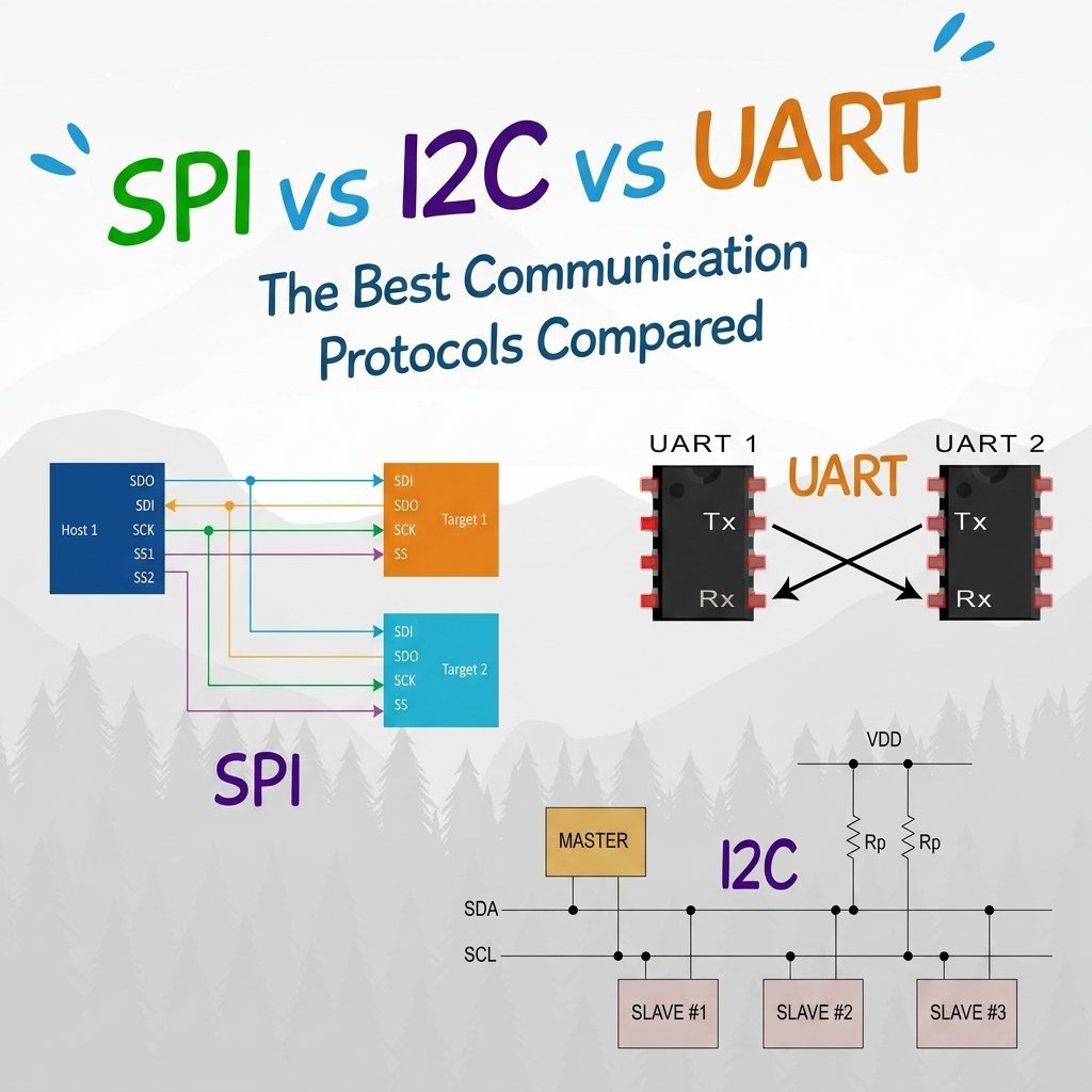
I2C vs SPI vs UART : Choosing the Right Communication Protocol
Contents List
- Introduction
- Inter-integrated-Circuit I2C communication protocol
- Serial Peripheral Interface SPI communication protocol
- Universal Asynchronous Receiver Transmitter UART communication protocol
- Difference between SPI vs I2C vs UART communication protocol
- Tips for choosing the right protocol for your project
- Conclusion
Reading Time Approximately is 20 minute
Introduction
Microcontrollers rarely work alone. They need to communicate with sensors, displays, memory chips, other microcontrollers, and computers. This communication happens through standardized communication interfaces or protocols. With sensors getting faster and circuit boards (PCBs) getting smaller.
Choosing the wrong one can lead to a “noisy” connection, slow performance, or a board that is simply too complicated to build.
Which “language” should your components speak?
The three most common serial communication interfaces in embedded systems are:
- UART – Universal Asynchronous Receiver/Transmitter
- SPI – Serial Peripheral Interface
- I2C – Inter-Integrated Circuit
The comparison of UART vs I2C vs SPI isn’t about which one is “the best.” It’s about how each protocol defines your hardware’s complexity and performance. Your choice will determine how many wires you need to move, how much power you consume, and how fast your data travels.
Our objective ? Help you choose the protocol best suited to your current and future projects.
In this blog, we will discuss the unique technical strengths of each protocol, compare their wiring and speed requirements, and provide a clear decision matrix to help you choose the right foundation for your next embedded project.
Inter-Integrated Circuit I2C communication protocol
What is I2C protocol?
Inter-integrates circuit (I2C) is a synchronous and bidirectional serial communication protocol in half-duplex mode and is a multi-master, multi-slave communication protocol
that uses only two wires:
- SDA (Serial Data Line) – Transfers data between devices.
- SCL (Serial Clock Line) – Synchronizes data transmission.
it allows the connection of multiple devices, masters or slaves, on a bus. In addition, communications are always made at the initiative of a master towards one or more slaves, without direct communication between masters or slaves.
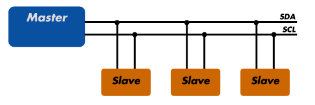
Each device on the I2C bus has a unique address, allowing multiple devices to share the same communication lines.
This protocol is effective for the sensors and modules but not for the PCB device communications. With them, you can connect up to 128 devices to the mainboard while maintaining a clear communication pathway between them. They are ideal for projects that require many different parts to work together (e.g., sensors, pins, expansions, and drivers). Also, I2C speed depends on the speed of data, the quality of the wires, and the amount of external noise.
Specifications of I2C protocol
| Parameter | Details |
|---|---|
| Wires | 2 (SDA, SCL) + GND |
| Speed | 100 kHz to 3.4 MHz |
| Direction | Half-duplex (one direction at a time) |
| Devices | Up to 127 on one bus (7-bit addressing) |
| Clock | Synchronous (master provides clock) |
| Acknowledgment | Built-in ACK/NACK after each byte |
Basic principles of I2C protocol
The I2C protocol, a two-way communication system, is divided into two main operations: reading (from master to slave) and writing (from slave to master). Each operation follows distinct key steps to ensure smooth and accurate data transmission

Reading (Slave toward Master) :
- START condition : Reading begins with a START condition initiated by the master. We achieve this by lowering the data line (SDA) low while keeping the clock line (SCL) high. This distinct signal tells all devices on the bus that the master is about to begin a new transmission.
- Slave Address and Read Bit : The master then sends the address of the targeted slave on the bus. This address is followed by a control bit, set to 1 to indicate a read operation. Each bit is transmitted sequentially, with a change on the rising edge of each clock pulse.
- Acknowledgment (ACK/NACK) : After receiving its address, the slave responds with an acknowledgment (ACK) bit if ready to communicate, pulling the SDA line low for one clock cycle. A non-acknowledgment (NACK) would be signaled by leaving the SDA line high.
- Receipt of Data : The slave then begins to send the data to the master, byte by byte.
- Acquittal by the Master : After receiving each byte, the master sends an acknowledgment (ACK) bit, pulling the SDA line low, to signal the slave to continue sending data. If the master does not wish to receive more data, it sends a non-acknowledgement (NACK) after the last byte received.
- STOP condition : The communication ends with a STOP condition. The master generates this signal by switching the SDA line from low to high while the SCL line is high. This change indicates the end of the reading session and frees the bus for other communications
Writing (Master toward Slave) :
- START condition : Just like in the reading process, writing begins with a START condition initiated by the master. This signal is generated by pulling the data line (SDA) low, while the clock line (SCL) is held high, signaling the start of a transmission.
- Slave Address and Write Bit : The master then transmits the address of the recipient slave, followed by a control bit set to 0 to indicate a write operation.
- Acknowledgment (ACK/NACK) : The slave, after receiving and recognizing its address, sends an acknowledgment bit (ACK) by pulling the SDA line low for one clock cycle. A non-acknowledgment (NACK) would be indicated by an SDA line held high.
- Sending Data by the Master : After receiving the ACK from the slave, the master starts sending the data, byte by byte.
- Acknowledgment by the Slave : At the end of each byte transmitted, the slave acknowledges reception by sending an acknowledgment bit (ACK), thus confirming successful reception of the byte. If there is a problem, a NACK can be sent.
- STOP/RESTART condition : The operation ends with a STOP condition, generated by the master by passing the SDA line from low to high while SCL is high, thus indicating the end of transmission and release of the bus. If the master wishes to continue with another write or read operation, it can generate a RESTART condition.
Thus, this distinction between read and write modes in the operation of I2C allows for efficient two-way communication between devices connected to the bus.
Advantages of using I2C protocol
- Has a low pin/signal count even with numerous devices on the bus
- Flexible, as it supports multi-master and multi slave communication.
- Simple as it only uses 2 bidirectional wires to establish communication among multiple devices.
- Adaptable as it can adapt to the needs of various slave devices.
- Support multiple masters.
Disadvantages of using I2C Protocol
- Slower speed as it requires pull-up resistors rather than push-pull resistors used by SPI. It also has an open-drain design = limited speed.
- Requires more space as the resistors consume valuable PCB real estate.
- May become complex as the number of devices increases.
Best Applications of I2C Protocol
I2C is the perfect “manager” for low-to-medium speed components. It is almost always used for:
- Environment Sensors humidity and pressure sensors.
- Temperature sensors (LM75, BME280)
- Real-Time Clocks (RTC): (DS1307, DS3231) To keep track of the date and time.
- Small Displays: Tiny OLED screens (SSD1306) that only need to show a bit of text.
- Memory chips (EEPROM)
- Accelerometers and gyroscopes (MPU6050)
- Configuration: Setting the volume or brightness on other chips.
I2C protocol in Microcontroller
Raspberry Pi’s 4 channel 16 bit ADC
It is the Seed product that is compatible with the Raspberry Pi. This 16-bit ADC is used when a more precise ADC is required in the circuit.
I2C Driver/Adapter
It is an open-source tool that is easy to use. Usually, it is used for controlling I2C devices. It is compatible with all OS. It offers a built-in color screen that provides the live dashboard of I2C activity. Thus, when an I2C drive connects to the I2C bus, it displays the traffic on the screen. Besides, it can help to debug the I2C issues and troubleshoot them.
I2C Arduino
I2C Communication interfaces between two Arduino boards are also possible. It is used for short-distance communication interfaces and uses the synchronized clock pulse. This I2C Arduino is used while communicating with the other sensors and devices that need to send the information to the Master.
PCF 8574
It provides the general purpose remote I/O expansion through two bidirectional I2C buses.
Serial Peripheral Interface SPI communication protocol
What is SPI protocol?
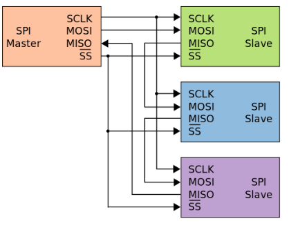
The master-slave architecture of SPI has a single master device and microcontroller, while the slaves are the peripherals like the GSM modem, sensors, GPS, etc.
Operates at full-duplex where data can be sent and received simultaneously.
SPI supports two communication interface modes; point-to-point and standard mode. In point-to-point mode, a single controller follows the single slave, while in standards mode, a single master controller can communicate with two slave devices enabling the select chip lines.
SPI uses four wires, MISO, MOSI, SS, and CLK. Their wires help in the communication interfaces between the master and slave devices. The master devices both read and write the data. SPI serial bus allows multiple slaves to interface with the master device thus, SPI protocol’s major benefit is the speed used where speed is crucial. Furthermore, SPI protocol’s applications include SD cards, display modules, etc.
Specifications of SPI protocol
| Parameter | Details |
|---|---|
| Wires | 4 (MOSI, MISO, SCLK, SS) + GND |
| Speed | Up to tens of MHz (very fast) |
| Direction | Full-duplex |
| Devices | 1 master, multiple slaves (1 SS pin per slave) |
| Clock | Synchronous (master provides clock) |
| Overhead | No addressing, no acknowledgment (minimal overhead) |
Basic principle of SPI protocol

- Clock Signal Generation : The master starts the communication by generating a clock signal which synchronizes the data exchange.
- Slave Selection : The master activates the desired slave by lowering the SS line to a low voltage level.
- Data Exchange : The master begins by sending data to the slave through the MOSI line, bit by bit, often starting with the most significant bit. At the same time, the slave can also send data to the master through the MISO line, usually starting with the least significant bit.
- Simultaneous Communication : Unlike a simple command-and-response model, SPI allows simultaneous two-way communication. As long as the SS line remains enabled, the master and slave can continue to exchange data at the same time, allowing efficient and fast data transmission in both directions.
Advantages of using SPI protocol
- The protocol is simple as there is no complicated slave addressing system like I2C.
- It is the fastest protocol compared to UART and I2C.
- No start and stop bits unlike UART which means data can be transmitted continuously without interruption
- Separate MISO and MOSI lines which means data can be transmitted and received at the same time
Disadvantages of using I2C Protocol
- More Pin ports are occupied, the practical limit to a number of devices.
- There is no flow control specified, and no acknowledgement mechanism confirms whether data is received unlike I2C
- Uses four lines – MOSI, MISO, NCLK, NSS
- No form of error check unlike in UART (using parity bit)
- Only 1 Master
Best Applications of SPI protocol
- SD Cards: Reading and writing large files quickly.
- TFT Displays: Pushing pixels fast enough to show smooth animations.
- High-Speed ADCs: Converting analog signals (like high-fidelity audio) into digital data without losing a single note.
- Flash Memory: Storing and retrieving the actual software code that runs your device.
SPI in Microcontrollers
SPI Driver/Adapter
It is one of the easy tools to control SPI devices. It is compatible with all operating systems. The live logic analyzer displays the SPI traffic on the screen. The operating voltage of the SPI driver is 3.3 V -5 V.
MCP 3008
It is a 10-bit ADC having 8 channels. Moreover, it connects to the Raspberry Pi with the help of an SPI serial connection.
SPI Seeeduino V 4.2
A Master Arduino and a slave Arduino can communicate using SPI serial communication interfaces with Arduino. The main aim is to communicate over a short distance at a higher speed.
Universal Asynchronous Receiver Transmitter UART communication protocol
What is UART protocol?
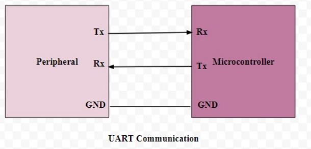
UART is an asynchronous communication protocol that transmits data without a clock signal. Instead, it uses a predefined baud rate to synchronize communication. UART requires two lines:
- TX (Transmit) – Sends data from one device to another.
- RX (Receive) – Receives data from the transmitting device.
Specifications of UART protocol
| Parameter | Details |
|---|---|
| Wires | 2 (TX, RX) + GND |
| Speed | Typically up to 115200 bps, some up to several Mbps |
| Direction | Full-duplex (send and receive simultaneously) |
| Devices | Point-to-point (2 devices only) |
| Clock | No clock signal (asynchronous) |
| Distance | Short (PCB level), longer with RS-232/RS-485 transceivers |
Basic principle of UART protocol

Detailed operating mode of the UART
- High State Transmission Line : Usually, the transmission line is kept at a high voltage level in the absence of data transmission.
- Starting the Transmission : To begin transmission, the transmitting UART pulls the transmission line up and down for one clock cycle. The UART receiver detects this voltage change and starts reading the bits at the baud rate frequency.
- Baud Rate : The baud rate, which measures data transfer speed, should be approximately the same for both UARTs. The most common baud rates are 9600, 19200, 38400, 57600 and 115200 bits per second. The baud rate difference between the two UARTs must not exceed 10%.
- Data Frame : The frame contains the actual data transferred, usually sent with the least significant bit first.
- Parity Bit : The parity bit is used for error detection. It allows the receiving UART to determine if any changes occurred during transmission.
- End Bits : To signal the end of the data packet, the transmitting UART raises the transmission line high for at least two bit durations.
Advantages of Using UART protocol
- Simple to operate, well documented as it is a widely used method with a lot of resources online
- No clock needed
- Parity bit to allow for error checking
Disadvantages of Using UART protocol
- Size of the data frame is limited to only 9 bits
- Cannot use multiple master systems and slaves
- Baud rates of each UART must be within 10% of each other to prevent data loss.
- Low data transmission speeds
Best Applications of UART protocol
UART is widely used for point-to-point communications in various fields:
- Connections between Microcontrollers and Peripherals : For simple and direct data exchange.
- GPS Modules and Serial Interfaces with Computers : For reliable, low-complexity communications.
- Industrial Machines : UART is commonly used in industrial equipment for robust communications.
- Use of RS Standards (such as RS-232, RS-485).
These standards enable UART communication over longer distances and offer the possibility of creating multi-slave networks using appropriate transceivers, thus increasing the flexibility and breadth of UART applications.
Example of UART in Microcontroller
USB to UART 5V
Designed to simplify USB-to-serial communication, these USB-to-serial UART interfaces provide a USB-to-serial connection. Using a USB host controller efficiently reduces the number of external components while using the minimum amount of USB bandwidth. Based on the CH340 USB bus converter can convert USB files into serial files. It can be used for USB to UART 5 V converters.
USB CP2102 Serial Converter
RS-232 designs can easily be updated to USB using this highly-integrated USB to UART bridge controller. USB connectivity is provided to UART-equipped devices. Arduino/Seeeduino boards can be upgraded by computer with this USB CP2102 Serial Converter.
UART Seeeduino V4.2
The Arduino boars contain at least one serial port that usually communicates the digital pins Tx and Rx through USB. It is compatible to work with Arduino board. This board can be programmed through a Micro USB cable.
Base Shield V2
There is no doubt that Arduino Uno is the most popular Arduino board. However, it can be a bit frustrating once you need to connect many sensors and LEDs to the board, and your jumper wires are tangled. This product eliminates the need for breadboards and jumpers. Adding all the grove modules to the Arduino Uno is convenient since the baseboard has grove connectors.
Difference between SPI vs I2C vs UART communication protocol
Speed
SPI protocol is faster among all three communication interfaces, whereas UART is the slowest.
Number of Devices
SPI can take an unlimited number of devices as long as hardware complexity is not a problem. At the same time, I2C can take 127 devices, but UART support just 2 devices.
Number of Wires
For connecting Master and slave devices, SPI has 4 wires, I2C has 2 wires, and the UART has only one.
Complexity
UART beats both SPI and I2C in terms of complexity. It is simple compared to the remaining two protocols, whose complexity increases with the number of devices.
Communication Types
UART is one of the asynchronous communication interface types with no clock signal, whereas I2C and SPI are synchronous protocols.
| Parameter | UART | I2C | SPI |
|---|---|---|---|
| Full Form | Universal Asynchronous Receiver/Transmitter | Inter-Integrated Circuit | Serial Peripheral Interface |
| Communication Type | Asynchronous | Synchronous | Synchronous |
| Main Signals / Pins | TX, RX | SDA, SCL | MOSI, MISO, SCLK, CS/SS |
| Wire Count | 2 | 2 | 4+ |
| Clock Signal | No common clock; both devices use their own clocks | Shared clock on SCL | Shared clock on SCLK |
| Typical / Maximum Data Rate | Typically up to ~1 Mbps; depends on UART hardware | 100 kbps, 400 kbps, 1 Mbps, 3.4 Mbps; higher modes exist | Commonly several Mbps to tens of Mbps; can exceed 50 Mbps depending on hardware |
| Duplex Mode | Full-duplex | Half-duplex | Full-duplex |
| Number of Masters | Usually one-to-one | One or multiple masters | Usually one master, though multi-master is possible in some implementations |
| Number of Slaves / Devices | Usually one-to-one | Multiple devices on the same bus | Multiple devices using separate CS/SS lines |
| Device Addressing | No addressing; normally point-to-point | 7-bit or 10-bit device addressing | No built-in addressing; CS/SS selects the device |
| Slave Selection | Not required | Address-based | Dedicated CS/SS line for each slave |
| Data Framing / Protocol | Start bit, data bits, optional parity, stop bit | START, address, data, ACK/NACK, STOP | Clocked data transfer; exact frame/command format depends on the peripheral |
| Hardware Complexity | Low | Medium | Low to medium |
| Pin Requirement | Low | Very low | Higher |
| Communication Distance | Suitable for short-distance communication; longer distances possible with suitable transceivers | Generally short-distance PCB/bus communication | Generally short-distance PCB communication |
| Speed | Low | Medium | High |
| Best Use Case | Debugging, GPS, Bluetooth modules, PC-to-device communication | Sensors, EEPROMs, RTCs, multiple low-speed peripherals | Displays, ADC/DACs, memory, high-speed sensors |
| Main Advantage | Simple and easy to implement | Only two wires for multiple devices | Very high speed and full-duplex communication |
| Main Disadvantage | No built-in multi-device bus addressing | Slower and more protocol overhead | Requires more wires/CS lines and has no standard device-addressing scheme |
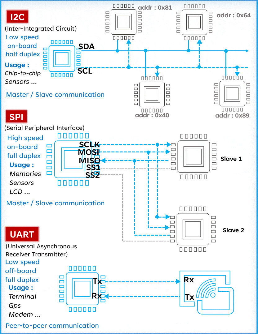
When you are deep in the middle of embedded application development, you often have to make a quick trade-off. Do you want fewer wires, or do you need lightning-fast speed? This head-to-head comparison of UART vs I2C vs SPI helps you see the “price” you pay for performance.
Tips for choosing the right protocol for your project
All three communication peripherals have their specific upsides and downsides. The selection of the best protocol for your project depends on your requirements.
Scenario A: I have limited pins on my microcontroller.
The Suitable: I2C
If you are using a tiny chip with only a few available pins, or if your circuit board is already crowded with traces, I2C is the hero. Because it uses a “bus” system, you can connect a dozen different sensors, temperature, light, pressure, and more—using just the same two pins (SDA and SCL). It keeps your board clean and your pin count low.
Scenario B: I need to stream 60fps video to a display.
The Suitable: SPI
When you are moving massive amounts of data, like refreshing pixels on a screen or reading high-resolution images from an SD card, SPI is the only choice. UART is too slow, and I2C’s “addressing” overhead takes up too much time. SPI’s high-speed “push-pull” design allows it to move data fast enough to keep your animations smooth and your lag low.
Scenario C: I need to talk to a sensor 10 meters away.
The Suitable: UART / RS-232
Conclusion
- Through this article, we have explored the subtleties and specificities of the three major communication protocols: I2C, SPI and UART. Each of them features a unique balance of speed, complexity, usability and duplex capabilities, providing varied solutions for communication challenges in electronics projects.
- I2C stands out for its simplicity and ability to manage multiple slaves with a minimum of pins, making it ideal for short distance configurations.
- The SPI, with its high speed and full-duplex mode, is perfect for fast and efficient data transfers in systems where space is not a major issue.
- UART, versatile and robust, shines in long-distance communications and less speed-demanding configurations.
- By understanding the strengths and limitations of each protocol, you can choose the one that best fits your project requirements. We strongly encourage you to experiment with these protocols and expand your knowledge. Practice and exploration are the keys to mastering these essential tools of electronic communication.
مقارنة بين I2C وSPI وUART: كيف تختار بروتوكول الاتصال المناسب؟
فهرس المحتوى
وقت القراءة: حوالي 20 دقيقة
مقدمة
نادرًا ما تعمل المتحكمات الدقيقة بمفردها؛ فهي تحتاج إلى التواصل مع الحساسات، والشاشات، وشرائح الذاكرة، والمتحكمات الأخرى، وأجهزة الحاسوب. ويتم هذا التواصل من خلال واجهات وبروتوكولات اتصال قياسية.
ومع ازدياد سرعة الحساسات وصغر حجم لوحات الدوائر المطبوعة (PCB)، أصبح اختيار بروتوكول الاتصال المناسب أكثر أهمية. فالاختيار غير المناسب قد يؤدي إلى اتصال غير مستقر، أو سرعة غير كافية، أو تعقيد غير ضروري في تصميم الدائرة.
إذن، ما “اللغة” المناسبة التي ينبغي أن تتحدث بها مكونات مشروعك؟
من أكثر واجهات الاتصال التسلسلي استخدامًا في الأنظمة المضمنة:
- UART – وحدة الإرسال والاستقبال غير المتزامن.
- SPI – الواجهة التسلسلية للأجهزة الطرفية.
- I2C – دائرة الاتصال بين الدوائر المتكاملة.
المقارنة بين UART وI2C وSPI لا تتعلق بالبحث عن بروتوكول واحد هو “الأفضل” دائمًا، وإنما باختيار البروتوكول الذي يناسب طبيعة المشروع. فاختيارك سيؤثر في عدد الأسلاك المطلوبة، وعدد منافذ المتحكم المستخدمة، واستهلاك الطاقة، وسرعة نقل البيانات، ومدى تعقيد النظام.
الهدف من هذا الدليل هو توضيح نقاط القوة التقنية لكل بروتوكول، ومقارنة متطلبات التوصيل والسرعة وطريقة الاتصال، ثم تقديم طريقة عملية تساعدك على اختيار البروتوكول الأنسب لمشروعك.
بروتوكول I2C للاتصال بين الدوائر المتكاملة
ما هو بروتوكول I2C؟
يُعد I2C بروتوكول اتصال تسلسلي متزامن وثنائي الاتجاه، ويُستخدم على نطاق واسع لربط عدة دوائر ومكونات إلكترونية باستخدام خطي اتصال فقط. ويمكن أن يدعم النظام أكثر من متحكم رئيسي وأكثر من جهاز تابع، وفقًا لتصميم النظام ودعم العتاد.
يعتمد I2C على خطين رئيسيين:
- SDA: خط البيانات التسلسلي، ويتم من خلاله نقل البيانات.
- SCL: خط الساعة، ويستخدم لمزامنة عملية نقل البيانات.
الفكرة الأساسية في I2C هي أن عدة أجهزة يمكنها مشاركة خطي SDA وSCL نفسيهما. ويملك كل جهاز عنوانًا خاصًا، مما يسمح للمتحكم الرئيسي بتحديد الجهاز الذي يريد التواصل معه دون الحاجة إلى خط منفصل لكل جهاز.
ولهذا السبب يُعد I2C مناسبًا جدًا عند توصيل مجموعة من الحساسات والدوائر الطرفية التي لا تحتاج إلى معدلات نقل بيانات عالية جدًا، مثل حساسات الحرارة والضغط والرطوبة، ودوائر الساعة الحقيقية، وشرائح EEPROM، وبعض الشاشات الصغيرة.
مواصفات بروتوكول I2C
المعيار التفاصيل عدد الأسلاك سلكان رئيسيان: SDA وSCL، بالإضافة إلى GND السرعة 100 كيلوهرتز، 400 كيلوهرتز، 1 ميغاهرتز، وحتى 3.4 ميغاهرتز في أوضاع محددة الاتجاه اتصال ثنائي الاتجاه، ولكن نقل البيانات يتم في اتجاه واحد في كل لحظة عدد الأجهزة حتى 127 عنوانًا في نظام العنونة ذي 7 بت، مع مراعاة العناوين المحجوزة وتعارض العناوين الساعة متزامنة، حيث يوفر المتحكم الرئيسي إشارة الساعة التأكيد يتضمن ACK/NACK لتأكيد استقبال البيانات أو الإشارة إلى عدم قبولها آلية عمل بروتوكول I2C
تعتمد عملية الاتصال في I2C على مجموعة من الحالات والإشارات المنظمة، سواء كان المتحكم الرئيسي يرسل بيانات إلى جهاز آخر أو يقرأ بيانات منه.
قراءة البيانات من الجهاز التابع إلى المتحكم الرئيسي
- حالة START: يبدأ المتحكم الرئيسي عملية الاتصال بتوليد إشارة البدء، وذلك عندما ينتقل SDA إلى المستوى المنخفض بينما يبقى SCL مرتفعًا.
- إرسال عنوان الجهاز وأمر القراءة: يرسل المتحكم عنوان الجهاز المطلوب، ثم يحدد أن العملية المطلوبة هي قراءة.
- إشارة ACK أو NACK: يرسل الجهاز المستهدف إشارة ACK لتأكيد استقباله العنوان، أو NACK في حالة عدم الاستجابة.
- إرسال البيانات: يبدأ الجهاز التابع بإرسال البيانات إلى المتحكم الرئيسي على شكل بايتات متتالية.
- التأكيد من المتحكم الرئيسي: بعد استقبال كل بايت، يرسل المتحكم ACK إذا كان يريد استمرار القراءة. أما عند الوصول إلى آخر بايت، فيرسل NACK للإشارة إلى انتهاء الاستقبال.
- حالة STOP: ينهي المتحكم الاتصال بتوليد إشارة التوقف، مما يحرر ناقل الاتصال.
كتابة البيانات من المتحكم الرئيسي إلى الجهاز التابع
- حالة START: يبدأ المتحكم الرئيسي الاتصال بإرسال إشارة البدء.
- إرسال العنوان وأمر الكتابة: يرسل عنوان الجهاز المستهدف مع تحديد أن العملية هي كتابة.
- إشارة ACK أو NACK: يرسل الجهاز التابع ACK بعد استلام العنوان إذا كان مستعدًا للاتصال.
- إرسال البيانات: يرسل المتحكم البيانات إلى الجهاز التابع بايتًا تلو الآخر.
- تأكيد الاستقبال: يرسل الجهاز التابع ACK بعد استقبال كل بايت للتأكد من نجاح عملية النقل.
- STOP أو RESTART: يمكن إنهاء الاتصال باستخدام STOP، أو الانتقال إلى عملية أخرى مباشرة باستخدام RESTART.
تمنح هذه الآلية I2C مرونة كبيرة في التعامل مع مجموعة من الأجهزة التي تشترك في الناقل نفسه، مع المحافظة على عدد منخفض من أرجل المتحكم.
مميزات استخدام I2C
- يحتاج إلى عدد قليل من الأرجل حتى عند توصيل عدة أجهزة.
- يسمح لعدة أجهزة بمشاركة ناقل الاتصال نفسه.
- يحتوي على نظام عنونة يسهّل تحديد الجهاز المطلوب.
- يوفر آلية ACK/NACK للتحقق من استلام البيانات.
- مناسب جدًا للحساسات والدوائر الطرفية منخفضة ومتوسطة السرعة.
عيوب استخدام I2C
- أبطأ من SPI في معظم التطبيقات عالية السرعة.
- يعتمد على مقاومات السحب لأعلى، مما يؤثر في زمن صعود الإشارة وسرعة الناقل.
- قد يصبح تصميم الناقل أكثر تعقيدًا عند زيادة عدد الأجهزة أو طول الأسلاك.
- يجب مراعاة سعة الناقل وقيمة مقاومات السحب وجودة التوصيلات، خصوصًا عند السرعات المرتفعة.
أفضل استخدامات I2C
- حساسات درجة الحرارة والرطوبة والضغط.
- دوائر الساعة الحقيقية RTC مثل DS1307 وDS3231.
- الشاشات الصغيرة، مثل شاشات OLED المعتمدة على SSD1306.
- شرائح الذاكرة EEPROM.
- مقاييس التسارع والجيروسكوب، مثل MPU6050.
- توسعة منافذ الإدخال والإخراج.
- إعداد خصائص الدوائر، مثل مستوى الصوت أو شدة الإضاءة.
أمثلة على I2C في المتحكمات والأنظمة المضمنة
- محولات ADC المعتمدة على I2C: يمكن استخدامها عندما تكون دقة التحويل التناظري إلى الرقمي أعلى من قدرة المحول المدمج في المتحكم.
- أدوات اختبار وتصحيح I2C: تساعد في مراقبة حركة البيانات على الناقل واكتشاف مشكلات العناوين أو الإشارات أو التوصيلات.
- الاتصال بين لوحات Arduino: يمكن استخدام I2C لتبادل البيانات بين لوحتين أو أكثر، خصوصًا عندما تكون سرعة الاتصال العالية غير مطلوبة.
- PCF8574: دائرة لتوسعة منافذ الإدخال والإخراج العامة عبر واجهة I2C.
بروتوكول SPI للواجهة التسلسلية للأجهزة الطرفية
ما هو بروتوكول SPI؟
SPI هو بروتوكول اتصال تسلسلي متزامن صُمم أساسًا للتواصل السريع بين المتحكمات والأجهزة الطرفية. ويُستخدم بكثرة مع شاشات العرض، وشرائح الذاكرة، وبطاقات SD، ومحولات ADC وDAC، والحساسات عالية السرعة.
يعتمد SPI التقليدي على أربعة خطوط رئيسية:
- MOSI: خط إرسال البيانات من المتحكم إلى الجهاز الطرفي.
- MISO: خط إرسال البيانات من الجهاز الطرفي إلى المتحكم.
- SCLK: خط الساعة الذي يولده المتحكم الرئيسي.
- CS/SS: خط اختيار الجهاز الطرفي المطلوب التواصل معه.
ومن أهم مزايا SPI أنه يعمل عادةً بطريقة Full-Duplex، أي يمكن إرسال البيانات واستقبالها في الوقت نفسه. كما يمكن توصيل عدة أجهزة طرفية بالمتحكم، مع استخدام خط CS مستقل لكل جهاز في التوصيل التقليدي.
مواصفات بروتوكول SPI
المعيار التفاصيل عدد الأسلاك أربعة خطوط أساسية: MOSI وMISO وSCLK وCS/SS، بالإضافة إلى GND السرعة من عدة ميغاهرتز إلى عشرات الميغاهرتز، وقد تتجاوز ذلك حسب المتحكم والجهاز الطرفي الاتجاه Full-Duplex، أي إرسال واستقبال متزامنان عدد الأجهزة عدة أجهزة، وغالبًا يحتاج كل جهاز إلى خط CS مستقل في التوصيل التقليدي الساعة متزامنة، ويولدها المتحكم الرئيسي التأكيد لا يفرض البروتوكول ACK قياسيًا؛ ويعتمد التحقق على تصميم الجهاز أو البروتوكول الأعلى مستوى آلية عمل SPI
- توليد الساعة: يبدأ المتحكم الرئيسي بإنتاج نبضات الساعة التي تحدد توقيت نقل البيانات.
- اختيار الجهاز: يضع المتحكم خط CS الخاص بالجهاز المطلوب في الحالة الفعالة، وغالبًا تكون الحالة الفعالة منخفضة.
- نقل البيانات: يرسل المتحكم البيانات عبر MOSI، بينما يمكن للجهاز الطرفي إرسال بيانات في الاتجاه المعاكس عبر MISO.
- الاتصال المتزامن: تستمر عملية تبادل البيانات مع كل نبضة ساعة ما دام الجهاز محددًا عبر CS.
تختلف تفاصيل توقيت البيانات، مثل قطبية الساعة وطورها، حسب الجهاز المستخدم. لذلك يجب ضبط إعدادات SPI بما يتوافق مع ورقة بيانات الجهاز الطرفي.
مميزات استخدام SPI
- سرعة نقل بيانات عالية مقارنةً بـ I2C وUART في كثير من التطبيقات.
- يدعم Full-Duplex، مما يسمح بالإرسال والاستقبال في الوقت نفسه.
- بروتوكول بسيط نسبيًا ولا يحتاج إلى نظام عنونة داخلي معقد.
- مناسب جدًا لنقل كميات كبيرة من البيانات بسرعة.
- لا توجد بداية ونهاية لكل بايت بالطريقة الموجودة في UART، مما يقلل من بعض النفقات الإضافية.
عيوب استخدام SPI
- يحتاج إلى عدد أكبر من خطوط الإشارة مقارنةً بـ I2C.
- عند استخدام عدة أجهزة، قد تحتاج إلى خط CS مستقل لكل جهاز.
- لا يوفر البروتوكول نفسه نظام ACK قياسيًا لتأكيد استلام البيانات.
- لا يحدد البروتوكول وحده آلية موحدة لاكتشاف الأخطاء؛ ويعتمد ذلك على الجهاز أو طبقة الاتصال الأعلى.
- لا توجد صيغة موحدة للأوامر، لذلك تختلف طريقة التعامل مع كل جهاز SPI من مصنع إلى آخر.
أفضل استخدامات SPI
- بطاقات SD عندما تكون سرعة القراءة والكتابة مهمة.
- شاشات TFT التي تحتاج إلى تحديث عدد كبير من وحدات البكسل بسرعة.
- محولات ADC وDAC عالية السرعة.
- ذاكرة Flash المستخدمة لتخزين البرامج والبيانات.
- الحساسات التي تنتج كميات كبيرة من البيانات.
أمثلة على SPI في المتحكمات
- أدوات اختبار SPI: يمكن استخدامها لمراقبة البيانات والساعة وتحليل حركة الاتصال أثناء عملية التطوير وتصحيح الأخطاء.
- MCP3008: محول ADC بدقة 10 بت وثمانية قنوات، ويمكن ربطه بأنظمة مثل Raspberry Pi عبر SPI.
- Arduino وSPI: يمكن استخدام SPI لإنشاء اتصال سريع بين لوحتين أو بين لوحة Arduino وأجهزة طرفية متعددة.
بروتوكول UART للاتصال التسلسلي غير المتزامن
ما هو بروتوكول UART؟
UART هو أسلوب اتصال تسلسلي غير متزامن، أي أنه لا يستخدم خط ساعة مشتركًا بين الجهازين. وبدلًا من ذلك، يعتمد الطرفان على معدل إرسال متفق عليه مسبقًا، يُعرف باسم Baud Rate.
يحتاج الاتصال الأساسي إلى خطين:
- TX: لإرسال البيانات.
- RX: لاستقبال البيانات.
وفي حالة الاتصال بين جهازين، يجب توصيل TX في الجهاز الأول إلى RX في الجهاز الثاني، وRX في الجهاز الأول إلى TX في الجهاز الثاني، مع توحيد الأرضي GND.
مواصفات بروتوكول UART
المعيار التفاصيل عدد الأسلاك TX وRX بالإضافة إلى GND السرعة قيم شائعة مثل 9600 و19200 و38400 و57600 و115200 بت/ثانية، وقد تدعم بعض الأجهزة سرعات أعلى الاتجاه Full-Duplex في الاتصال ثنائي الخطوط عدد الأجهزة عادةً اتصال مباشر بين جهازين الساعة لا توجد ساعة مشتركة؛ يعتمد الطرفان على معدل Baud متوافق المسافة مناسب عادةً للاتصالات القصيرة، ويمكن زيادة المسافة باستخدام معايير مثل RS-232 أو RS-485 مع دوائر الإرسال والاستقبال المناسبة كيف يعمل UART؟
- الحالة الخاملة: يكون خط الاتصال عادةً في الحالة المنطقية المرتفعة عندما لا توجد بيانات قيد الإرسال.
- بت البداية: يبدأ إرسال الإطار ببت Start يسمح للمستقبل باكتشاف بداية البيانات ومزامنة عملية الاستقبال.
- معدل Baud: يجب ضبط معدل الإرسال والاستقبال بطريقة متوافقة حتى يتمكن المستقبل من أخذ عينات البيانات في التوقيت الصحيح.
- بيانات الإطار: تُرسل مجموعة من بتات البيانات، ويختلف عددها حسب إعدادات UART، وغالبًا تكون 7 أو 8 أو 9 بتات.
- بت التكافؤ: يمكن استخدامه اختياريًا لاكتشاف بعض أخطاء نقل البيانات.
- بتات التوقف: تُستخدم للإشارة إلى نهاية الإطار وعودة الخط إلى حالته الخاملة.
مميزات استخدام UART
- بسيط وسهل التنفيذ.
- لا يحتاج إلى خط ساعة مشترك.
- يستخدم عددًا قليلاً من خطوط الإشارة.
- مدعوم على نطاق واسع في المتحكمات والأنظمة المضمنة.
- يمكن استخدام بت التكافؤ لاكتشاف بعض أخطاء النقل.
- يمكن دمجه مع RS-232 أو RS-485 للحصول على اتصالات أكثر ملاءمة للمسافات الطويلة والبيئات الصناعية.
عيوب استخدام UART
- لا يحتوي UART التقليدي على نظام عنونة يسمح بربط مجموعة كبيرة من الأجهزة على ناقل واحد.
- يحتاج الطرفان إلى إعدادات متوافقة، خصوصًا معدل Baud وعدد بتات البيانات والتكافؤ وبتات التوقف.
- عادةً لا يكون الخيار الأفضل لنقل كميات كبيرة جدًا من البيانات مقارنةً بـ SPI.
- لا يوفر UART وحده آلية متقدمة لاكتشاف الأخطاء، باستثناء وسائل مثل Parity، لذلك قد تحتاج التطبيقات المهمة إلى بروتوكول أعلى مستوى.
أفضل استخدامات UART
- الاتصال المباشر بين المتحكمات والأجهزة الطرفية.
- وحدات GPS.
- وحدات Bluetooth التي تستخدم منفذًا تسلسليًا.
- الاتصال بين المتحكم والحاسوب لأغراض البرمجة وتصحيح الأخطاء.
- التطبيقات الصناعية عند استخدام محولات RS-232 أو RS-485.
أمثلة على UART في المتحكمات
- محول USB إلى UART: يستخدم لربط الحاسوب بالمتحكم أو أي جهاز يحتوي على واجهة UART، ومن أشهر الشرائح المستخدمة لهذا الغرض CH340.
- CP2102 USB إلى UART: جسر USB إلى UART يُستخدم لتسهيل الاتصال بين الحاسوب والأجهزة التي تعتمد على UART.
- لوحات Arduino: تحتوي العديد من لوحات Arduino على واجهة Serial يمكن استخدامها للبرمجة، ومراقبة البيانات، والتواصل مع وحدات خارجية.
- لوحات التوسعة: يمكن استخدام واجهات UART مع وحدات ومكونات مختلفة لتسهيل توصيلها بالمتحكم.
الفرق بين UART وI2C وSPI
من حيث السرعة
لا توجد سرعة قصوى واحدة تنطبق على جميع التطبيقات، لأن السرعة تعتمد على المتحكم والجهاز الطرفي وجودة التصميم. ومع ذلك، يكون SPI عادةً الخيار الأسرع لنقل البيانات بكميات كبيرة، بينما يكون I2C مناسبًا للسرعات المنخفضة والمتوسطة، ويُستخدم UART غالبًا للاتصالات البسيطة والمباشرة.
من حيث عدد الأجهزة
يسمح I2C بتوصيل عدة أجهزة على ناقل مشترك باستخدام العناوين. أما SPI فيمكنه أيضًا التعامل مع عدة أجهزة، لكن التوصيل التقليدي يحتاج إلى خط CS مستقل لكل جهاز. بينما يُستخدم UART التقليدي عادةً كوصلة مباشرة بين جهازين.
من حيث عدد الأسلاك
يحتاج I2C إلى خطين رئيسيين فقط، بينما يحتاج UART إلى خطي TX وRX، ويحتاج SPI عادةً إلى أربعة خطوط أساسية، مع إضافة خط CS لكل جهاز في كثير من التطبيقات متعددة الأجهزة.
من حيث التعقيد
يُعد UART أبسط الخيارات عندما يكون المطلوب اتصالًا مباشرًا بين جهازين. ويتميز I2C بقدرته على إدارة عدة أجهزة باستخدام ناقل مشترك، بينما يوفر SPI أداءً أعلى على حساب زيادة عدد خطوط الإشارة وغياب نظام عنونة موحد.
من حيث طريقة الاتصال
UART بروتوكول غير متزامن، بينما I2C وSPI بروتوكولان متزامنان ويستخدمان إشارة ساعة مشتركة.
المعيار UART I2C SPI الاسم الكامل Universal Asynchronous Receiver/Transmitter Inter-Integrated Circuit Serial Peripheral Interface نوع الاتصال غير متزامن متزامن متزامن خطوط الاتصال TX وRX SDA وSCL MOSI وMISO وSCLK وCS/SS عدد الخطوط الأساسية 2 2 4 أو أكثر إشارة الساعة لا توجد ساعة مشتركة SCL SCLK معدل البيانات غالبًا من 9600 إلى مئات الكيلوبِت أو أكثر حسب العتاد 100 كيلوبِت، 400 كيلوبِت، 1 ميغابت، وحتى 3.4 ميغابت في أوضاع محددة عدة ميغابت إلى عشرات الميغابت، وقد يتجاوز ذلك حسب العتاد Duplex Full-Duplex اتجاهان، ولكن ليس في الوقت نفسه Full-Duplex عدد المتحكمات الرئيسية اتصال مباشر عادةً يمكن أن يدعم أكثر من متحكم رئيسي عادةً متحكم رئيسي واحد، مع إمكانية وجود تطبيقات متعددة المتحكمات عدد الأجهزة عادةً جهازان في الاتصال التقليدي عدة أجهزة على الناقل نفسه عدة أجهزة، غالبًا مع CS مستقل لكل جهاز العنونة لا توجد عنونة داخلية عنونة 7 بت أو 10 بت لا توجد عنونة موحدة؛ يتم اختيار الجهاز عبر CS تأكيد الاستقبال لا يوجد ACK قياسي ACK/NACK مدمج في البروتوكول لا يوجد ACK قياسي سهولة التنفيذ عالية متوسطة متوسطة المسافة المناسبة قصيرة، ويمكن زيادتها باستخدام RS-232 أو RS-485 قصيرة عادةً وعلى مستوى اللوحة قصيرة عادةً وعلى مستوى اللوحة أفضل استخدام GPS، التصحيح، الحاسوب، الوحدات التسلسلية الحساسات، EEPROM، RTC، والدوائر الطرفية المتعددة الشاشات، الذاكرة، ADC/DAC، وبطاقات SD أهم ميزة البساطة وقلة عدد الخطوط توصيل عدة أجهزة باستخدام خطين فقط السرعة العالية وFull-Duplex أهم عيب غير مناسب كناقل متعدد الأجهزة دون إضافة بروتوكول أعلى مستوى أبطأ من SPI ويتأثر بسعة الناقل ومقاومات السحب يحتاج إلى خطوط أكثر ولا يملك نظام عنونة موحدًا كيف تختار بروتوكول الاتصال المناسب لمشروعك؟
لا يوجد بروتوكول واحد يناسب جميع المشاريع. يعتمد الاختيار الصحيح على عدد الأجهزة، وسرعة نقل البيانات المطلوبة، وعدد الأرجل المتاحة في المتحكم، وطول الاتصال، وطبيعة البيانات التي سيتم نقلها.
الحالة الأولى: عدد الأرجل المتاحة في المتحكم محدود
الخيار الأنسب: I2C
إذا كنت تستخدم متحكمًا صغيرًا بعدد محدود من الأرجل، وتحتاج إلى توصيل عدة حساسات ودوائر طرفية، فإن I2C غالبًا سيكون الخيار الأكثر ملاءمة. إذ يمكنك مشاركة خطي SDA وSCL بين عدد من الأجهزة بدل تخصيص مجموعة منفصلة من الخطوط لكل جهاز.
الحالة الثانية: أحتاج إلى نقل كمية كبيرة من البيانات إلى شاشة بسرعة عالية
الخيار الأنسب: SPI
عند التعامل مع شاشات TFT أو ذاكرة Flash أو بطاقات SD أو أي جهاز يحتاج إلى نقل كميات كبيرة من البيانات بسرعة، يكون SPI غالبًا أفضل من I2C وUART. وتساعد سرعته العالية وطريقة النقل المتزامنة على تحقيق معدلات تحديث أفضل وتقليل زمن الانتظار.
الحالة الثالثة: أحتاج إلى الاتصال بجهاز يبعد عدة أمتار
الخيار الأنسب: UART مع RS-232 أو RS-485 حسب التطبيق
لا يُفضّل عادةً تشغيل UART المنطقي مباشرةً عبر مسافة طويلة. لكن يمكن استخدامه مع دوائر إرسال واستقبال مناسبة مثل RS-232 أو RS-485، مما يسمح بإنشاء اتصال أكثر ملاءمة للمسافات الطويلة والبيئات التي تحتوي على تشويش كهربائي.
قاعدة سريعة لاتخاذ القرار
- اختر I2C عندما تريد توصيل عدة أجهزة باستخدام أقل عدد ممكن من الأرجل.
- اختر SPI عندما تكون سرعة نقل البيانات هي الأولوية.
- اختر UART عندما تريد اتصالًا بسيطًا ومباشرًا بين جهازين.
- استخدم UART مع RS-232 أو RS-485 عندما تحتاج إلى اتصال أكثر ملاءمة للمسافات الطويلة.
الخلاصة
بعد استعراض I2C وSPI وUART، يتضح أن لكل بروتوكول فلسفة مختلفة في التعامل مع البيانات. فالاختيار الصحيح لا يعتمد على السرعة وحدها، وإنما على طبيعة المشروع وعدد الأجهزة والمسافة المتوقعة وعدد الأرجل المتاحة في المتحكم.
- I2C: الخيار المناسب عندما تحتاج إلى ربط عدة أجهزة وحساسات باستخدام خطي اتصال فقط، خصوصًا في التطبيقات القصيرة والمسافات المحدودة.
- SPI: الخيار المفضل عندما تكون سرعة نقل البيانات والأداء العالي أهم من تقليل عدد خطوط الاتصال، مثل الشاشات والذاكرة وبطاقات SD.
- UART: الخيار البسيط والعملي للاتصال المباشر بين جهازين، كما يمكن دمجه مع RS-232 أو RS-485 لتلبية متطلبات المسافات الأطول.
وبمجرد فهم نقاط القوة والقيود لكل بروتوكول، يصبح اتخاذ القرار أسهل بكثير. اسأل نفسك أولًا: كم جهازًا سأوصل؟ ما السرعة المطلوبة؟ كم عدد الأرجل المتاحة؟ وما المسافة بين الأجهزة؟
عندما تكون الإجابة واضحة عن هذه الأسئلة، ستتمكن من اختيار بروتوكول الاتصال الذي يمنح مشروعك أفضل توازن بين السرعة والبساطة والتكلفة وتعقيد التصميم.


Leave a comment
You must be logged in to post a comment.