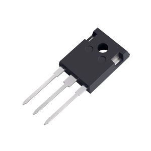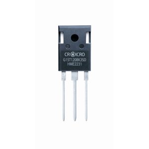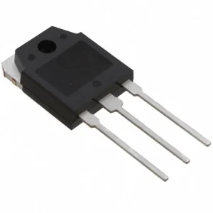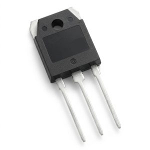

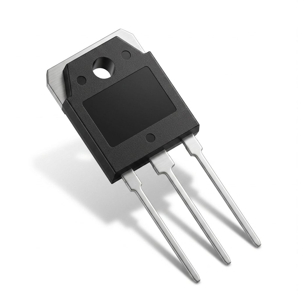
Silan 60N60FD1 Field Stop IGBT with Fast Recovery Diode 600V 60A TO-3P
Silan 60N60FD1: 600V 60A Field Stop IGBT with fast recovery diode in TO-3P. Ideal for induction heating, UPS, SMPS & PFC. Low loss, fast switching.
145.00 EGP
In stockSKU 3496300159451
Buy Now
Shipping across EgyptDelivered to your door
Cash on deliveryPay when your order arrives
Not sure it fits your project?Ask us on WhatsApp - we reply fast
Silan 60N60FD1 Field Stop IGBT with Fast Recovery Diode 600V 60A TO-3P
The 60N60FD1 (SGT60N60FD1PN) from Silan Microelectronics is a 60A, 600V Field Stop IGBT with an integrated fast recovery diode (FRD), supplied in the industry-standard TO-3P 3-pin through-hole package.
Built on Silan’s Field Stop IGBT technology, this device offers optimum performance for induction heating, UPS (uninterruptible power supplies), SMPS (switched-mode power supplies) and PFC (power factor correction) applications. It combines low conduction loss and fast switching with high input impedance, and achieves a typical collector-emitter saturation voltage of just 2.2V at IC = 60A.
Features
- 60A, 600V Field Stop IGBT (N-Channel)
- VCE(sat) (typ.) = 2.2V @ IC = 60A
- Low conduction loss
- Fast switching (recommended frequency 10–60 kHz)
- High input impedance
- Co-packaged fast recovery diode
- High current capability: 120A @ TC = 25°C, 180A pulsed
- Wide junction temperature range: –55°C to +175°C
Specifications
| ABSOLUTE MAXIMUM RATINGS (TC = 25°C unless otherwise noted) | ||||
| Characteristic | Symbol | Test Condition | Rating | Unit |
| Collector to Emitter Voltage | VCE | — | 600 | V |
| Gate to Emitter Voltage | VGE | — | ±20 | V |
| Collector Current | IC | TC = 25°C | 120 | A |
| Collector Current | IC | TC = 100°C | 60 | A |
| Pulsed Collector Current | ICM | — | 180 | A |
| Maximum Power Dissipation | PD | TC = 25°C | 321 | W |
| Operating Junction Temperature | TJ | — | -55 ~ +175 | °C |
| Storage Temperature Range | Tstg | — | -55 ~ +175 | °C |
| THERMAL CHARACTERISTICS (TO-3P) | ||||
| Thermal Resistance, Junction to Case (IGBT) | RθJC | — | 0.39 | °C/W |
| Thermal Resistance, Junction to Case (FRD) | RθJC | — | 1.10 | °C/W |
| Thermal Resistance, Junction to Ambient | RθJA | — | 40 | °C/W |
| ELECTRICAL CHARACTERISTICS – IGBT (TC = 25°C unless otherwise noted) | ||||
| Characteristic | Symbol | Test Condition | Min. / Typ. / Max. | Unit |
| Collector to Emitter Breakdown Voltage | BVCE | VGE = 0V, IC = 250µA | 600 / – / – | V |
| C-E Leakage Current | ICES | VCE = 600V, VGE = 0V | – / – / 200 | µA |
| G-E Leakage Current | IGES | VGE = 20V, VCE = 0V | – / – / ±400 | nA |
| G-E Threshold Voltage | VGE(th) | IC = 250µA, VCE = VGE | 4.0 / 5.0 / 6.5 | V |
| Collector to Emitter Saturation Voltage | VCE(sat) | IC = 60A, VGE = 15V | – / 2.2 / 2.7 | V |
| Collector to Emitter Saturation Voltage | VCE(sat) | IC = 60A, VGE = 15V, TC = 125°C | – / 2.6 / – | V |
| Input Capacitance | Cies | VCE = 30V, VGE = 0V, f = 1MHz | – / 2850 / – | pF |
| Output Capacitance | Coes | – / 294 / – | pF | |
| Reverse Transfer Capacitance | Cres | – / 85 / – | pF | |
| Turn-On Delay Time | Td(on) | VCE = 400V, IC = 60A, Rg = 10Ω, VGE = 15V, Inductive Load | – / 36 / – | ns |
| Rise Time | Tr | – / 142 / – | ns | |
| Turn-Off Delay Time | Td(off) | – / 193 / – | ns | |
| Fall Time | Tf | – / 136 / – | ns | |
| Turn-On Switching Loss | Eon | VCE = 400V, IC = 60A, Rg = 10Ω, VGE = 15V, Inductive Load | – / 3.72 / – | mJ |
| Turn-Off Switching Loss | Eoff | – / 1.77 / – | mJ | |
| Total Switching Loss | Est | – / 5.49 / – | mJ | |
| Total Gate Charge | Qg | VCE = 400V, IC = 60A, VGE = 15V | – / 179 / – | nC |
| Gate to Emitter Charge | Qge | – / 23 / – | nC | |
| Gate to Collector Charge | Qgc | – / 100 / – | nC | |
| ELECTRICAL CHARACTERISTICS – FRD (TC = 25°C unless otherwise noted) | ||||
| Characteristic | Symbol | Test Condition | Min. / Typ. / Max. | Unit |
| Diode Forward Voltage | VFM | IF = 30A, TC = 25°C | – / 1.9 / 2.6 | V |
| Diode Forward Voltage | VFM | IF = 30A, TC = 125°C | – / 1.5 / – | V |
| Diode Reverse Recovery Time | Trr | IES = 30A, dIES/dt = 200A/µs | – / 38 / – | ns |
| Diode Reverse Recovery Charge | Qrr | IES = 30A, dIES/dt = 200A/µs | – / 85 / – | nC |

Applications
- Induction Heating
- Uninterruptible Power Supplies (UPS)
- Switched-Mode Power Supplies (SMPS)
- Power Factor Correction (PFC)
Package Content
- 1 x Silan 60N60FD1 Field Stop IGBT with Fast Recovery Diode 600V 60A TO-3P
DataSheet
Related products