The MAX7219 is compact, serial input/output common-cathode display drivers that interface microprocessors to 7-segment numeric LED displays of up to 8 digits or 64 individual LEDs. It includes an on-chip BCD code-B decoder, multiplex scan circuitry, segment and digits drivers, and an 8×8 static RAM that stores each digit. Only one external resistor is required to set the segment current for all LEDs.
Features
- MAX7219 Driver Board
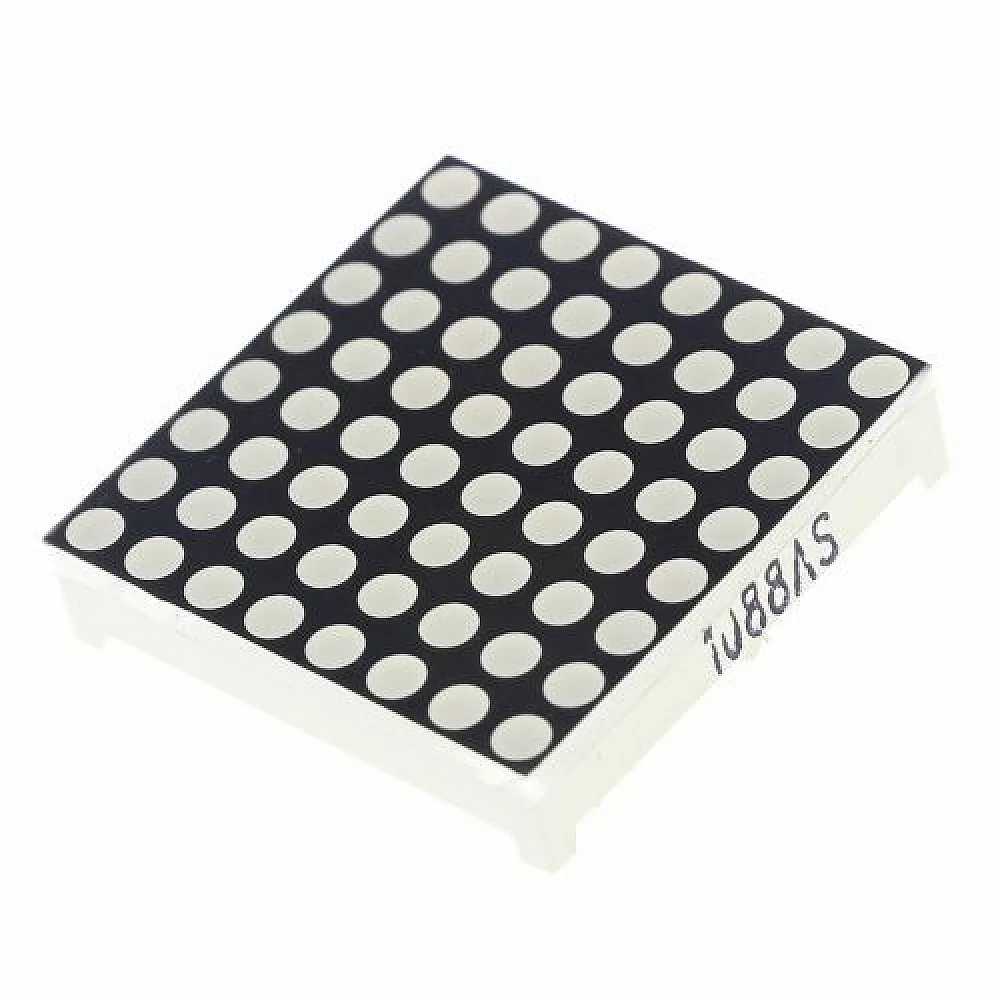
- A single module can drive an 8*8 common cathode matrix
- Module with input and output interface, supporting multiple module cascade
- 4 fixing screw holes, 3mm aperture , can be fixed with M3 copper column
Specifications
- Input Voltage: 3.7 to 5.3 V
- Input Current: 320 mA
- Dimensions:3.2cm X 3.2cm X1.5cm
Application
- Bar-Graph Displays
- 7-Segment Displays
- Industrial Controllers
- Electronic Panel Meters
- LED Matrix Displays
- Display of symbols, simple graphics and texts.
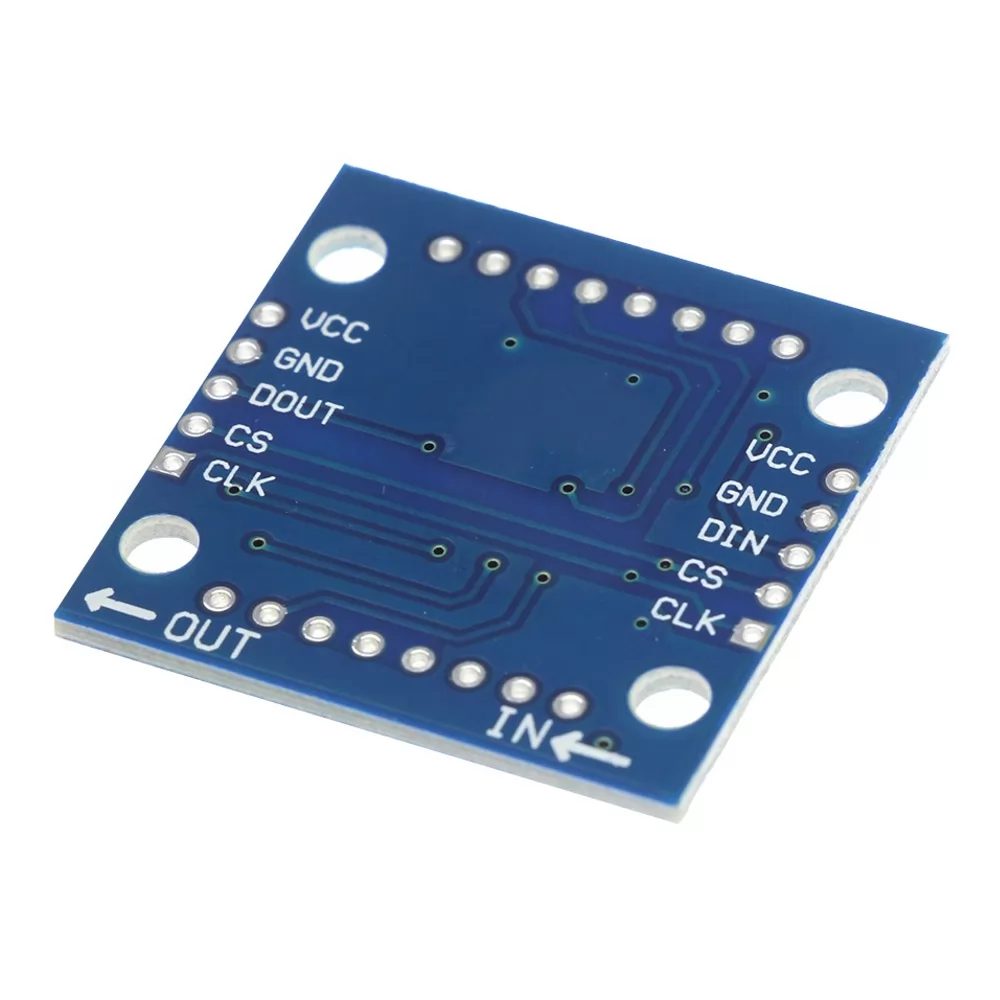
Input Connector
The header pins on the “IN” side is the main input connector. “Vcc” connects to 5V. Due to the fairly high current draw of the display (up to 250mA if the brightness is cranked all the way up), it is recommended to keep the brightness turned down to < 50% to avoid overheating the MCU voltage regulator if there are other peripherals also attached to this supply. “GND” connects to ground which needs to be common with the MCU.
The other pins are for the SPI interface. “DIN” is the Data In. “CS” is Chip Select (sometimes labeled as LOAD) and “CLK is the Clock pin. These lasts 3 pins are connected to any digital outputs on the microcontroller. Which pins they connect to is defined when an instance of the LedControl is created as shown in the program below.
1 x 5 Header
- VCC – Connect to 5V.
- GND – Connect to system ground. This ground needs to be in common with the MCU.
- DIN – Connect to any digital pin on MCU.
- CS / LOAD – Connect to any digital pin on <CU.
- CLK – Connect to any digital pin on MCU.
Output Connector
The break-out pins on the other end of the assembly are used if it is desirable to daisy-chain multiple displays. In this case, the “DOUT” is Data Out and it connects to the next modules “DIN” Data in pin. The other pins are passed straight-thru
1 x 5 Header
- VCC – Connect to 5V on next module if looping power through.
- GND – Connect to GND on next module
- DOUT – Connect to DIN on next module.
- CS / LOAD – Connect to CS / LOAD on next module
- CLK – Connect to CLK on next module
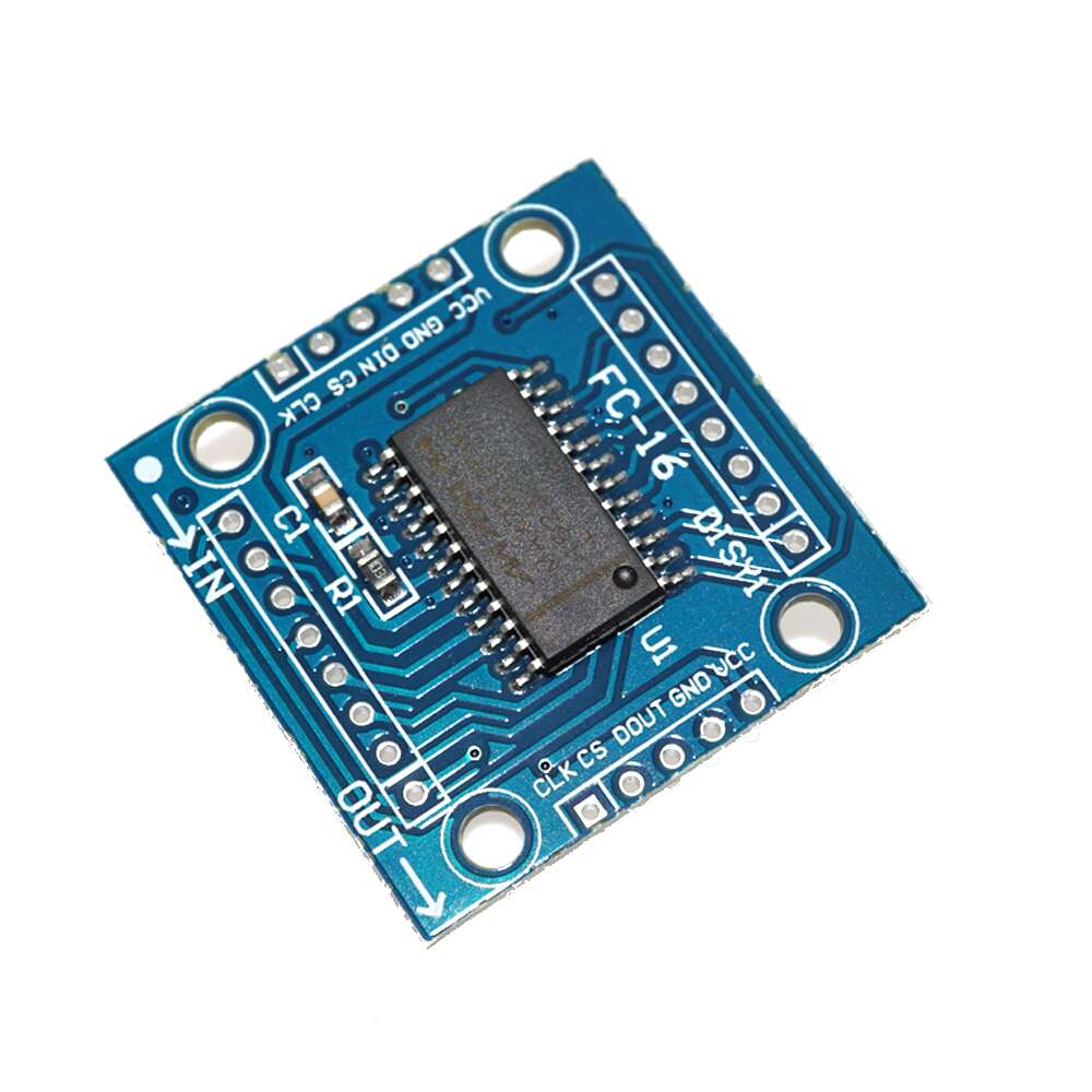
ASSEMBLING MODULE
This comes as a kit that requires some soldering in order to complete, but all the hard stuff is already done such as mounting the MAX7219 IC and other surface mounted devices.
The kit may come with a right-angle header and a straight header or it may come with two right-angle headers.
When assembling the module, follow these basic steps:
- Install and solder one of the headers into the input (‘IN’) side of the board.
- Use a right angle header mounted on the MAX7219 chip side (top) of the board. The header can also be mounted on the bottom side if desired. The module can be mounted vertically in a solderless breadboard.
- If it comes with a straight header or have some on-hand, you can optionally mount this on the bottom side so that it can be laid flat on a solderless breadboard.
- If you are going to use the daisy-chain feature, install a right angle header on the end of the board marked ‘OUT‘.
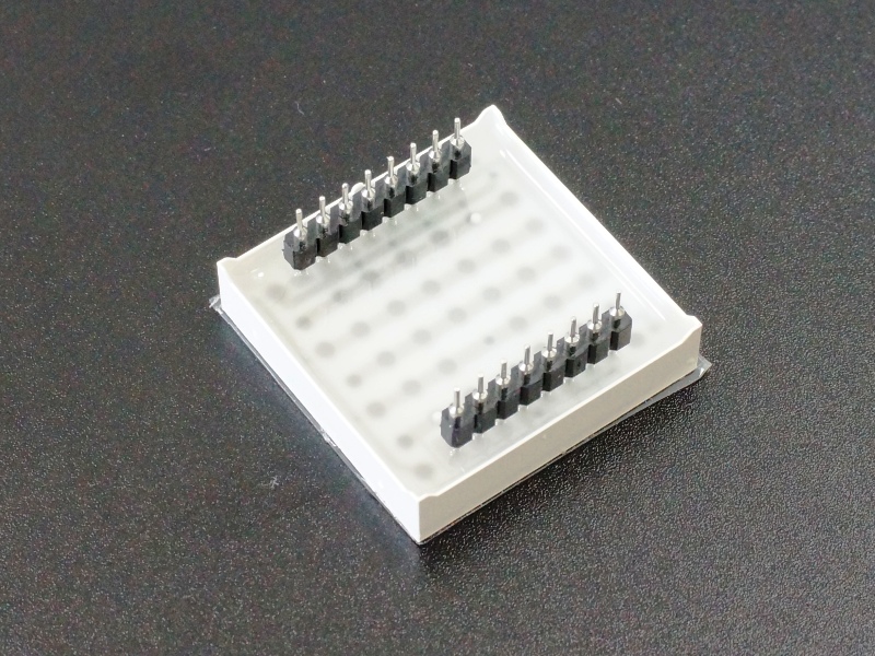
- Next place the LED array face down and install the 2 rows of female sockets onto the pins of the LED module as shown. This is to keep everything nicely aligned during soldering.

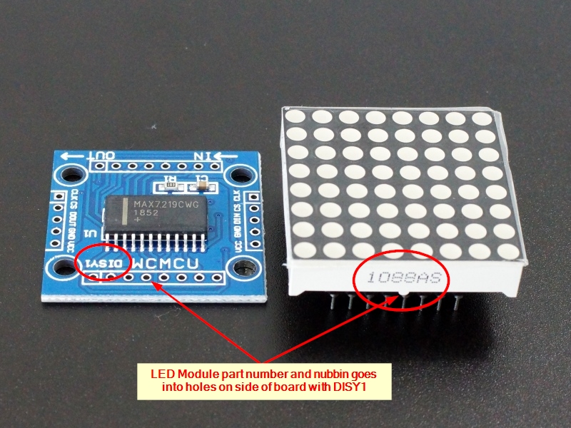
- Insert the LED array into the board on the same side of the PCB as the MAX7219 chip (top side). To orient the module correctly, refer to the picture that shows how the printing on the side of the LED module and little nubbin hanging down should line up with the side of the board that has ‘DISY1‘ printed on it which is opposite the IN/OUT markings.
- Turn the module over and solder all the module pins.
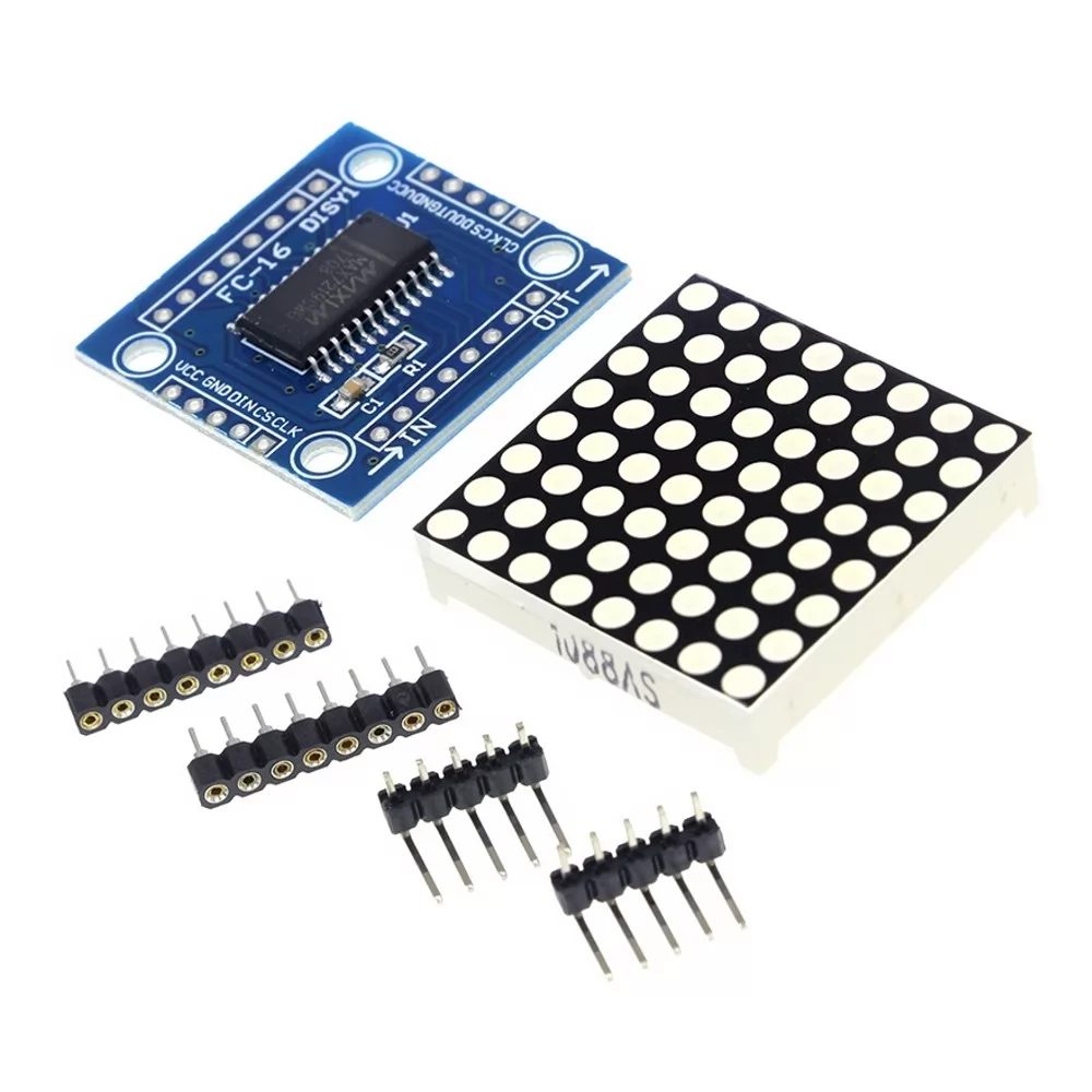
PACKAGE INCLUDES
- 1.3″ 8 x 8 dot matrix of red LEDs
- MAX7219 LED Driver board
- 8-pin female socket (x2)
- 5-pin right-angle male header
- 5-pin straight male header
For arduino projects, check this version.