MAX807LCPE Microprocessor Supervisory Circuit With Precision 4.675V Voltage Monitoring 20mA/250mA DIP-16
MAX807LCPE microprocessor supervisory circuit with ±1.5% reset accuracy: 4.675V threshold, watchdog timer, battery backup, 250mA output, 16-pin DIP.
250.00 EGP
In stockSKU 3496300159697
Buy Now
Shipping across EgyptDelivered to your door
Cash on deliveryPay when your order arrives
Not sure it fits your project?Ask us on WhatsApp - we reply fast
MAX807LCPE Microprocessor Supervisory Circuit With Precision 4.675V Voltage Monitoring 20mA/250mA DIP-16
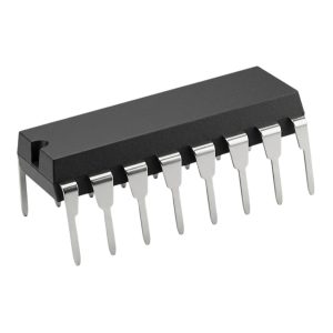
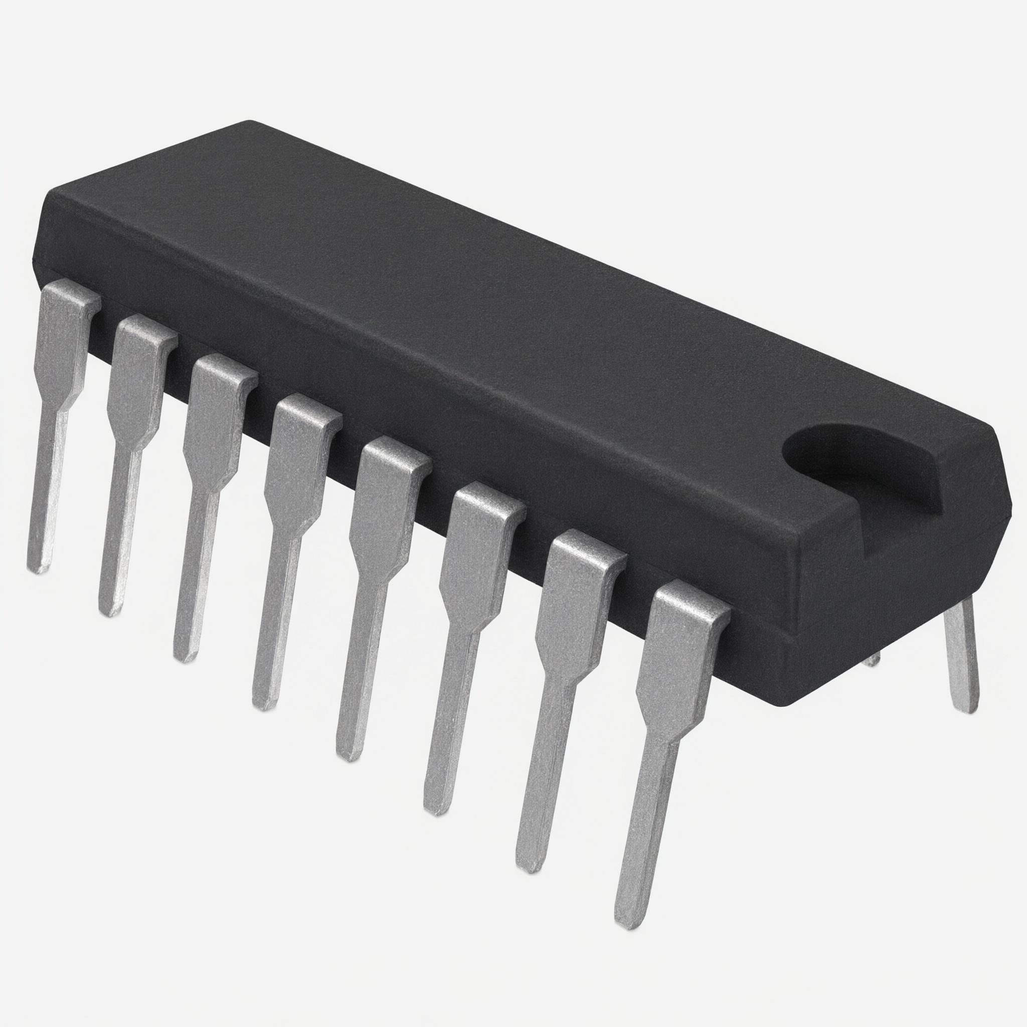
The MAX807LCPE from Maxim Integrated Products is a full-featured microprocessor (µP) supervisory circuit built with BiCMOS technology for improved ±1.5% reset-threshold precision. It is the MAX807L version, featuring a precision 4.675V reset threshold, housed in a 16-pin Plastic DIP (PDIP) package and specified for operation from 0°C to +70°C from a nominal +5V supply.
The MAX807 reduces the complexity and number of components needed to monitor power-supply and battery-control functions in µP systems. A 70µA supply current makes it ideal for use in portable equipment, while a 2ns chip-enable propagation delay and 250mA output current capability (20mA in battery-backup mode) make it suitable for larger, higher-performance equipment.
Features
- Precision 4.675V voltage monitoring (MAX807L version), ±1.5% reset accuracy
- 200ms power-OK/reset time delay
- RESET and RESET outputs (active-low and active-high)
- RESET output guaranteed valid down to VCC = 1V
- Manual-reset input (active-low, internal pullup, no debounce needed)
- Independent watchdog timer (1.6s typ timeout)
- 1µA standby current in battery-backup mode; 70µA (typ) operating supply current
- Power switching: 250mA in VCC mode, 20mA in battery-backup mode
- Two-stage power-fail warning: low-line threshold 52mV above reset threshold, ±1.5% accuracy
- On-board gating of chip-enable signals with 2ns CE propagation delay (write-protects CMOS RAM/EEPROM)
- Backup-battery switchover and backup-battery monitor (BATT OK flag)
- 2.275V threshold detector for power-fail warning / low-battery detection / monitoring supplies other than +5V
- 16-pin Plastic DIP package, 0°C to +70°C
Specifications
| Parameter | Specification |
|---|---|
| PRODUCT IDENTIFICATION | |
| Part Number | MAX807LCPE |
| Manufacturer | Maxim Integrated Products |
| IC Type | Full-Featured Microprocessor (µP) Supervisory Circuit with ±1.5% Reset Accuracy |
| Reset Threshold Version | L – 4.675V (typical) |
| Package | 16-Pin Plastic DIP (PDIP) |
| Operating Temperature Range | 0°C to +70°C |
| Nominal Supply Voltage (VCC) | +5V (operating range 4.60V to 5.5V for the MAX807L) |
| Datasheet Reference | Maxim 19-0433; Rev 4; 11/05 |
| RESET & LOW-LINE SUPERVISION | |
| Reset Threshold Voltage (VRST), MAX807L | 4.675V typ (4.600V min, 4.750V max); VCC rising and falling |
| Reset Threshold Accuracy | ±1.5% |
| Reset Threshold Hysteresis | 13mV typ |
| LOW LINE to Reset Threshold (VLR) | 52mV typ (30mV min, 70mV max); VCC falling |
| LOW LINE Threshold (VCC rising), MAX807L | 4.73V min to 4.81V max |
| Low-Line Threshold Accuracy | ±1.5%, 52mV above reset threshold |
| Reset Active-Timeout Period (tRP) | 200ms typ (140ms min, 280ms max); VCC rising |
| VCC to RESET Delay | 26µs typ (VCC falling at 1mV/µs) |
| VCC to LOW LINE Delay | 24µs typ (VCC falling at 1mV/µs) |
| RESET Validity | Guaranteed correct (logic low) for VCC down to 1V; maintained for 0V < VCC < VRST with VBATT > 2V |
| WATCHDOG TIMER | |
| Watchdog-Timeout Period (tWD) | 1.6s typ (1.12s min, 2.24s max) |
| Minimum Watchdog Input Pulse Width | 100ns typ |
| WDI Threshold Voltage | VIL = 0.8V max; VIH = 0.75 × VCC min |
| WDI Input Current (reset deasserted) | -10µA typ / -50µA max (WDI = 0V); 16µA typ / 50µA max (WDI = VCC) |
| Watchdog-Fault Output (WDO) | Low if WDI not toggled within tWD; high during reset or when WDI is unconnected; connect WDO to MR to force a reset on each watchdog fault |
| POWER SUPPLY & BATTERY BACKUP | |
| Operating Voltage Range (VBATT, VCC) | 0V to 5.5V (either input can go to 0V if the other is greater than 2.0V) |
| Supply Current, Normal Operating Mode (excl. IOUT) | 70µA typ, 110µA max |
| Supply Current, Battery-Backup Mode (excl. IOUT) | 0.4µA typ, 1µA max (VCC = 0V, VBATT = 2.8V) |
| BATT Standby Current (normal mode) | ±0.1µA typ, ±1.0µA max (VBATT = 2.8V, VCC = 3.0V) |
| Output Current Capability | 250mA in VCC mode; 20mA in battery-backup mode |
| VCC-to-OUT On-Resistance | 1.0 to 1.2Ω typ (1.4 to 2.5Ω max, depending on VCC / IOUT) |
| BATT-to-OUT On-Resistance | 16Ω typ (VBATT = 2.0V, IOUT = 5mA); 12Ω typ (VBATT = 2.8V, IOUT = 10mA); 8.5Ω typ (VBATT = 4.5V, IOUT = 20mA) |
| VOUT, Normal Operating Mode | VCC – 0.02V typ (IOUT = 25mA); typically 260mV below VCC at the maximum 250mA output current |
| VOUT, Battery-Backup Mode | VBATT – 0.08V typ (VBATT = 2.0V, IOUT = 5mA); VBATT – 0.12V typ (VBATT = 2.8V, IOUT = 10mA); VBATT – 0.17V typ (VBATT = 4.5V, IOUT = 20mA) |
| Battery-Switchover Threshold | VBATT typ (power-down); VBATT + 0.05V typ (power-up) |
| Battery-Switchover Hysteresis | 50mV typ |
| Switchover Conditions | VCC below reset threshold AND VCC below VBATT |
| Battery Switch Topology | OUT connects to BATT through two internal series PMOS switches (facilitates UL approval) |
| Backup Source Compatibility | MaxCap®, SuperCap® (e.g., 0.47F) and conventional batteries; VBATT may exceed VCC |
| BATT ON Output | High: 2.0V min / 2.7V typ (VCC = 0V, ISOURCE = 0.1mA, VBATT = 2.8V); Low: 0.4V max (ISINK = 3.2mA); drives an external PNP/PMOS pass transistor for IOUT above 250mA |
| CHIP-ENABLE (CE) GATING – RAM WRITE PROTECTION | |
| CE IN to CE OUT Propagation Delay | 2ns typ, 8ns max (VCC = 5V, CLOAD = 50pF, 50Ω driver) |
| CE IN to CE OUT Resistance (enabled mode) | 75Ω typ, 150Ω max |
| CE IN Leakage Current (disabled mode, MR = 0V) | ±1µA max |
| RESET to CE OUT Delay (VCC falling) | 28µs typ |
| CE OUT Output Voltage High (RESET active, disabled) | 3.5V min (VCC = 5V, MR = 0V) |
| CE OUT Short-Circuit Current (RESET active) | 17mA typ (VCC = 5V, CE OUT = 0V, MR = 0V) |
| CE OUT (disabled mode) | Actively pulled up to the higher of VCC or VBATT |
| POWER-FAIL COMPARATOR (PFI / PFO) | |
| PFI Input Threshold (VPFT) | 2.265V typ, input falling (2.200V to 2.330V); 2.285V typ, input rising (2.220V to 2.350V); nominal 2.275V detector |
| PFI Hysteresis | 20mV typ |
| PFI to PFO Delay | 14µs typ (power failing); 32µs typ (power restored) |
| PFI Leakage Current | ±0.005nA typ, ±40nA max |
| PFO Operation | Low when PFI < VPFT; valid for VCC ≥ 4V; external resistor divider allows monitoring of supplies other than +5V |
| MANUAL RESET INPUT (MR) | |
| MR Threshold | VIL = 0.8V max; VIH = 2.4V min |
| MR Pullup Current | 50µA min, 100µA typ, 200µA max (MR = 0V) |
| MR Minimum Pulse Width | 1µs |
| MR-to-RESET Propagation Delay | 170ns typ |
| MR Usage | Active-low with internal pullup; TTL/CMOS compatible; momentary switch to GND (no debounce required); supports diode-OR of multiple reset sources |
| BATTERY-OK COMPARATOR (BATT OK) | |
| BATT OK Threshold (VBOK) | 2.265V typ (2.200V min, 2.350V max) |
| BATT OK Hysteresis | 20mV typ |
| BATT OK Operation | High when VBATT exceeds threshold (backup battery OK); valid for VCC ≥ 4V |
| LOGIC OUTPUTS (RESET, RESET, LOW LINE, WDO, PFO, BATT OK) | |
| Output Low Voltage (VOL) | 0.4V max at ISINK = 3.2mA |
| Output High Voltage (VOH) | VCC – 1.5V min at ISOURCE = 5mA (RESET: VCC – 1.5V min at ISOURCE = 0.1mA, VCC – 0.1V typ) |
| Output Short-Circuit Current (typ) | RESET: 60mA sink / 1.6mA source; RESET: 60mA sink / 15mA source; LOW LINE: 28mA sink / 20mA source; WDO, PFO, BATT OK: 35mA sink / 20mA source |
| RESET Output Structure | Strong pulldown / relatively weak pullup – can be wire-OR connected; RESET (active-high) sources and sinks current – cannot be wire-OR connected |
| ABSOLUTE MAXIMUM RATINGS | |
| Input Voltage VCC, VBATT (w.r.t. GND) | -0.3V to +6V |
| Input Voltage, All Other Inputs | -0.3V to (VOUT + 0.3V) |
| Input Current, VCC | 1.0A peak / 500mA continuous |
| Input Current, IBATT | 250mA peak / 50mA continuous |
| Input Current, GND and All Other Inputs | 50mA |
| Continuous Power Dissipation (16-Pin Plastic DIP, TA = +70°C) | 842mW (derate 10.53mW/°C above +70°C) |
| Operating Temperature Range | 0°C to +70°C |
| Storage Temperature Range | -65°C to +160°C |
| Lead Temperature (soldering, 10s) | +300°C |


Applications
- Computers
- Controllers
- Intelligent Instruments
- Critical µP Power Monitoring
- Portable / Battery-Powered Equipment
Package Content
- 1 x MAX807LCPE Microprocessor Supervisory Circuit With Precision 4.675V Voltage Monitoring 20mA/250mA DIP-16
DataSheet
Related products