


3- Channels Servo Tester – Versatile Tool for Testing and Calibrating Servo Motors
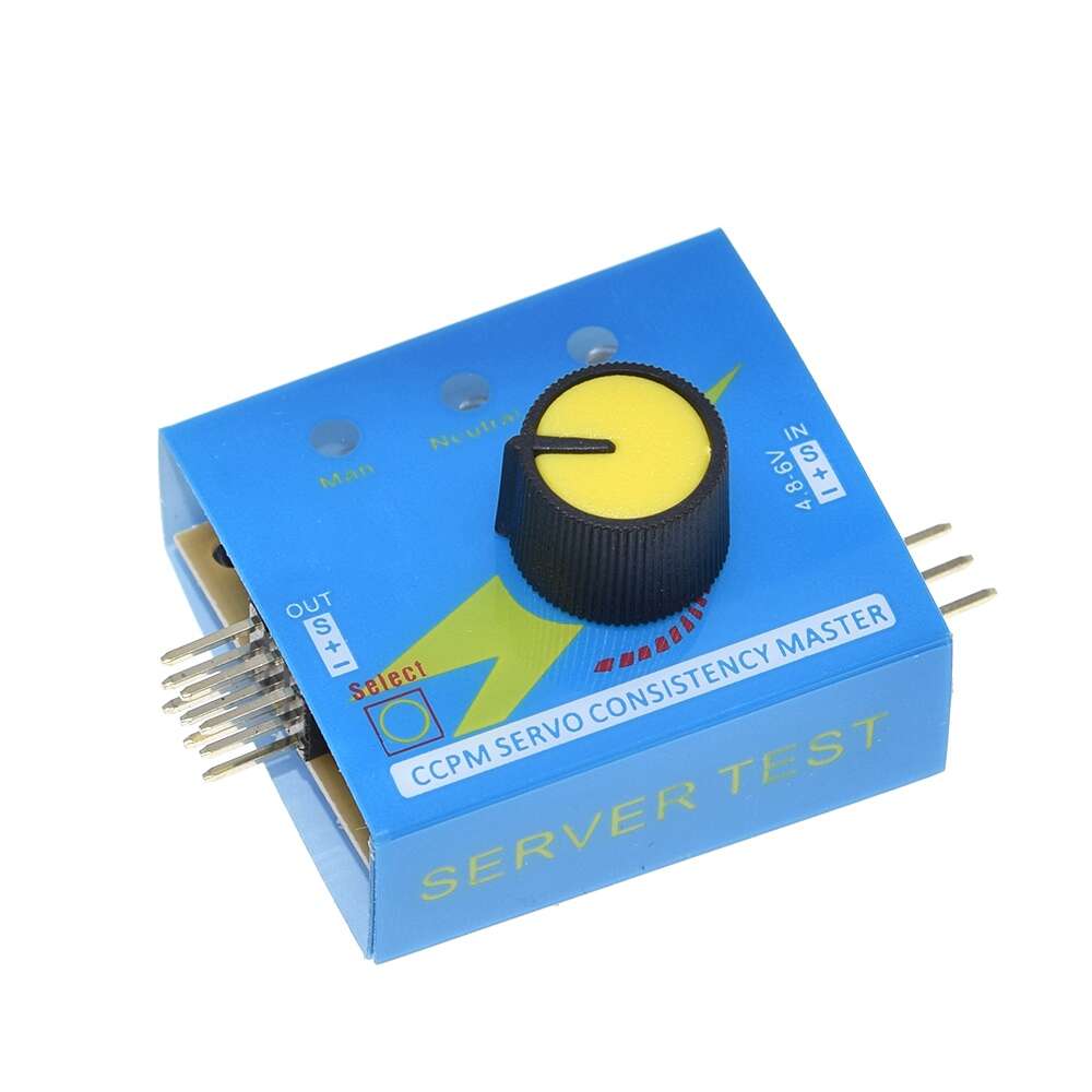
The Servo Tester is a versatile tool designed for testing and calibrating servo motors. It features three operational modes—manual, neutral, and auto—allowing users to control servo positions easily. With the capability to connect up to three servos, it operates on a voltage range of 4.8 to 6V. Ideal for hobbyists and engineers, this compact device simplifies servo testing without the need for complex setups.
Features:
- 3 modes of operation
- Manual position mode using adjustment knob
- Return to center
- Auto sweep back and forth
- Output connectors for up to 3 servos
- Can be used as input for ESC to test operation
- 4.8-6V operation and output pulse amplitude
Specifications:
- Input voltage: 4.8V to 6V
- Housing made of soft plastic
- Three mode selection [Manual, Neutral and Auto]
- Frequency: 49Hz measured (50Hz nominal)
- Output Current: >15 mA (5 mA per berg)
- Mode selection LED Indicator
- Adjustable Knob for manual speed control
- Output signal: 1.5ms±0.5ms
- Dimensions (L x W x H w/out pins) : 35mm x 31mm x 24mm
Theory of Operation:
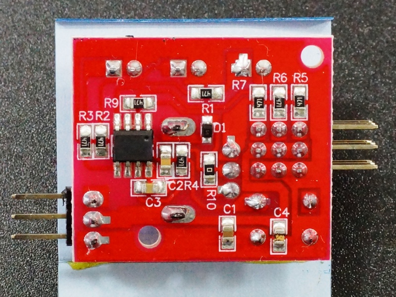 The picture to the right shows what’s inside the servo tester module on the bottom side of the board so you’re not tempted to rip the enclosure off to see what is inside.
The 8-pin IC appears to be a microcontroller with the markings removed. There are a bunch of 470Ω resistors for providing current limiting for the three LEDs as well as the three PWM outputs. The PWM outputs each have their own current limiting resistor, but they are all driven off the same signal.
The power and ground pins on the input side pass straight through to the power and ground pins on the servo connectors with a few filtering caps thrown in. Since the servos operate at 4.8 to 6V, the input needs to be fed with a power source between 4.8V and 6V.
Inputs:
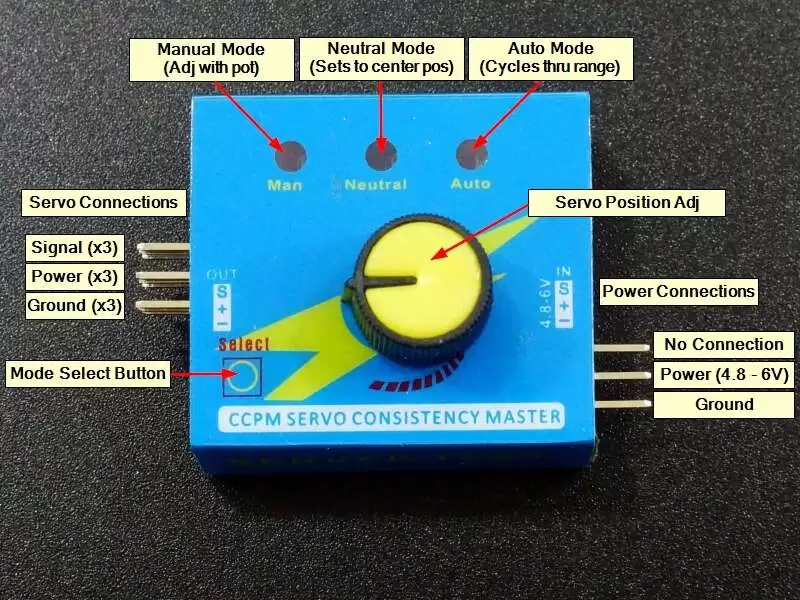
The input side is a 3-pin male header. Power is connected to ‘+‘ and ground is connected to ‘–‘. Current draw from the power supply will depend on the servo(s) being driven.
The ‘S’ (signal) pin on the input side is not connected to anything and can be left unconnected.
Outputs:
The output is a 3×3 male header.
Up to 3 servos can be connected by plugging the connectors in horizontally across the row of 3 pins. The servo brown (ground) wire goes to ‘–‘, the servo red (power) wire goes to ‘+‘ and the servo yellow/orange (signal) wire goes ‘S‘.
Modes of Operation:
There are 3 modes of operation for the servo tester. The blue LEDs indicate the currently active mode and the SELECT button toggles between the different modes. When the device first powers up, the Manual mode is selected.
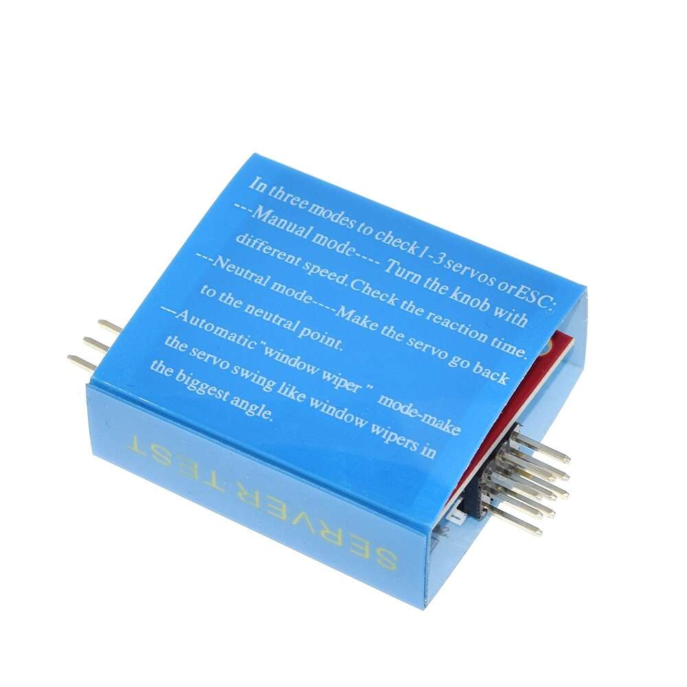
- MAN – Manual Mode. Turning the knob controls the position of the servo. This is handy for testing the functionality of the servo in an application without having to setup an MCU with software. If a servo is connected to the elbow of a mechanical arm, the arm can be exercised through its range using the control knob.
- NEUTRAL – Returns the servo to the center position.
- AUTO – Runs the servo continuously through its full range left and right approximately once per second. This can be handy for testing servos over time or to automate the movement of a device such as a prop that needs to swing back and forth.
Note: This device is only designed to work with servos or as a PWM input to an ECS (Electronic Speed Control) unit. It is designed to drive a low current PWM output and simply pass power and ground through. It is not suitable to try to control DC motors directly using PWM as it cannot provide the necessary current.