


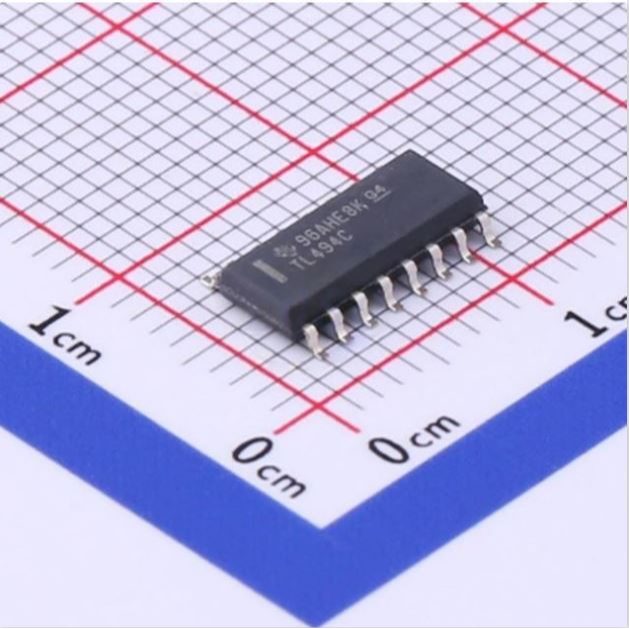
TL494C 7V~40V PWM SMD IC SOIC-16-150mil
The TL494C is a versatile pulse-width-modulation (PWM) control circuit integrated circuit designed by Texas Instruments for efficient power-supply control. This device incorporates all essential functions required for constructing PWM control circuits on a single chip, offering flexibility to tailor power-supply control to specific applications. It features two error amplifiers, an adjustable on-chip oscillator, a dead-time control comparator, a pulse-steering flip-flop, a precision 5V regulator with 5% tolerance, and output-control circuits.
Features:
- Complete PWM Power-Control Circuitry.
- Uncommitted Outputs for 200-mA Sink or
Source Current. - Output Control Selects Single-Ended or
Push-Pull Operation. - Internal Circuitry Prohibits Double Pulse at
Either Output. - Variable Dead Time Provides Control Over
Total Range. - Internal Regulator Provides a Stable 5-V Reference Supply With 5% Tolerance.
- Circuit Architecture Allows Easy Synchronization.
Specifications:
| Parameter | Value |
|---|---|
| Supply Voltage Range | 7Vto40V |
| Absolute Maximum Supply Voltage | 41V |
| Oscillator Frequency | 1kHzto300kHz |
| Reference Output Voltage | 4.75Vto5.25V |
| Error Amplifier Open-Loop Gain | 70dBto95dB |
| Collector Output Voltage | 40V |
| Collector Output Current | 200mA |
| Propagation Delay | 400ns |
| Operating Temperature Range | 0°Cto70°C |
| Package Type | SOIC-16-150mil |
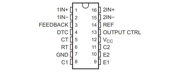
Pin Configuration:
| PIN | TYPE | DESCRIPTION | |
|---|---|---|---|
| NAME | NO. | ||
| 1IN+ | 1 | I | Noninverting input to error amplifier 1 |
| 1IN- | 2 | I | Inverting input to error amplifier 1 |
| 2IN+ | 16 | I | Noninverting input to error amplifier 2 |
| 2IN- | 15 | I | Inverting input to error amplifier 2 |
| C1 | 8 | O | Collector terminal of BJT output 1 |
| C2 | 11 | O | Collector terminal of BJT output 2 |
| CT | 5 | — | Capacitor terminal used to set oscillator frequency |
| DTC | 4 | I | Dead-time control comparator input |
| E1 | 9 | O | Emitter terminal of BJT output 1 |
| E2 | 10 | O | Emitter terminal of BJT output 2 |
| FEEDBACK | 3 | I | Input pin for feedback |
| GND | 7 | — | Ground |
| OUTPUT CTRL | 13 | I | Selects single-ended/parallel output or push-pull operation |
| REF | 14 | O | 5-V reference regulator output |
| RT | 6 | — | Resistor terminal used to set oscillator frequency |
| VCC | 12 | — | Positive Supply |
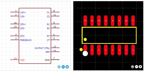
Foot Print:
Applications:
- Desktop PCs.
- Microwave Ovens.
- Power Supplies: AC/DC, Isolated, With or Without PFC
- Server PSUs.
- Solar Micro-Inverters.
- Washing Machines: Low-End and High-End
- E-Bikes.
- Power: Telecom/Server AC/DC Supplies:
Dual Controller: Analog - Smoke Detectors.
- Solar Power Inverters.


