

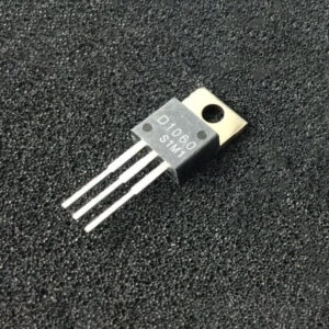
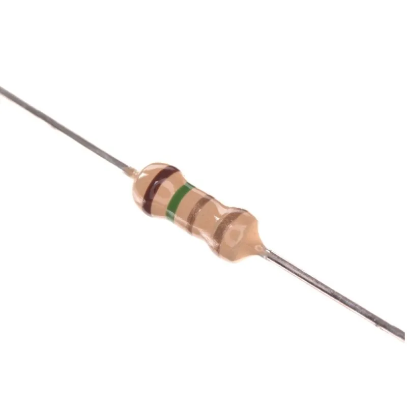

Lithium-Ion Battery Charger BMS Protection Board Modules

Lithium-Ion Battery Charger BMS Protection Board Modules
Content List
- Introduction.
- What is the BMS Battery Management System?
- Why Do We Need a Battery Management System (BMS)?
- How Does Battery Management System (BMS) Work?
- Basic Protection Functions.
- Basic Types of Protection Board Modules.
- Difference Between PCM and BMS.
- Which to choose: a PCM or a BMS?
- Main Functions of a Lithium Battery BMS Protection Board Module.
- Common Types of BMS Protection Boards.
- Construction of a Lithium-Ion Charger BMS Protection Board Module.
- Theory of Operation for Battery Charger BMS Protection Board Module.
- How to Choose the Right (BMS) System.
- Common Problems.
- Safety Tips.
- Applications.
- Frequently Asked Questions (FAQs).
- Helpful Resources.
- Conclusion.
Reading Time 15 minute
Introduction
- Lithium battery protection boards act as mandatory safety guardians, blocking overcharge, over-discharge, short circuits and extreme temperatures to avoid thermal runaway and fire hazards.
- Core hardware including protection ICs, MOSFET switches, resistors and temperature sensors continuously monitor voltage, current and temperature with millisecond-fast cutoff responses.
- Three distinct solutions exist: PCB (circuit substrate), low-cost single-cell PCM, and full-featured intelligent BMS for multi-series large battery packs.
- Running lithium cells without proper protection permanently ruins capacity, cuts cycle life by 50%+, and creates critical fire risks for EVs, drones, power stations and consumer devices.
- Next-generation protection systems integrate AI fault prediction and wireless IoT monitoring to deliver proactive, cloud-connected battery health management.
- Always use certified UL/UN38.3 compliant PCM/BMS boards matched to your battery’s cell count, current rating and chemistry.
What is the Battery Management System BMS ?
A battery management system (BMS) refers to an electronic system responsible for overseeing the operations of a rechargeable battery, whether it is an individual cell or a battery pack. The BMS performs various functions, including safeguarding the battery from operating beyond its safe range, monitoring its current state, generating additional data, reporting that data, controlling the battery’s environment, authenticating it, and ensuring its balance.
People mainly use BMS in large-scale battery systems and can apply it in automobiles and energy storage. The primary function of BMS is to control battery packs, performing tasks like safety protection, charging and discharging management, and information monitoring.
Why Do We Need a Battery Management System (BMS) ?
The importance of BMS becomes obvious when it comes to electric vehicles. The BMS serves as a link between the battery and the vehicle. It deals with complex signals such as battery cell voltage, collision, CAN, charging, water pump, high voltage, insulation, and so on. Overcharging a battery once might result in irreversible damage. Severe instances can cause lithium-ion batteries to overheat or overcharge, resulting in thermal runaway, battery rupture, or even explosion.
To avoid overcharging, over-discharging, and overheating, BMS must rigorously control charging and discharging. The primary power source for electric cars is lithium-ion batteries. Maintaining quality during lithium-ion battery mass production can be difficult, and inconsistent performance can lower lifespan and efficiency. Safety problems like fire and explosion can occur as a consequence of excessive charging or discharging.
Using BMS, you may carefully assess the battery pack’s utilization state, safeguarding it from overcharging and over-discharging. BMS balances battery pack charging levels, calculates charging levels, and turns them into understandable scope information. This assures safe functioning and increases the battery’s longevity.
How Does BMS Battery Management System Work?
The Battery Management System (BMS) consists of a computer that is connected to multiple sensors. These sensors are responsible for observing and measuring the voltage, current, and temperature of every cell, and they transmit this data to the BMS.
After receiving the data, the Battery Management System evaluates the information to guarantee that every cell functions within the specified boundaries. If any cell exceeds these limits, the BMS makes efforts to resolve the issue and rectify the problem.
In the event that the cells within the battery pack reach elevated temperatures, the BMS takes charge of regulating the cooling system to lower the overall temperature of the battery pack.
In case of variations in cell voltage, the Battery Management System performs cell balancing. In order to equalize the voltage levels across all cells, the Battery Management System (BMS) facilitates the transfer of energy from one cell to another. This process aims to maintain a consistent voltage level among all the cells.

Basic Protection Functions
1- Overcharge Protection to Stop Thermal Runaway Risks
Overcharging is one of the top triggers for lithium battery swelling, electrolyte decomposition and thermal runaway. When cells absorb excess voltage beyond their rated maximum, lithium metal plates form on the anode, flammable gas accumulates inside the pouch/casing, and internal heat builds rapidly.
The protection IC enforces a hard upper voltage limit during charging. Once triggered, it blocks further power input until cell voltage drops back to normal. This simple safeguard drastically reduces long-term cell degradation and eliminates the risk of fire from sustained overcharging.
2- Over-Discharge Protection to Prevent Permanent Cell Damage
Deep discharge below the minimum safe voltage permanently ruins lithium cell structure. Draining cells to near-zero voltage strips usable lithium ions from the graphite anode, creating irreversible capacity loss that cannot be restored by recharging.
The protection board monitors voltage during every discharge cycle and disconnects the external load once the low-voltage threshold is hit. This feature is especially vital for seasonal gear like e-bikes and drones that may sit idle for months, as it prevents self-discharge from draining cells to dangerous levels.
3- Instant Short-Circuit & Overcurrent Cutoff Protection
Short circuits happen when positive and negative battery terminals make unintended contact, or internal cell damage creates conductive leakage paths. This generates extreme instantaneous current that spikes internal temperatures in seconds.
MOSFET switches on the protection board detect abnormal current surges within microseconds and fully break the circuit. This rapid response avoids melted wiring, cell rupture and flame propagation across multi-cell packs, a mandatory safety feature for high-discharge RC, drone and power tool batteries.
4- Full-Range Thermal Temperature Protection
Lithium cells operate within a narrow safe temperature window; extreme heat or cold both accelerate chemical breakdown and safety hazards. Industry standard thermal limits for lithium-ion:
| Operating Condition | Safe Temperature Range | Risk of Exceeding Limits |
|---|---|---|
| Optimal Long-Term Performance | 15°C – 35°C (59°F – 95°F) | Balanced cycle life and consistent energy output |
| Max Safe Discharge Temperature | Below 45°C (113°F) | Above this threshold accelerates electrolyte breakdown and SEI layer overgrowth |
| Min Safe Discharge Temperature | Above 0°C (32°F) | Cold temperatures raise internal resistance and crack electrode materials |
| Critical Thermal Runaway Threshold | Above 90°C | High risk of separator melting and cascading cell failure |
Built-in thermistors feed real-time temperature data to the protection IC. If readings rise or fall outside approved ranges, the board cuts all power flow to cool the cell stack and prevent thermal runaway.
Basic Types of Protection Board Modules
- PCB (Protection Circuit Board):Basic hardware-only board focused on voltage and current cutoff. It detects overcharge, over-discharge, over-current, and short-circuit, then isolates the pack via MOSFETs. Minimal or no balancing; fixed thresholds; low cost and simple. Suitable for single-cell or very basic packs.
- PCM (Protection Circuit Module):An enhanced PCB that usually adds passive cell balancing (via resistors) for multi-cell packs. Provides the core protections plus basic equalization to keep cell voltages uniform. Still primarily analog/hardware-based with fixed or limited adjustable thresholds. Common for small-to-medium consumer packs.
- BMS (Battery Management System):Advanced intelligent module. Includes all PCM protections plus active or passive balancing, temperature monitoring (often multi-point), state-of-charge (SOC)/state-of-health (SOH) estimation, diagnostics, data logging, and communication interfaces (I²C, SMBus, CAN, UART, Bluetooth, etc.). Often uses a microcontroller + analog front-end (AFE). Essential for larger, high-performance, or safety-critical packs (e.g., e-bikes, EVs, energy storage).
Classification by Protection Level
- Basic Protection Modules
- Overcharge protection
- Over-discharge protection
- Overcurrent protection
- Short-circuit protection
- Intermediate Protection Modules
- Reverse polarity protection
- Overvoltage protection
- Undervoltage protection
- Temperature protection
- Advanced Protection Modules
- Cell balancing modules
- Protection Circuit Modules (PCM)
- Battery Management Systems (BMS)
In practice, most modern battery charger protection boards integrate several of these protection functions into a single module to ensure safe charging, safe discharging, and longer battery life.
Difference Between Battery Charger PCM and BMS Protection
Both PCM and BMS are the most essential parts of a lithium battery, and it would be dangerous if the battery does not have them. Next is the introduction to PCM and BMS, and a contrast between them.
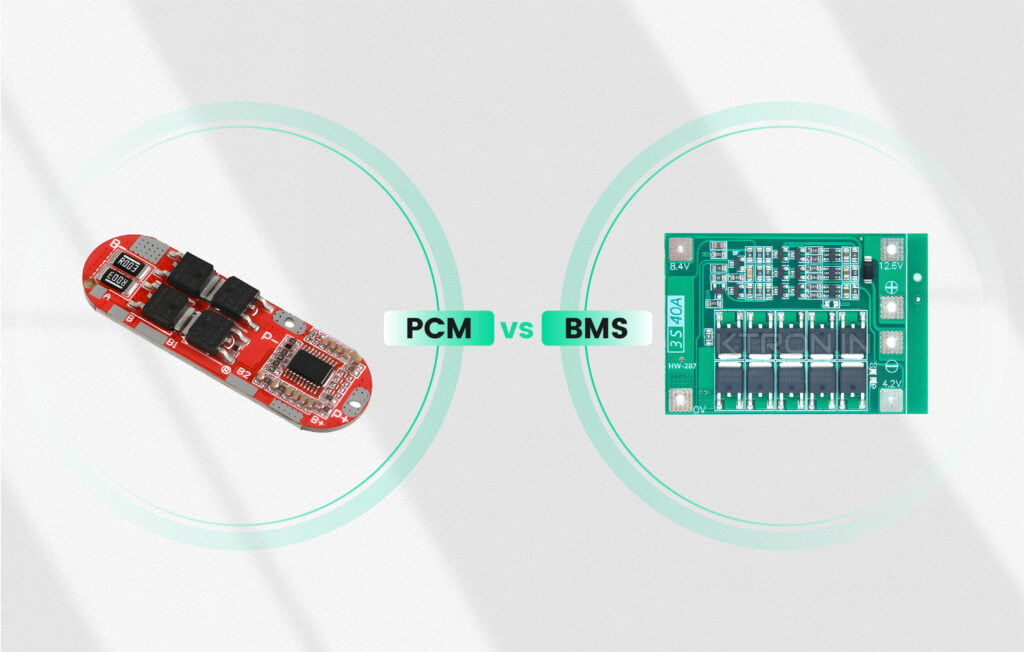
Protection Circuit Module(PCM)
- A PMC is a stand-alone protective circuit.
- It is purely analogical, this means there is no software integrated into it.
- There is no possibility to switch-on or to switch-off the battery pack.
- There is no possibility to get a precise status update about the charging level of the battery pack.
- It cannot steer a charging unit or a consuming unit (electric motor, etc.).
- A PCM only rarely surveys the temperature level.
- It equalizes only in a very basic manner the different elements of an application.
- It is usually a low-cost product, produced in Asia.
Typical applications which make use a PCM: low-cost products like certain electrically assisted bikes or small electric tools.
Battery Management System (BMS) Module
- A BMS is an electronic board which is a lot more advanced than a PCM. A BMS contains a microcontroller with intelligent software integrated into it.
- It calculates and interprets different types of measurements like the SOC (state of charge) or the SOH (state of health).
- It offers a different level of protection (for example: it can distinguish between a normal and an abnormal event with regard to time).
- It contains a communication bus (I2C, CAN, MODBUS, …), allowing for the transfer of information.
- It has the facility of being steered by a main application.
- It has the capability to communicate with other BMS in order to form a battery of much larger capacity, whereby it adapts itself automatically to the different needs.
- It can go into standby mode in order to optimize its energy consumption.
- A BMS possesses an intelligent algorithm to equalize the different elements of an application.
- Via its communication bus, a BMS can steer chargers and/or consuming units (usually a motor) in order to optimize the utilization of the batteries and the behavior of the system.
- It offers the possibility to execute a complete diagnosis of the battery at any given moment.
- It can keep record of the battery life (counting errors, counting usage and storage time,)
Typical applications which make use a BMS: advanced products like robots, drones, electric bikes, electric vehicles, etc.
Technical Specifications Comparison
| Parameter | PCM (Protection Circuit Module) | BMS (Battery Management System) |
| Protection Functions | Overcharge, over-discharge, overcurrent, and short-circuit protection | Complete protection suite with advanced monitoring and thermal management |
| Thermal Monitoring | Limited or no temperature sensing capability | Integrated temperature sensors with active thermal management |
| Communication Interface | No communication protocol support | CAN bus, SMBus, I2C protocol support for system integration |
| Cell Balancing | No balancing functionality | Active cell balancing with individual cell monitoring |
| Power Management | Continuous current draw during operation | Intelligent power management with 50μA standby consumption |
| Monitoring Capabilities | Basic voltage threshold detection | SOC, SOH determination, and comprehensive fault diagnostics |
| Target Applications | – Single-cell portable devices – Power bank applications – Basic handheld electronics – Cost-sensitive products |
– Electric vehicle systems – Industrial battery applications – E-mobility platforms – Unmanned aerial vehicles – High-performance systems |
| Economic Considerations | Lower initial investment cost | Higher development cost with superior long-term value |
| Energy Efficiency | Approximately 85% system efficiency | Up to 95% efficiency through optimized management |
| Implementation Complexity | Minimal integration requirements | Sophisticated configuration and programming requirements |
| Standards Compliance | Basic electrical safety standards | Advanced safety certifications (IEC 61508, ISO26262) |
In a word, both PCM and BMS are to protect the battery, but BMS is more sophisticated than PCM.
The numerous security and performance problems of PCM
The risk of overheating the battery pack, Even though PCMs can be sufficient for certain small devices, the fact that they do not measure the temperature level of the cells can lead to serious problems. If a potential problem has not been identified, it can lead to the malfunction or even the explosion of a device. Not surveying the temperature level therefore depicts a serious safety problem.
Problems with regard to performance and reliability

Without any intelligence on the board, it is impossible to communicate with the battery pack of an application. This limits largely the possibilities of your device. Since it is, for example, not possible to survey the charging level of the battery with a PCM, you might be tempted to unnecessarily charge the battery pack.
Moreover, if you cannot optimize the consumption of the battery, it will very quickly lose its capacity. This considerably limits the lifetime and performance of your electrical device.
Which to choose: a PCM or a BMS?
PCM or BMS? Everything depends on the type of application and the level of security which is necessary for it. A low-cost product, for which the autonomy and the lifetime of the battery are less important, could be equipped with just a PCM. For an optimized energy management, for a higher security level, and for monitoring functions, a BMS should be chosen. The latter is especially important if your product will be in the hands of the public.
Main Functions of a Lithium Battery BMS Protection Board Module
1. Overcharge Protection
Lithium-ion cells must never be charged beyond their maximum voltage (typically 4.2V per cell).
When this voltage is reached, the protection board disconnects the charger to prevent:
- Battery swelling
- Capacity loss
- Overheating
- Fire risk
2. Over-Discharge Protection
Deep discharging damages lithium cells permanently.
Most protection boards disconnect the battery when the voltage drops below the safe threshold, helping preserve battery life.
3. Overcurrent Protection
If a device draws excessive current, the BMS disconnects the battery to prevent:
- Damaged battery cells
- Burned wiring
- PCB damage
- Excessive heating
4. Short Circuit Protection
If battery terminals are accidentally shorted, current can rise dramatically in milliseconds.
The protection board instantly disconnects the battery to reduce the risk of catastrophic failure.
5. Temperature Protection
Advanced BMS boards monitor battery temperature using thermistors.
Charging or discharging stops automatically if the battery becomes too hot or too cold.
6. Cell Balancing
Multi-cell battery packs rarely age identically.
Cell balancing ensures every battery cell reaches nearly the same voltage during charging, improving:
- Battery life
- Capacity
- Safety
- Performance
This function is especially important in packs with multiple cells connected in series.
Common Types of Lithium-Ion Battery Charger BMS Protection Board Module
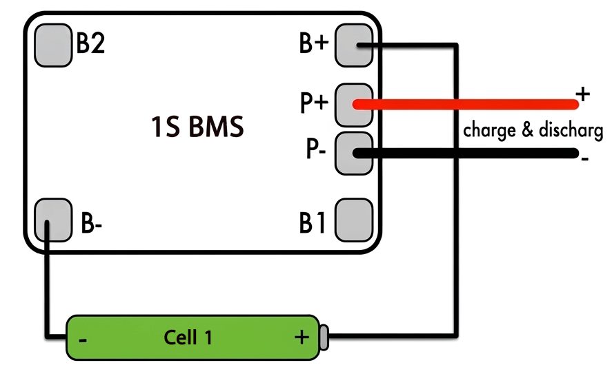
1S BMS
- One lithium cell
- Nominal Voltage: 3.7V
- Full Charge: 4.2V
Applications:
- Flashlights
- Small robots
- Bluetooth speakers
- DIY electronics
2S BMS
- Two lithium cells in series
- Nominal Voltage: 7.4V
- Full Charge: 8.4V

Applications:
- Portable electronics
- RC projects
- Small power tools
3S BMS
- Three lithium cells in series
- Nominal Voltage: 11.1V
- Full Charge: 12.6V

Applications:
- Drones
- Power tools
- UPS systems
4S BMS
- Four lithium cells in series
- Nominal Voltage: 14.8V
- Full Charge: 16.8V
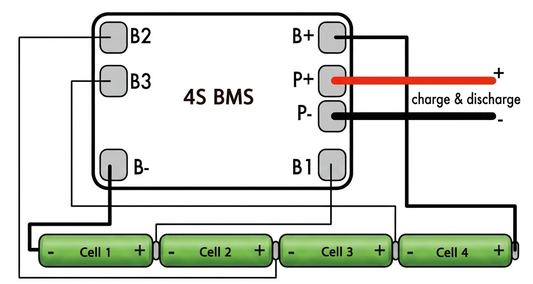
Applications:
- Electric scooters
- Solar batteries
- Industrial devices
Higher-cell BMS boards (6S, 8S, 10S, 13S, etc.) are commonly used in e-bikes, energy storage systems, and electric vehicles.
Construction of a Lithium-Ion Battery Charger BMS Protection Board Module
A Lithium-Ion Charger BMS (Battery Management System) Protection Board Module is an electronic circuit board designed to monitor, protect, and manage rechargeable lithium-ion battery packs. Its construction consists of several key electronic components that work together to ensure safe charging and discharging.
1. Printed Circuit Board (PCB)
The PCB is the foundation of the module. It mechanically supports and electrically connects all components through copper traces. High-quality PCBs are designed to handle the required current while minimizing heat generation and electrical resistance.
2. Battery Management IC (Protection IC)
The Protection Integrated Circuit (IC) is the brain of the BMS. It continuously monitors the battery’s operating conditions and controls the protection functions. It is responsible for:
- Monitoring cell voltage
- Detecting overcharge and over-discharge
- Measuring charging and discharging current
- Detecting short circuits
- Controlling MOSFET switches
- Managing battery safety logic
3. MOSFET Switches
The module typically includes one or more N-channel MOSFETs that act as high-speed electronic switches. They connect or disconnect the battery from the load or charger when unsafe conditions are detected.
Functions include:
- Charging control
- Discharging control
- Overcurrent protection
- Short-circuit isolation
4. Current Sensing Resistor (Shunt Resistor)
A low-resistance shunt resistor measures the current flowing into and out of the battery. The protection IC uses this information to:
- Detect overcurrent
- Limit excessive current
- Monitor battery performance
5. Cell Voltage Monitoring Circuit
Each battery cell is connected to the BMS through voltage-sensing lines. These allow the module to:
- Monitor individual cell voltages
- Detect overcharge
- Detect deep discharge
- Support cell balancing in multi-cell battery packs
6. Cell Balancing Circuit
Many multi-cell BMS boards include a cell balancing circuit that equalizes the voltage across all cells during charging.
Balancing can be:
- Passive balancing: Excess energy from higher-voltage cells is dissipated as heat through resistors.
- Active balancing: Energy is transferred from higher-voltage cells to lower-voltage cells, improving efficiency.
7. Temperature Sensor
Advanced BMS modules use an NTC thermistor to monitor battery temperature. If the temperature exceeds safe limits, the BMS can stop charging or discharging to prevent overheating and potential thermal runaway.
8. Capacitors
Capacitors are used to:
- Filter electrical noise
- Stabilize voltage
- Improve signal quality
- Protect sensitive electronic components
9. Resistors
Various resistors are included for:
- Voltage division
- Current limiting
- Biasing electronic circuits
- Supporting the balancing network
10. Connectors and Terminals
The board includes connection points for the battery pack, charger, and load. Common terminals include:
- B+ – Positive battery terminal
- B− – Negative battery terminal
- P+ – Positive output/charger terminal
- P− – Negative output/charger terminal
- B1, B2, B3, … – Intermediate cell connections for multi-cell battery packs
11. Copper Traces
Thick copper traces carry charging and discharging current across the PCB. Wider traces reduce electrical resistance, improve current-carrying capacity, and help dissipate heat.
12. Optional Communication Interface
Advanced BMS boards may include communication interfaces such as:
- CAN Bus
- UART
- I²C
- SMBus
- Bluetooth
Theory of operation For Battery Charger BMS Protection Board Module
Constant Current (CC)
During the initial charging stage, the battery receives a fixed charging current.
Benefits include:
- Faster charging.
- Controlled temperature rise.
- Stable charging conditions.
Constant Voltage (CV)
After the battery reaches approximately 4.2V, the charger maintains a constant voltage while the charging current gradually decreases.
This stage:
- Prevents overcharging.
- Extends battery life.
- Maximizes charging efficiency.
Overcharge Protection
- If the battery voltage exceeds the safe limit, the protection IC disconnects the charging circuit.
Over-Discharge Protection
- If battery voltage falls below the safe limit (commonly around 2.4–2.9 V depending on the design), the protection circuit disconnects the load to prevent deep discharge.
Overcurrent Protection
- If the load draws excessive current, the MOSFETs disconnect the battery.
Short-Circuit Protection
- In the event of a short circuit, the protection board immediately disconnects the battery to minimize damage and safety risks.
How to Choose the Right (BMS) System
Consider:
- Number of battery cells (1S, 2S, 3S, etc.)
- Maximum charge voltage
- Continuous discharge current
- Peak current rating
- Balance charging support
- Temperature protection
- Board dimensions
- Connector compatibility
- Communication interfaces (if required)
Selecting a BMS that matches your battery chemistry, cell count, and current requirements is essential for safe operation.
Common Problems
Typical issues include:
- Battery not charging
- Battery disconnecting unexpectedly
- Overheating
- Voltage imbalance
- Damaged MOSFETs
- Blown protection IC
- Incorrect wiring
- Poor solder joints
Many problems can be diagnosed by checking cell voltages, wiring, and the condition of the protection board.
Safety Tips
- Use only compatible lithium chargers.
- Never bypass the BMS.
- Avoid mixing old and new cells.
- Match cells by capacity and chemistry.
- Prevent short circuits.
- Keep batteries within recommended temperature ranges.
- Inspect battery packs regularly for swelling or damage.
Applications
Lithium-Ion Battery Charger BMS Protection Board Modules are used in:
- Consumer Electronics
- Bluetooth speakers.
- Wireless headphones.
- Digital cameras.
- Portable gaming devices.
- Power Banks
Protect rechargeable battery packs while safely charging connected devices.
- IoT Devices
- Smart sensors.
- Remote monitoring systems.
- Wireless communication nodes.
- Robotics
- Mobile robots.
- Robotic arms.
- Educational robots.
- Autonomous vehicles.
- Portable Medical Devices
- Portable monitors.
- Medical sensors.
- Battery-powered instruments.
- Solar Energy Systems
Safely charge lithium batteries connected to solar charging circuits.
- DIY Electronics Projects
- Arduino.
- ESP32.
- Raspberry Pi Pico.
- STM32 development boards.
Frequently Asked Questions (FAQs)
Can I use a charger protection board without a protection circuit in the battery?
Yes, provided the board includes its own battery protection circuitry. Verify the module’s specifications before use.
Can I charge a lithium-polymer battery?
Many single-cell charger modules support both lithium-ion and lithium-polymer batteries with a full-charge voltage of 4.2 V. Always confirm compatibility in the datasheet.
Is a TP4056 module suitable for multi-cell battery packs?
No. A standard TP4056 module is intended for a single 3.7 V cell. Multi-cell battery packs require a dedicated Battery Management System (BMS).
Does every charger protection module balance cells?
No. Cell balancing is generally a feature of multi-cell BMS boards, not single-cell charger modules.
Helpful Resources
For readers who want to learn more, these references provide detailed explanations:
- Protection Circuit Module (PCM) Guide
- Battery Management System Design Guide
- Lithium Battery Protection Boards Explained (PCM, PCB & BMS)
- Lithium Battery Protection Board Guide
- TP4056 Lithium Battery Charger Module Guide
Conclusion
Lithium-Ion Battery Charger BMS Protection Board Modules are essential for the safe, efficient, and reliable operation of rechargeable lithium battery systems. Whether used in a simple single-cell device or a large multi-cell battery pack, these modules guard against overcharging, deep discharge, excessive current, short circuits, and, in advanced designs, temperature extremes and cell imbalance. Choosing a protection board with the correct voltage, current rating, and feature set helps maximize battery performance, extend service life, and reduce safety risks, making the BMS a foundational component in modern battery-powered electronics.
شاحن بطاريات (الليثيوم-أيون) و وحدات لوحات الحماية BMS
- مقدمة
- ما هو نظام إدارة البطارية BMS؟
- لماذا نحتاج إلى نظام إدارة البطارية BMS؟
- كيف يعمل نظام إدارة البطارية BMS؟
- وظائف الحماية الأساسية
- الأنواع الأساسية لوحدات لوحات الحماية
- الفرق بين PCM وBMS
- أيهما تختار: PCM أم BMS؟
- الوظائف الرئيسية لوحدة BMS لحماية بطارية الليثيوم
- الأنواع الشائعة من لوحات حماية BMS
- تركيب لوحة BMS لشحن وحماية بطارية الليثيوم-أيون
- آلية عمل لوحة BMS لشحن وحماية البطارية
- كيف تختار نظام BMS المناسب؟
- المشكلات الشائعة
- نصائح السلامة
- التطبيقات
- الأسئلة الشائعة (FAQ)
- المصادر
- الخلاصة
مدة القراءة: 15 دقيقة
مقدمة
تُعد لوحات حماية بطاريات الليثيوم من المكونات الأساسية لضمان التشغيل الآمن للبطاريات القابلة لإعادة الشحن. فهي تعمل كطبقة حماية إلكترونية تراقب البطارية باستمرار وتمنع حالات الشحن الزائد، والتفريغ المفرط، والتيار الزائد، وقصر الدائرة، وارتفاع درجة الحرارة أو انخفاضها إلى مستويات غير آمنة، مما يقلل من احتمالات تلف الخلايا أو حدوث الانفلات الحراري ومخاطر الحريق.
- تعتمد لوحات الحماية على مكونات أساسية مثل دوائر الحماية المتكاملة، وترانزستورات MOSFET، والمقاومات، وحساسات درجة الحرارة لمراقبة الجهد والتيار ودرجة الحرارة باستمرار.
- عند اكتشاف حالة غير آمنة، يمكن لدائرة الحماية فصل البطارية عن الشاحن أو الحمل خلال فترة زمنية قصيرة جدًا لحماية الخلايا.
- توجد حلول مختلفة لحماية البطاريات، بدءًا من لوحات الحماية البسيطة لخلايا الليثيوم المفردة، مرورًا بوحدات PCM، ووصولًا إلى أنظمة BMS المتقدمة المستخدمة في حزم البطاريات متعددة الخلايا.
- تشغيل خلايا الليثيوم دون دائرة حماية مناسبة قد يؤدي إلى تلف دائم في الخلايا، وانخفاض العمر التشغيلي، وزيادة مخاطر ارتفاع الحرارة أو الحريق، خصوصًا في التطبيقات ذات الطاقة العالية مثل الدراجات الكهربائية والطائرات المسيّرة ومحطات الطاقة المحمولة.
- تتطور أنظمة إدارة البطاريات الحديثة لتشمل وظائف أكثر تقدمًا مثل التشخيص الذكي، والتنبؤ بالأعطال، والاتصال اللاسلكي، ومراقبة حالة البطارية عن بُعد.
- يجب دائمًا اختيار لوحة حماية متوافقة مع كيمياء البطارية، وعدد الخلايا، وجهد التشغيل، وتيار الشحن والتفريغ، ومتطلبات السلامة والمعايير المعتمدة.
ما هو نظام إدارة البطارية BMS؟
نظام إدارة البطارية، أو BMS، هو نظام إلكتروني مصمم لمراقبة البطارية القابلة لإعادة الشحن والتحكم في طريقة تشغيلها وحمايتها. ويمكن استخدامه مع خلية واحدة في بعض التطبيقات، إلا أنه يُستخدم بصورة أكثر شيوعًا مع حزم البطاريات التي تتكون من عدة خلايا.
يقوم نظام BMS بمراقبة مجموعة من المتغيرات المهمة مثل جهد الخلايا، والتيار، ودرجة الحرارة، وحالة الشحن، وحالة البطارية، ثم يستخدم هذه المعلومات لمنع تشغيل البطارية خارج الحدود الآمنة.
- حماية البطارية من الشحن الزائد والتفريغ المفرط.
- حماية الخلايا من التيار الزائد وقصر الدائرة.
- مراقبة درجات الحرارة.
- موازنة جهد الخلايا في الحزم متعددة الخلايا.
- تقدير حالة الشحن SOC وحالة صحة البطارية SOH في الأنظمة المتقدمة.
- تسجيل بيانات التشغيل والأعطال في بعض الأنظمة الذكية.
- التواصل مع الشاحن أو وحدة التحكم أو الجهاز المضيف من خلال واجهات مثل CAN وUART وI²C وSMBus.
لماذا نحتاج إلى نظام إدارة البطارية BMS؟
تظهر أهمية نظام BMS بشكل واضح في التطبيقات التي تعتمد على حزم بطاريات الليثيوم عالية الطاقة، مثل السيارات والدراجات الكهربائية وأنظمة تخزين الطاقة. فخلايا الليثيوم تحتاج إلى العمل ضمن نطاقات محددة من الجهد والتيار ودرجة الحرارة، وأي خروج كبير عن هذه الحدود قد يؤدي إلى تدهور أداء الخلية أو تلفها أو، في الحالات الشديدة، إلى مخاطر حرارية خطيرة.
في السيارات الكهربائية مثلًا، يعمل نظام إدارة البطارية كحلقة وصل بين حزمة البطارية وبقية النظام الكهربائي للسيارة. ويمكن أن يتعامل مع بيانات وإشارات متعددة تشمل جهد الخلايا، ودرجة الحرارة، وحالة الشحن، والتيار، ونظام الشحن، واتصالات CAN، وحالات الأعطال وغيرها.
- منع الشحن الزائد الذي قد يؤدي إلى تلف الخلايا وارتفاع درجة حرارتها.
- منع التفريغ العميق الذي يقلل عمر الخلية وسعتها.
- اكتشاف التيار غير الطبيعي وقصر الدائرة.
- مراقبة درجات حرارة الخلايا واتخاذ الإجراءات المناسبة عند تجاوز الحدود المسموح بها.
- موازنة الخلايا للحفاظ على تقارب مستويات الجهد بينها.
- تحسين استخدام الطاقة وإطالة العمر التشغيلي لحزمة البطارية.
كيف يعمل نظام إدارة البطارية BMS؟
يتكون نظام BMS من دائرة إلكترونية تضم دوائر قياس وحماية وتحكم، وقد تحتوي الأنظمة المتقدمة على متحكم دقيق وبرمجيات مخصصة. تقوم هذه الدوائر بجمع البيانات من الخلايا والحساسات، ثم تحليلها ومقارنتها بالحدود المسموح بها.
- يتم قياس جهد كل خلية أو مجموعة من الخلايا المتصلة على التوالي.
- يتم قياس تيار الشحن والتفريغ باستخدام دائرة قياس مناسبة، مثل مقاومة الشنت.
- تتم مراقبة درجة الحرارة باستخدام حساسات مثل NTC.
- إذا ارتفع جهد إحدى الخلايا فوق الحد المسموح، يتم إيقاف الشحن أو فصل البطارية وفق تصميم النظام.
- إذا انخفض الجهد إلى مستوى غير آمن، يقوم النظام بفصل الحمل لمنع التفريغ العميق.
- عند اكتشاف تيار زائد أو قصر في الدائرة، يتم التحكم في MOSFETs لفصل المسار الكهربائي.
- في حزم البطاريات متعددة الخلايا، يمكن لنظام BMS تنفيذ موازنة للخلايا للمساعدة في الحفاظ على تقارب جهودها.

وظائف الحماية الأساسية
1. الحماية من الشحن الزائد
يُعد الشحن الزائد من أخطر الحالات التي يمكن أن تتعرض لها خلايا الليثيوم. فعندما يرتفع جهد الخلية عن الحد المسموح به، قد تحدث تفاعلات كيميائية غير مرغوبة داخلها، مما يؤدي إلى زيادة الحرارة وتدهور المكونات الداخلية للخلية، وقد تتطور الحالة في الظروف الشديدة إلى انفلات حراري.
تراقب دائرة الحماية جهد الخلية أثناء عملية الشحن. وعندما يصل الجهد إلى حد الحماية المحدد، يتم إيقاف مسار الشحن لمنع استمرار زيادة الجهد.
2. الحماية من التفريغ المفرط
يؤدي تفريغ خلية الليثيوم إلى مستوى منخفض جدًا إلى تدهور كيميائي وكهربائي قد يكون دائمًا. لذلك تراقب لوحة الحماية جهد الخلية أثناء التفريغ وتفصل الحمل عندما يصل الجهد إلى الحد الأدنى المسموح به وفق تصميم الخلية.
3. الحماية من التيار الزائد وقصر الدائرة
قد يؤدي حدوث تماس مباشر بين القطبين الموجب والسالب إلى مرور تيار مرتفع جدًا خلال فترة قصيرة. لذلك تستخدم لوحات الحماية MOSFETs ودائرة قياس للتيار لاكتشاف التيار غير الطبيعي وفصل البطارية عن الحمل بسرعة.
4. الحماية من درجات الحرارة غير الآمنة
تعمل خلايا الليثيوم بكفاءة أفضل ضمن نطاق حراري محدد. ارتفاع درجة الحرارة بشكل كبير قد يسرّع تدهور الخلية ويزيد المخاطر، بينما قد يؤدي الشحن في درجات حرارة منخفضة جدًا إلى ظروف تشغيل غير مناسبة.
| حالة التشغيل | النطاق التقريبي | المخاطر عند تجاوز الحدود |
|---|---|---|
| الأداء طويل الأمد | نحو 15 إلى 35 درجة مئوية | تغير سرعة التدهور واختلاف الأداء حسب الخلية |
| درجات الحرارة المرتفعة أثناء التفريغ | تختلف حسب مواصفات الخلية | زيادة التدهور وارتفاع المخاطر الحرارية |
| درجات الحرارة المنخفضة | يجب الالتزام بحدود الشركة المصنعة | زيادة المقاومة الداخلية واحتمال حدوث أضرار عند الشحن في ظروف غير مناسبة |
| الحرارة الشديدة | تتطلب الإيقاف وفق مواصفات الخلية | ارتفاع خطر التلف الحراري والانفلات الحراري |
الأنواع الأساسية لوحدات لوحات الحماية
لوحة PCB للحماية
هي لوحة إلكترونية تركز بصورة أساسية على وظائف الحماية الكهربائية، مثل حماية الشحن الزائد والتفريغ المفرط والتيار الزائد وقصر الدائرة. وغالبًا ما تستخدم MOSFETs لفصل البطارية عند اكتشاف حالة غير آمنة.
وحدة PCM للحماية
وحدة PCM هي دائرة حماية مخصصة للبطارية، وغالبًا ما تكون بسيطة ومنخفضة التكلفة. وقد تتضمن بعض وحدات PCM وظائف موازنة أساسية للخلايا في الحزم متعددة الخلايا، إلا أن قدراتها في المراقبة والتحليل عادةً أقل من أنظمة BMS المتقدمة.
نظام BMS لإدارة البطارية
نظام BMS هو الحل الأكثر تطورًا، ويمكن أن يجمع بين الحماية والمراقبة والموازنة والتشخيص وحساب حالة الشحن وحالة صحة البطارية والاتصال مع الأنظمة الخارجية. ويكون مناسبًا بصورة خاصة لحزم البطاريات الكبيرة أو التطبيقات التي تتطلب مستوى أعلى من التحكم والمراقبة.
تصنيف وحدات الحماية حسب مستوى الوظائف
الحماية الأساسية
- الحماية من الشحن الزائد.
- الحماية من التفريغ المفرط.
- الحماية من التيار الزائد.
- الحماية من قصر الدائرة.
الحماية المتوسطة
- الحماية من عكس القطبية.
- الحماية من زيادة الجهد.
- الحماية من انخفاض الجهد.
- مراقبة درجة الحرارة.
الحماية المتقدمة
- موازنة الخلايا.
- المراقبة الفردية لكل خلية.
- حساب حالة الشحن SOC.
- تقدير حالة صحة البطارية SOH.
- تشخيص الأعطال.
- تسجيل البيانات.
- الاتصال عبر CAN أو UART أو I²C أو SMBus أو تقنيات الاتصال الأخرى.
الفرق بين PCM وBMS
يشترك كل من PCM وBMS في هدف أساسي هو حماية البطارية، لكن الفرق الرئيسي يكمن في مستوى المراقبة والتحكم والذكاء والاتصال. وتكون وحدة PCM عادةً أبسط وأقل تكلفة، بينما يوفر نظام BMS وظائف أكثر تقدمًا لإدارة حزمة البطارية.
وحدة حماية البطارية PCM
- دائرة حماية مستقلة تركز على وظائف الحماية الأساسية.
- تعتمد غالبًا على دوائر إلكترونية ثابتة دون نظام برمجي متقدم.
- توفر حماية من الشحن الزائد والتفريغ المفرط والتيار الزائد وقصر الدائرة، حسب التصميم.
- قدراتها في معرفة الحالة الدقيقة للبطارية محدودة.
- لا توفر عادةً إمكانات متقدمة للتحكم في الشاحن أو الحمل.
- قد تكون مراقبة درجة الحرارة محدودة أو غير متوفرة، حسب نوع الوحدة.
- الموازنة، إن وجدت، تكون عادةً بسيطة.
- تتميز بانخفاض التكلفة وسهولة الاستخدام.
نظام إدارة البطارية BMS
- يحتوي في الأنظمة المتقدمة على متحكم دقيق وبرمجيات مخصصة.
- يستطيع تحليل عدة قياسات في الوقت نفسه.
- يمكنه تقدير حالة الشحن SOC وحالة صحة البطارية SOH.
- يوفر مراقبة أكثر تفصيلًا للخلايا ودرجات الحرارة والتيار.
- يدعم موازنة الخلايا وفق تصميم النظام.
- يمكن أن يحتوي على واجهات اتصال مثل CAN وI²C وUART وSMBus.
- يمكنه تبادل البيانات مع الشاحن أو وحدة التحكم أو النظام المضيف.
- قد يوفر تشخيصًا للأعطال وتسجيلًا لأحداث التشغيل.
- يمكن استخدامه في الأنظمة التي تحتاج إلى مراقبة وإدارة متقدمة للطاقة.
مقارنة تقنية بين PCM وBMS
| الخاصية | PCM | BMS |
|---|---|---|
| وظائف الحماية | حماية أساسية من الشحن الزائد والتفريغ والتيار الزائد وقصر الدائرة، حسب التصميم. | حماية ومراقبة أكثر شمولًا، وقد تشمل الحرارة والموازنة والتشخيص. |
| مراقبة الحرارة | محدودة أو غير متوفرة في بعض الأنواع. | يمكن أن تتضمن عدة حساسات وقرارات حماية مرتبطة بالحرارة. |
| الاتصال | عادةً لا توجد واجهة اتصال متقدمة. | قد يدعم CAN وSMBus وI²C وUART وغيرها. |
| موازنة الخلايا | محدودة أو غير متوفرة، حسب الوحدة. | يمكن أن يدعم موازنة سلبية أو نشطة وفق التصميم. |
| المراقبة | مراقبة أساسية لحدود الجهد والتيار. | مراقبة متقدمة للجهد والتيار والحرارة وحالة البطارية والأعطال. |
| التطبيقات | الأجهزة البسيطة وحزم البطاريات الصغيرة والحساسة للتكلفة. | الدراجات والمركبات الكهربائية والروبوتات والطائرات المسيّرة وأنظمة تخزين الطاقة وغيرها. |
| التكلفة والتعقيد | أقل تكلفة وأبسط في الدمج. | أعلى تكلفة وأكثر تعقيدًا في التصميم والتهيئة. |
باختصار، يمكن اعتبار PCM حلًا مناسبًا للحماية الأساسية في التطبيقات البسيطة، بينما يكون BMS أكثر ملاءمة عندما تكون هناك حاجة إلى المراقبة والموازنة وإدارة الطاقة والتشخيص والاتصال مع الأنظمة الأخرى.

محدودية استخدام PCM في بعض التطبيقات
- قد لا توفر بعض وحدات PCM مراقبة حرارية كافية، مما يجعل اختيارها غير مناسب للتطبيقات التي تتطلب مراقبة دقيقة لدرجة الحرارة.
- قدرات الاتصال والمراقبة عن بُعد تكون محدودة جدًا.
- لا يمكن عادةً الحصول على معلومات تفصيلية عن حالة الشحن أو صحة البطارية.
- لا توفر غالبًا خوارزميات متقدمة لتحسين استهلاك الطاقة وعمر البطارية.
- تظل مناسبة في العديد من التطبيقات البسيطة عندما تكون الحماية الأساسية هي الحاجة الرئيسية.
أيهما تختار: PCM أم BMS؟
يعتمد الاختيار على طبيعة التطبيق ومستوى الحماية والمراقبة المطلوب. فإذا كان الجهاز بسيطًا ويستخدم خلية واحدة أو حزمة صغيرة، وكانت الحاجة تقتصر على الحماية الأساسية، فقد تكون وحدة PCM مناسبة.
أما إذا كان النظام يعتمد على عدة خلايا متصلة على التوالي، أو يحتاج إلى موازنة الخلايا ومراقبة الحرارة وحساب حالة الشحن والتشخيص والاتصال مع وحدات أخرى، فإن BMS يكون الخيار الأكثر ملاءمة.
الوظائف الرئيسية لوحدة BMS لحماية بطارية الليثيوم
1. الحماية من الشحن الزائد
تحتاج خلايا الليثيوم إلى الالتزام بجهد الشحن الأقصى المحدد من الشركة المصنعة. بالنسبة للعديد من خلايا الليثيوم-أيون التقليدية، يكون جهد الشحن الكامل الشائع نحو 4.2 فولت لكل خلية، لكن القيمة الفعلية تعتمد على كيمياء الخلية وتصميمها.
- يمنع ارتفاع جهد الخلية فوق الحد المسموح.
- يساعد على تقليل تدهور الخلية.
- يحد من ارتفاع الحرارة والمخاطر المرتبطة بالشحن غير الصحيح.
2. الحماية من التفريغ المفرط
يؤدي التفريغ العميق إلى الإضرار بالخلية وتقليل سعتها وعمرها. لذلك يفصل BMS الحمل عندما يصل جهد الخلية إلى الحد الأدنى المحدد في تصميم الحماية.
3. الحماية من التيار الزائد
عندما يسحب الحمل تيارًا يتجاوز الحد المسموح، تقوم دائرة الحماية بفصل البطارية لتقليل خطر ارتفاع الحرارة أو تلف الخلايا أو الأسلاك أو المكونات الإلكترونية.
4. الحماية من قصر الدائرة
في حالة حدوث تماس مباشر بين أطراف البطارية، قد يرتفع التيار بصورة كبيرة جدًا. ولذلك تعمل دائرة الحماية على فصل البطارية بسرعة لتقليل مخاطر التلف والحرارة والحريق.
5. الحماية الحرارية
تستخدم أنظمة BMS المتقدمة حساسات حرارية مثل NTC لمراقبة درجة حرارة الخلايا. وعند الوصول إلى درجة حرارة غير آمنة، يمكن للنظام إيقاف الشحن أو التفريغ وفقًا للحدود المحددة.
6. موازنة الخلايا
لا تتدهور جميع خلايا الحزمة بنفس المعدل. لذلك تساعد موازنة الخلايا على إبقاء جهود الخلايا المتصلة على التوالي ضمن مستويات متقاربة، وهو أمر مهم لتحسين الاستفادة من سعة الحزمة وتقليل الاختلال بين الخلايا.
- الموازنة السلبية: يتم التخلص من جزء من الطاقة الزائدة في الخلايا ذات الجهد الأعلى على شكل حرارة عبر مقاومات.
- الموازنة النشطة: يتم نقل الطاقة من الخلايا ذات الجهد الأعلى إلى الخلايا ذات الجهد الأقل، وهي أكثر كفاءة ولكنها أكثر تعقيدًا.
الأنواع الشائعة من لوحات BMS لبطاريات الليثيوم-أيون
نظام 1S
- خلية ليثيوم واحدة.
- الجهد الاسمي الشائع: 3.7 فولت.
- جهد الشحن الكامل الشائع للخلايا التقليدية: 4.2 فولت.
- الاستخدامات: المصابيح، السماعات المحمولة، المشاريع الإلكترونية والأجهزة الصغيرة.
نظام 2S
- خليتان متصلتان على التوالي.
- الجهد الاسمي الشائع: 7.4 فولت.
- جهد الشحن الكامل الشائع: 8.4 فولت.
- الاستخدامات: الأجهزة المحمولة والمشاريع الإلكترونية وبعض الأدوات الصغيرة.
نظام 3S
- ثلاث خلايا متصلة على التوالي.
- الجهد الاسمي الشائع: 11.1 فولت.
- جهد الشحن الكامل الشائع: 12.6 فولت.
- الاستخدامات: بعض الطائرات المسيّرة والأدوات الكهربائية وأنظمة UPS.
نظام 4S
- أربع خلايا متصلة على التوالي.
- الجهد الاسمي الشائع: 14.8 فولت.
- جهد الشحن الكامل الشائع: 16.8 فولت.
- الاستخدامات: بعض الدراجات الكهربائية وأنظمة الطاقة الشمسية والأجهزة الصناعية.
توجد أيضًا لوحات لحزم أكبر مثل 6S و8S و10S و13S وغيرها، وتستخدم في تطبيقات تشمل الدراجات الكهربائية وأنظمة تخزين الطاقة والمركبات الكهربائية، مع ضرورة اختيار اللوحة وفق عدد الخلايا والكيمياء والتيار المطلوب.
تركيب لوحة BMS لحماية وشحن بطارية الليثيوم-أيون
لوحة BMS هي دائرة إلكترونية مصممة لمراقبة البطارية وحمايتها وإدارة تشغيلها. وتتكون من مجموعة من المكونات الإلكترونية التي تعمل معًا لتحقيق وظائف القياس والحماية والتحكم.
1. لوحة الدائرة المطبوعة PCB
تمثل PCB الأساس الميكانيكي والكهربائي للوحدة، حيث تحمل المكونات الإلكترونية وتربط بينها بواسطة مسارات نحاسية. ويجب تصميمها بحيث تتحمل تيار التشغيل المطلوب وتقلل الفقد والحرارة.
2. دائرة إدارة أو حماية البطارية IC
تعمل دائرة الحماية المتكاملة على مراقبة ظروف تشغيل البطارية وتنفيذ منطق الحماية. ومن وظائفها:
- مراقبة جهد الخلايا.
- اكتشاف الشحن الزائد والتفريغ المفرط.
- مراقبة التيار.
- اكتشاف حالات قصر الدائرة.
- التحكم في MOSFETs.
- تنفيذ منطق الحماية وفق حدود التصميم.
3. ترانزستورات MOSFET
تعمل MOSFETs كمفاتيح إلكترونية سريعة تسمح بتوصيل البطارية أو فصلها عن الشاحن والحمل عند اكتشاف حالة غير آمنة.
- التحكم في مسار الشحن.
- التحكم في مسار التفريغ.
- المساعدة في الحماية من التيار الزائد.
- فصل البطارية عند حدوث قصر أو حالة خطرة.
4. مقاومة قياس التيار Shunt Resistor
هي مقاومة منخفضة القيمة تستخدم لقياس التيار المار في الدائرة. وتستخدم دائرة الحماية فرق الجهد الناتج عنها لتحديد مقدار التيار واكتشاف حالات التيار الزائد.
5. دائرة مراقبة جهد الخلايا
تسمح خطوط قياس الجهد بمراقبة الخلايا بشكل فردي في الحزم متعددة الخلايا، مما يساعد على اكتشاف الخلايا ذات الجهد المرتفع أو المنخفض، وتنفيذ الموازنة في الأنظمة التي تدعمها.
6. دائرة موازنة الخلايا
تستخدم دائرة الموازنة في الحزم متعددة الخلايا للمساعدة على تقليل الفروق في الجهد بين الخلايا أثناء الشحن. ويمكن أن تكون الموازنة سلبية أو نشطة بحسب تصميم BMS.
7. حساس درجة الحرارة
يستخدم BMS المتقدم عادةً حساس NTC لمراقبة درجة حرارة الخلايا. وإذا تجاوزت درجة الحرارة الحدود المحددة، يمكن للنظام إيقاف الشحن أو التفريغ.
8. المكثفات
- تقليل الضوضاء الكهربائية.
- تثبيت الجهود في الدوائر.
- تحسين جودة الإشارات.
- المساعدة في حماية الدوائر الحساسة.
9. المقاومات
- تقسيم الجهد.
- تحديد التيار.
- ضبط نقاط التشغيل في الدوائر.
- دعم دوائر موازنة الخلايا.
10. الموصلات والأطراف
- B+: الطرف الموجب للبطارية.
- B−: الطرف السالب للبطارية.
- P+: الطرف الموجب المشترك للحمل والشحن في بعض التصاميم.
- P−: الطرف السالب المشترك للحمل والشحن في بعض التصاميم.
- B1 وB2 وB3 وغيرها: نقاط توصيل الخلايا الوسيطة في الحزم متعددة الخلايا.
11. المسارات النحاسية
تحمل المسارات النحاسية تيار الشحن والتفريغ بين المكونات والأطراف. ويؤدي استخدام مسارات مناسبة للتيار إلى تقليل المقاومة والفقد الحراري.
12. واجهات الاتصال الاختيارية
- CAN Bus.
- UART.
- I²C.
- SMBus.
- Bluetooth في بعض الأنظمة.
نظرية تشغيل لوحة BMS للشحن والحماية
مرحلة التيار الثابت CC
في بداية عملية الشحن، يعمل الشاحن عادةً في وضع التيار الثابت، حيث يتم تزويد البطارية بتيار شحن مضبوط بينما يرتفع جهد الخلية تدريجيًا.
- يساعد على تسريع عملية الشحن ضمن الحدود المسموح بها.
- يسمح بالتحكم في مقدار التيار.
- يساعد على الحفاظ على ظروف شحن مستقرة.
مرحلة الجهد الثابت CV
عندما يصل جهد الخلية إلى جهد الشحن المحدد، ينتقل الشاحن إلى مرحلة الجهد الثابت. عندها يتم الحفاظ على الجهد عند القيمة المستهدفة بينما ينخفض تيار الشحن تدريجيًا.
- يحد من تجاوز جهد الشحن المطلوب.
- يساعد على إكمال الشحن بصورة صحيحة.
- يساهم في تقليل إجهاد الخلية مقارنةً بالاستمرار في رفع الجهد.
الحماية من الشحن الزائد
إذا تجاوز جهد الخلية حد الحماية المحدد، تقوم دائرة الحماية بفصل مسار الشحن أو اتخاذ الإجراء المحدد في تصميم النظام.
الحماية من التفريغ المفرط
عندما ينخفض جهد الخلية إلى الحد الأدنى المحدد، يفصل BMS الحمل لمنع استمرار التفريغ. وتختلف قيمة الحد الفعلية بحسب كيمياء الخلية وتصميم الحماية.
الحماية من التيار الزائد
إذا تجاوز التيار الحد المسموح، تقوم دائرة الحماية بفصل MOSFETs لحماية البطارية والدائرة الكهربائية من التيار المرتفع والحرارة الزائدة.
الحماية من قصر الدائرة
عند حدوث قصر كهربائي، تعمل دائرة الحماية على فصل البطارية بسرعة لتقليل شدة التيار والحد من الأضرار المحتملة.
كيف تختار نظام BMS المناسب؟
اختيار BMS الصحيح لا يعتمد على عدد الخلايا فقط، بل يجب أن يتوافق النظام بالكامل مع مواصفات البطارية والشاحن والحمل.
- عدد الخلايا المتصلة على التوالي: 1S أو 2S أو 3S أو غيرها.
- كيمياء البطارية ونوع الخلايا المستخدمة.
- جهد الشحن الأقصى.
- تيار الشحن المطلوب.
- تيار التفريغ المستمر.
- تيار التفريغ اللحظي أو تيار الذروة.
- دعم موازنة الخلايا عند الحاجة.
- وجود حماية حرارية مناسبة.
- أبعاد اللوحة وطريقة تركيبها.
- نوع الموصلات وترتيب أطراف التوصيل.
- وجود واجهات اتصال مثل CAN أو UART أو I²C إذا كان التطبيق يحتاج إليها.
- التأكد من توافق BMS مع نوع الخلايا وليس الاعتماد على الجهد فقط.
يجب أن تتطابق مواصفات BMS مع البطارية من حيث عدد الخلايا والكيمياء والجهد والتيار. استخدام لوحة غير مناسبة قد يؤدي إلى ضعف الأداء أو عدم عمل الحماية بالشكل المطلوب.
المشكلات الشائعة
- البطارية لا تشحن.
- البطارية تفصل بشكل مفاجئ أثناء التشغيل.
- ارتفاع درجة حرارة البطارية أو لوحة الحماية.
- وجود اختلاف كبير في جهد الخلايا.
- تلف MOSFETs.
- تلف دائرة الحماية المتكاملة.
- توصيل الأسلاك بطريقة خاطئة.
- ضعف أو تلف نقاط اللحام.
- استخدام شاحن غير متوافق مع البطارية.
- اختيار BMS بتيار أقل من تيار الحمل المطلوب.
يمكن أن تبدأ عملية التشخيص بفحص جهد كل خلية، والتحقق من أسلاك التوصيل، وفحص أطراف BMS، والتأكد من توافق الشاحن والحمل مع مواصفات البطارية. ويجب عدم تجاوز أو تعطيل دائرة الحماية بغرض حل المشكلة.
نصائح السلامة
- استخدم شاحنًا متوافقًا مع كيمياء البطارية وعدد خلاياها.
- لا تقم أبدًا بتجاوز أو إلغاء وظيفة BMS أو دائرة الحماية.
- لا تخلط خلايا قديمة مع خلايا جديدة داخل الحزمة نفسها دون تصميم واختبار مناسب.
- استخدم خلايا متوافقة في السعة والكيمياء والمواصفات الكهربائية.
- احمِ أطراف البطارية من قصر الدائرة.
- لا تستخدم البطارية خارج نطاقات الحرارة المحددة من الشركة المصنعة.
- افحص البطارية دوريًا بحثًا عن الانتفاخ أو التسرب أو التلف أو الروائح غير الطبيعية.
- أوقف استخدام البطارية إذا ظهرت عليها علامات تلف أو سخونة غير طبيعية.
- استخدم مكونات حماية وشحن مناسبة ومطابقة لمواصفات البطارية.
التطبيقات
الأجهزة الإلكترونية
- السماعات المحمولة.
- سماعات الأذن اللاسلكية.
- الكاميرات الرقمية.
- أجهزة الألعاب المحمولة.
بنوك الطاقة Power Banks
تستخدم دوائر الحماية وإدارة البطارية لحماية خلايا بنك الطاقة أثناء الشحن والتفريغ وتزويد الأجهزة بالطاقة.
أجهزة إنترنت الأشياء IoT
- أجهزة الاستشعار الذكية.
- أنظمة المراقبة عن بُعد.
- عقد الاتصال اللاسلكية.
الروبوتات
- الروبوتات المتحركة.
- الأذرع الروبوتية.
- الروبوتات التعليمية.
- المركبات ذاتية التشغيل.
الأجهزة الطبية المحمولة
- أجهزة المراقبة المحمولة.
- أجهزة الاستشعار الطبية.
- الأجهزة الطبية التي تعمل بالبطارية.
أنظمة الطاقة الشمسية
تُستخدم أنظمة إدارة وحماية البطاريات مع أنظمة الطاقة الشمسية لضمان شحن بطاريات الليثيوم وتشغيلها ضمن الحدود المناسبة.
المشاريع الإلكترونية DIY
- Arduino.
- ESP32.
- Raspberry Pi Pico.
- STM32.
- المشاريع التعليمية والتجريبية التي تعمل بالبطاريات.
الأسئلة الشائعة FAQ
هل يمكن استخدام وحدة شحن وحماية للبطارية دون إضافة دائرة حماية أخرى؟
نعم، إذا كانت الوحدة نفسها تحتوي على دائرة حماية مناسبة للبطارية. ولكن يجب قراءة مواصفات الوحدة والتأكد من أنها تدعم نوع البطارية وعدد الخلايا وتيار الشحن والتفريغ المطلوب.
هل يمكنني استخدام لوحة شحن وحماية مع بطارية ليثيوم بوليمر Li-Po؟
يمكن لبعض وحدات الشحن المصممة لخلية ليثيوم واحدة أن تعمل مع خلايا Li-Po ذات جهد الشحن الكامل المناسب، ولكن لا ينبغي افتراض التوافق تلقائيًا. يجب التأكد من مواصفات الوحدة والبطارية قبل استخدامها.
هل وحدة TP4056 مناسبة لحزم البطاريات متعددة الخلايا؟
لا. وحدة TP4056 التقليدية مصممة لشحن خلية ليثيوم واحدة بجهد اسمي يقارب 3.7 فولت وجهد شحن كامل يبلغ 4.2 فولت. أما الحزم متعددة الخلايا فتحتاج إلى دائرة شحن وحماية مصممة خصيصًا لعدد الخلايا المستخدم.
هل تحتوي جميع وحدات الحماية والشحن على وظيفة موازنة الخلايا؟
لا. وظيفة موازنة الخلايا ليست موجودة في جميع وحدات الشحن والحماية، وتكون عادةً مرتبطة بالحزم متعددة الخلايا وبأنظمة BMS المصممة لمراقبة كل خلية بشكل مستقل.
المصادر
للحصول على فهم أعمق لتقنيات حماية وإدارة بطاريات الليثيوم، يمكن دراسة الموضوعات التالية:
- دليل وحدات حماية البطارية (PCM)
- مبادئ تصميم أنظمة إدارة البطارية
- شرح الفروق بين PCB وPCM وBMS
- دليل لوحات حماية بطاريات الليثيوم
- شرح وحدات شحن بطاريات الليثيوم مثل TP4056
الخلاصة
تُعد لوحات حماية وشحن بطاريات الليثيوم-أيون من أهم المكونات المسؤولة عن التشغيل الآمن والموثوق للبطاريات القابلة لإعادة الشحن. سواء كانت البطارية عبارة عن خلية واحدة في جهاز صغير أو حزمة كبيرة تتكون من عدد كبير من الخلايا، فإن دائرة الحماية المناسبة تساعد على منع الشحن الزائد، والتفريغ المفرط، والتيار الزائد، وقصر الدائرة، ودرجات الحرارة غير الآمنة.
في الحزم متعددة الخلايا، تصبح موازنة الخلايا ومراقبة كل خلية على حدة أكثر أهمية، ولذلك يوفر BMS المتقدم مستوى أعلى من الإدارة والمراقبة مقارنةً بدوائر الحماية البسيطة.
اختيار نظام الحماية الصحيح يجب أن يعتمد على كيمياء الخلايا، وعدد الخلايا المتصلة على التوالي، وجهد الشحن، وتيار الشحن والتفريغ، ومتطلبات الحرارة، ووظائف الموازنة والاتصال المطلوبة. ولا يكفي أن تتطابق اللوحة مع الجهد الاسمي فقط.
إن استخدام BMS أو PCM مناسب لا يحسن أداء البطارية فحسب، بل يساعد أيضًا على إطالة عمرها وتقليل مخاطر التشغيل غير الآمن. ولهذا يجب التعامل مع دوائر حماية بطاريات الليثيوم باعتبارها جزءًا أساسيًا من تصميم النظام وليست مكونًا اختياريًا.
الاستخدام الآمن يبدأ باختيار نظام حماية مناسب ومتوافق مع البطارية.
Related Posts

Buck Converter vs LDO Regulator: How to Choose the Right One?
Buck Converter vs LDO Regulator: How to Choose the Right One? Contents List Introduction.

Buck vs Boost Converters: How to Choose the Right DC-DC Converter?
Buck vs Boost Converters: How to Choose the Right DC-DC Converter? Contents List Introduction

The Relays
The Relays Contents List Introduction. What Is a Relay? How Does a Relay Work?

Everything You Need to Know About EEPROM
Contents List Introduction to EEPROM. What Is EEPROM? How Does EEPROM Work? Main Types

TM1990A iButton Access: Smart Reader & Security Key
TM1990A iButton Access: Smart Reader & Security Key Contents List Introduction What Is the
Leave a comment
You must be logged in to post a comment.