


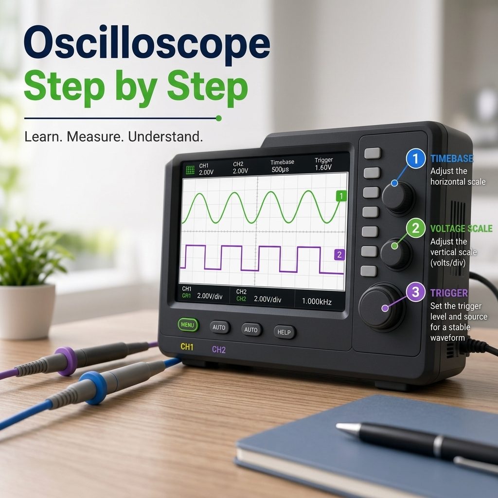
Oscilloscope Step by Step
Contents List
- Introduction.
- What Is an Oscilloscope?
- Understanding the Oscilloscope Display.
- Understanding V/div and Time/div.
- Understanding Triggering.
- Understanding Oscilloscope Probes.
- 1X vs 10X Probes.
- Probe Compensation.
- AC vs DC Coupling.
- How to Connect an Oscilloscope Safely?
- First Oscilloscope Setup — Step by Step.
- Measuring Voltage.
- Measuring Frequency and Period.
- Measuring Pulse Width and Duty Cycle.
- Measuring Rise and Fall Time.
- Using Cursors and Automatic Measurements.
- Acquisition Modes and Single Trigger.
- Bandwidth, Sampling Rate, and Memory Depth.
- Common Beginner Mistakes.
- Practical Oscilloscope Examples.
- Basic Oscilloscope Troubleshooting.
- Frequently Asked Questions.
- Conclusion.
Reading Time Approximately is 20 minute
Introduction

Have you ever found yourself troubleshooting a circuit, needing more information than a simple Multimeter can provide? If you need to uncover information They can be used to observe signals, measure timing, analyze PWM and digital pulses, examine power-supply ripple, and locate circuit faults.
Learning to use an Oscilloscope is a fundamental skill for anyone in electronics, from students and hobbyists to seasoned engineers. They allow you to see electric signals as they vary over time, which can be critical in diagnosing why your 555 timer circuit isn’t blinking correctly, or why your noise maker isn’t reaching maximum annoyance levels.
Many engineers struggle with unstable displays, confusing triggers, or measurements that don’t line up with expectations, and those issues can slow down development or point you in the wrong direction.
When you understand how to use a scope properly, you move through debugging faster, make better design decisions, and avoid chasing problems that aren’t really there. Strong oscilloscope skills help you diagnose noise, timing issues, or distortion with confidence.
Oscilloscopes can be line powered or battery powered; they can be big or small. Battery power and smaller size, for portability, are typically required for field use. Some oscilloscopes have built-in multimeters giving you both numbers and pictures. In many cases, these kinds of oscilloscopes can replace a multimeter
This guide will help you read an oscilloscope with confidence, how to use an oscilloscope step by step, from understanding the display and connecting a probe to making measurements and troubleshooting common problems. so you can interpret signals and troubleshoot circuits effectively.
What Is an Oscilloscope?
An oscilloscope, often called a scope or O-scope, is an electronic test instrument that displays an electrical signal as a waveform.
The basic principle is:
Voltage is displayed vertically, while time is displayed horizontally.

This allows you to see how a signal changes rather than simply knowing its numerical value.
An oscilloscope can display:
- DC and AC voltage signals.
- Sine waves.
- Square waves.
- Pulse and PWM signals.
- Digital signals.
- Audio and sensor signals.
- Power-supply ripple.
- Noise and interference.
- Transient spikes and glitches.
A multimeter might tell you that a circuit has 5 V, while an oscilloscope can show whether that 5 V is stable, noisy, pulsating, or producing unwanted spikes.
Understanding the Oscilloscope Display
The oscilloscope display is based on a grid called the graticule.
Vertical Axis — Voltage
The vertical or Y-axis represents voltage.
The V/div setting determines how much voltage is represented by each vertical division.
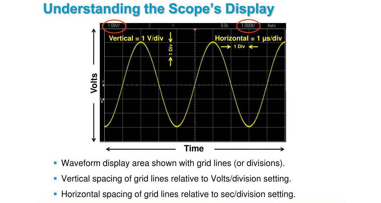
For example, at 2 V/div, a waveform covering 3 vertical divisions has:
Vpp = 3 × 2 V = 6 V
Horizontal Axis — Time
The horizontal or X-axis represents time.
The Time/div setting determines how much time is represented by each horizontal division.
For example, if one complete cycle occupies 4 divisions at 1 ms/div:
T = 4 × 1 ms = 4 ms
Frequency is:
f = 1/T = 1/0.004 = 250 Hz
Channels
Multi-channel oscilloscopes allow you to display multiple signals simultaneously. This is useful for comparing signals and examining their timing relationship.
Understanding V/div and Time/div
V/div and Time/div are two of the most important controls for beginners.
V/div
V/div controls the vertical voltage scale.
- Decrease V/div when the waveform is too small.
- Increase V/div when the waveform is too large or clipped.
The goal is to make the waveform large enough to examine without exceeding the screen.

Time/div
Time/div controls the horizontal time scale.
- Use a smaller value to examine fast signals.
- Use a larger value to observe slow-changing signals.
Together, these controls determine how much of the signal is visible on the screen.
Understanding Triggering
Triggering tells the oscilloscope when to use a particular point in the incoming signal as the timing reference for displaying the waveform.
Without proper triggering, a repeating waveform may appear to move continuously or look unstable.

Trigger Source
Selects the channel used to trigger the waveform, such as CH1.
Trigger Level
Sets the voltage level at which the oscilloscope recognizes the trigger event.
Trigger Edge
The oscilloscope can normally trigger on:
- Rising edge.
- Falling edge.
Trigger Mode
Common modes include:
- Auto.
- Normal.
- Single.
Auto is a convenient starting point for beginners. Normal provides more controlled triggering, while Single is useful for capturing one-time events.
Understanding Oscilloscope Probes
The probe connects the oscilloscope to the circuit under test. Its resistance, capacitance, attenuation, bandwidth, and grounding can affect the measurement.

A typical passive probe has:
- Probe tip → connected to the signal test point.
- Ground clip → connected to the appropriate circuit reference.
For fast signals, use the shortest practical ground connection. A long ground lead can introduce inductance and produce ringing or other measurement artifacts.
1X vs 10X Probes
Many passive probes provide 1X and 10X settings.
1X probe:
- Provides approximately no attenuation.
- Offers higher sensitivity for small signals.
- Generally presents greater capacitance to the circuit.
10X probe:
- Attenuates the signal approximately 10:1.
- Reduces circuit loading.
- Is commonly used for general-purpose measurements.

- For general measurements, 10X is usually a good starting point, provided the signal and probe ratings are appropriate.
- Always make sure the oscilloscope’s probe setting matches the physical probe setting.
Probe Compensation
Passive probes should normally be compensated to match the oscilloscope input.
Most oscilloscopes provide a built-in square-wave calibration signal.
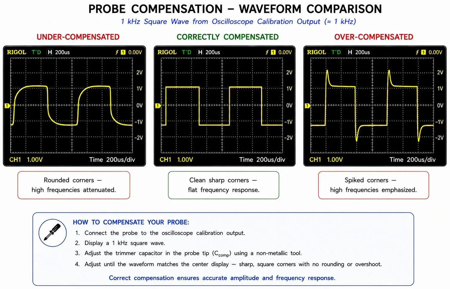
Basic Procedure
- Connect the probe to CH1.
- Connect the probe tip to the calibration output.
- Connect the ground clip to the corresponding ground terminal.
- Display the square wave.
- Adjust the probe compensation screw.
- Stop when the waveform corners appear correctly shaped.
Poor compensation can cause rounded corners, overshoot, or undershoot.
AC vs DC Coupling
Input coupling determines whether the DC component of the signal is displayed.

DC Coupling
- DC coupling displays both the DC level and AC variations.
- For example, a 12 V DC supply with ripple can be viewed around its actual 12 V level.
AC Coupling
- AC coupling blocks the DC component and allows the AC variation to be examined more easily.
- For example, AC coupling can make small ripple on a 12 V supply easier to observe.
- For general measurements, DC coupling is normally the best starting point.
How to Connect an Oscilloscope Safely?
Safety is essential before making any measurement.
Always:
- Estimate the voltage being measured.
- Check the oscilloscope input rating.
- Check the probe voltage rating.
- Check the applicable measurement category rating.
- Use the correct probe attenuation.
- Understand where the oscilloscope ground is connected.
- Never assume the probe ground clip is electrically isolated.
Important Grounding Warning
On many bench oscilloscopes, the standard probe ground is connected to protective earth. Connecting it to an inappropriate point can create a short circuit, damage equipment, or create a serious electrical hazard.
Never connect a standard grounded oscilloscope probe directly across mains or another floating/high-energy circuit unless you have the appropriate measurement equipment, method, and training.
For hazardous measurements, use properly rated differential or isolated measurement equipment where appropriate.
First Oscilloscope Setup — Step by Step
For a first measurement, use this basic sequence:
- Turn on the oscilloscope.
- Select Default Setup or use AUTOSET to obtain an initial waveform.
- Enable CH1.
- Connect the probe tip to the signal.
- Connect the probe ground to the appropriate circuit reference.
- Verify the probe attenuation setting.
- Adjust V/div.
- Adjust Time/div.
- Set the trigger source, edge, level, and mode.
- Use cursors or automatic measurements to examine the signal.
AUTOSET is useful for getting started, but learning the controls manually is important for troubleshooting.
Measuring Voltage
Common oscilloscope voltage measurements include:
- Vmax.
- Vmin.
- Vpp.
- Vp.
- Vrms.

The basic manual relationship is:
Voltage = Number of vertical divisions × V/div
For example, if a waveform covers 4 divisions at 1 V/div:
Vpp = 4 × 1 V = 4 V
If it is centered around 0 V:
Vp ≈ 2 V
Measuring Period and Frequency
- Period (T) is the time required for one complete cycle.
- Frequency (f) is the number of cycles per second.
The relationship is:
f = 1/T

To measure period manually:
- Display a stable repeating waveform.
- Select a suitable Time/div setting.
- Measure one complete cycle.
- Count the horizontal divisions.
- Multiply by Time/div.
For example:
4 divisions × 1 ms/div = 4 ms
Therefore:
f = 1/4 ms = 250 Hz
Measuring Pulse Width and Duty Cycle
These measurements are especially useful for digital signals and PWM.
Pulse Width
Pulse width is the amount of time a pulse remains at a specified level, commonly the high level.
Duty Cycle
Duty cycle is the percentage of one period during which the signal remains high.
Duty Cycle (%) = (Pulse Width / Period) × 100
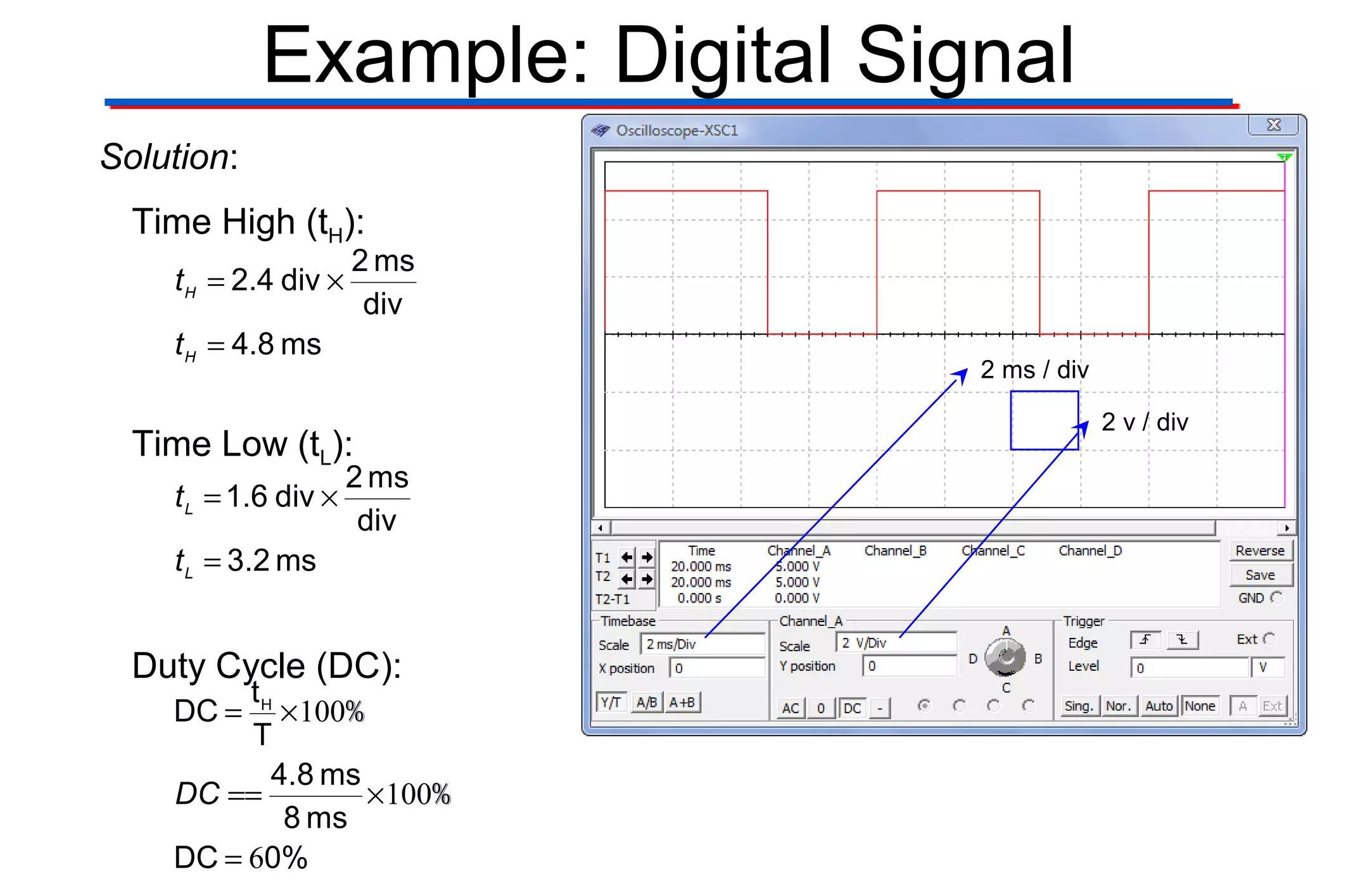
- Period = 1 ms
- High time = 0.25 ms
- PWM motor control.
- LED brightness control.
- Servo-related signals.
- Switching circuits.
- Power electronics.
- Digital control systems.
Measuring Rise and Fall Time
- Rise time describes how quickly a signal transitions from low to high.
- Fall time describes how quickly it transitions from high to low.
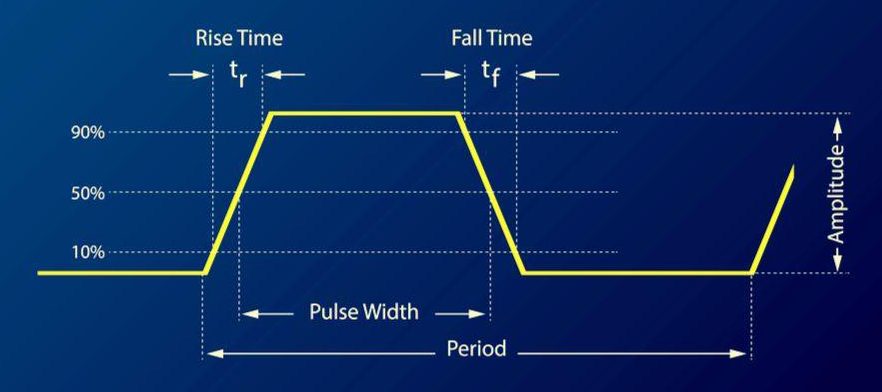
For conventional pulse measurements, rise time is commonly measured between the 10% and 90% levels of the signal amplitude.
Rise and fall time are important when analyzing digital circuits because slow or very fast transitions can create signal-integrity and electromagnetic-interference problems.
Using Cursors and Automatic Measurements
Cursors
Cursors allow you to make manual measurements directly on the waveform.
Voltage cursors measure voltage differences:
ΔV = V₂ − V₁
They can be used for amplitude, offset, and threshold measurements.
Time cursors measure time differences:
ΔT = T₂ − T₁
They can be used for period, pulse width, delay, and transition measurements.

Automatic Measurements
Modern digital oscilloscopes can automatically measure:
- Frequency.
- Period.
- Vpp.
- Vmax.
- Vmin.
- RMS voltage.
- Rise time.
- Fall time.
- Pulse width.
- Duty cycle.
Automatic measurements are convenient, but always check the waveform and measurement setup before trusting the displayed value.
Check:
- Waveform display.
- Trigger stability.
- Probe configuration.
- Signal clipping.
- Measurement location.
Acquisition Modes and Single Trigger
Digital oscilloscopes use acquisition systems to collect and process waveform samples.

Common modes include:
Normal Acquisition
Used for general waveform viewing and repetitive signals.
Average Acquisition
Combines multiple acquisitions to reduce random noise. It can improve waveform clarity but may hide single-occurrence events.
Peak Detect
Helps capture narrow peaks or minimum/maximum excursions that might otherwise be missed.
High-Resolution Acquisition
Some oscilloscopes provide a high-resolution mode that can improve effective vertical resolution for suitable signals.
Single Acquisition
Single acquisition is useful for events that occur only once or infrequently.
Typical procedure:
- Set the trigger condition.
- Arm the oscilloscope.
- Wait for the event.
- Capture the waveform.
- Examine the result.
It is useful for startup behavior, switching transients, glitches, reset events, and fault conditions.
Bandwidth, Sampling Rate, and Memory Depth
These specifications are important when selecting or evaluating a digital oscilloscope.
Bandwidth
Oscilloscope bandwidth indicates the frequency range over which the instrument can accurately measure signals. It is commonly specified at the −3 dB point.
Insufficient bandwidth can attenuate high-frequency components and make fast square-wave edges appear rounded.
Sample Rate
Sample rate describes how frequently the oscilloscope samples the input signal.
It is commonly specified in:
S/s, MSa/s, or GSa/s.
A higher sample rate provides more samples and can help preserve fast signal details. However, accurate real-world measurements require more than simply meeting the basic Nyquist minimum.

Memory Depth
Memory depth is the number of samples that can be stored during an acquisition.
Greater memory depth allows the oscilloscope to capture a longer time interval while maintaining a high sample rate.
A simple way to remember these specifications is:
- Bandwidth → How fast a signal the scope can accurately pass.
- Sample rate → How frequently the signal is sampled.
- Memory depth → How many samples can be stored.
Common Beginner Mistakes
- Incorrect Probe Setting: If the probe is set to 10X but the oscilloscope is configured for 1X, the displayed voltage can be incorrect.
- Poor Probe Compensation: An improperly compensated probe can distort fast waveform edges.
- Incorrect Ground Connection: A wrong ground connection can produce incorrect measurements or create a dangerous short circuit.
- Long Ground Lead: A long ground lead can introduce ringing and measurement artifacts.
- Incorrect V/div: Too large a value can make small details difficult to see, while too small a value can clip the waveform.
- Incorrect Time/div: Too large a value can hide fast details, while too small a value may show too little of a slow waveform.
- Incorrect Trigger: An incorrect source, level, edge, or mode can make the waveform appear unstable.
- Insufficient Bandwidth: The waveform may appear clean while still being inaccurate if the oscilloscope or probe lacks sufficient bandwidth.
- Exceeding Probe Ratings: Always check the voltage, frequency, category, and other applicable ratings before measuring.
- Trusting Automatic Measurements: A numerical result is meaningful only when the waveform and measurement setup are correct.
Practical Oscilloscope Examples
Example 1: Measuring a DC Power Supply
For a nominal 5 V supply:
- Select DC coupling.
- Connect the probe ground to the appropriate circuit ground.
- Connect the probe tip to the 5 V output.
- Select a suitable V/div setting.
- Adjust Time/div.
- Set a stable trigger.
- Measure the DC level.
- Look for ripple, noise, or spikes.
A multimeter may show approximately 5 V, while the oscilloscope can reveal variations around that value.
Example 2: Measuring a 555 Timer
Connect the probe to the 555 output and circuit ground.
Then:
- Adjust V/div.
- Adjust Time/div.
- Set an edge trigger.
- Measure Vpp.
- Measure period.
- Calculate frequency.
- Measure duty cycle if required.
This provides practice with several basic oscilloscope functions.
Example 3: Measuring PWM
Connect the probe to the PWM output and observe:
- Frequency.
- Period.
- High time.
- Low time.
- Duty cycle.
- Rise time.
- Fall time.
Changing the duty cycle changes the proportion of each cycle during which the signal remains high.
Basic Oscilloscope Troubleshooting
| Problem | Possible Cause | What to Check |
|---|---|---|
| No waveform appears. | Incorrect connection. | Check probe tip, ground, and channel selection. |
| Waveform is too small. | V/div is too large. | Reduce V/div. |
| Waveform is clipped. | V/div is too small. | Increase V/div. |
| Waveform moves continuously. | Incorrect triggering. | Check trigger source, edge, level, and mode. |
| Waveform looks distorted. | Probe or bandwidth problem. | Check compensation and bandwidth. |
| Square wave has rounded edges. | Insufficient bandwidth. | Check oscilloscope and probe bandwidth. |
| Waveform is very noisy. | Circuit noise or measurement setup. | Check grounding and probe connection. |
| Unexpected ringing appears. | Long ground lead or probing artifact. | Use a shorter ground connection. |
| Voltage reading is wrong. | Probe attenuation mismatch. | Check 1X/10X settings. |
| DC level appears missing. | AC coupling selected. | Switch to DC coupling when appropriate. |
| One-time event is missed. | Incorrect trigger or acquisition. | Use Single acquisition and a suitable trigger. |
| Frequency reading is unstable. | Poor triggering or noisy signal. | Improve triggering and probe connection. |
A useful troubleshooting sequence is:
Probe → Connection → V/div → Time/div → Trigger → Measurement.
Frequently Asked Questions
Is using an oscilloscope difficult?
The basic controls can be learned relatively quickly. However, developing confidence with probing, triggering, signal integrity, and advanced measurements requires practice.
What should I measure first?
Start with the oscilloscope’s built-in calibration signal. It provides a known waveform for practicing probe connection, compensation, scaling, and triggering.
Why does my waveform look noisy?
Check the probe ground connection, ground-lead length, probe compensation, coupling, and signal integrity. Measurement setup can introduce noise and artifacts.
Why is my square wave rounded?
A rounded square wave can result from insufficient oscilloscope or probe bandwidth because the higher-frequency components of the fast edges are being attenuated.
How do I know if my oscilloscope is fast enough?
Check the bandwidth and sample-rate specifications, as well as the probe specifications. For digital signals, edge speed is often more important than the nominal repetition frequency.
Can a multimeter replace an oscilloscope?
Not completely. A multimeter is excellent for steady measurements such as DC voltage, resistance, and continuity. An oscilloscope shows how voltage changes over time, so the two instruments complement each other.
Can an oscilloscope measure current?
An oscilloscope normally measures voltage directly. Current can be measured indirectly using a suitable current probe, current transformer, or shunt resistor, provided the method is appropriate and safe.
What is the difference between frequency and period?
Period is the time required for one complete cycle, while frequency is the number of cycles per second.
f = 1/T
What is Single Acquisition used for?
It is used to capture events that occur once or infrequently, such as startup transients, glitches, reset pulses, and fault conditions.
Should I always use AUTOSET?
AUTOSET is useful for quickly obtaining a waveform, especially for beginners. However, learning V/div, Time/div, coupling, and triggering manually is essential for troubleshooting.
Conclusion
Learning to use an oscilloscope is an important skill for anyone working with electronics. Unlike an instrument that provides only a numerical value, an oscilloscope allows you to see how an electrical signal behaves over time.
The basic workflow is:
Probe → V/div → Time/div → Trigger → Measurement → Analysis.
Start by understanding the display, then learn proper probe connection and compensation, 1X/10X operation, AC/DC coupling, and safe grounding.
Once you can obtain a stable waveform, practice measuring voltage, period, frequency, pulse width, duty cycle, rise time, and fall time. Then progress to cursors, automatic measurements, acquisition modes, and single-event capture.
Most importantly, remember that the waveform on the screen is only useful when it accurately represents the circuit. Incorrect probing, grounding, bandwidth, sampling, triggering, or instrument settings can create misleading results.
With regular hands-on practice, an oscilloscope becomes an intuitive and powerful tool for electronics design, testing, repair, and troubleshooting.
الأوسيلوسكوب خطوة بخطوة
قائمة المحتويات
- المقدمة.
- ما هو الأوسيلوسكوب؟
- فهم شاشة الأوسيلوسكوب.
- فهم V/div و Time/div.
- فهم التزامن (Triggering).
- فهم مجسات الأوسيلوسكوب.
- مجسات 1X و10X.
- معايرة المجس (Probe Compensation).
- الاقتران AC وDC.
- كيفية توصيل الأوسيلوسكوب بأمان؟
- الإعداد الأول للأوسيلوسكوب — خطوة بخطوة.
- قياس الجهد.
- قياس التردد والزمن الدوري.
- قياس عرض النبضة ونسبة التشغيل.
- قياس زمن الصعود والهبوط.
- استخدام المؤشرات والقياسات التلقائية.
- أنماط الالتقاط والتشغيل الأحادي.
- عرض النطاق ومعدل أخذ العينات وعمق الذاكرة.
- أخطاء المبتدئين الشائعة.
- أمثلة عملية على استخدام الأوسيلوسكوب.
- استكشاف الأعطال الأساسية في الأوسيلوسكوب.
- الأسئلة الشائعة.
- الخلاصة.
زمن القراءة حوالي : 20 دقيقة.
المقدمة
هل سبق أن واجهت مشكلة أثناء فحص دائرة إلكترونية واحتجت إلى معلومات أكثر مما يستطيع جهاز الملتيميتر العادي إظهارها؟ عند الحاجة إلى فهم الإشارات الكهربائية بالتفصيل، يمكن استخدام الأوسيلوسكوب لمراقبة الإشارات، وقياس التوقيت، وتحليل إشارات PWM والنبضات الرقمية، وفحص تموجات مصادر التغذية، وتحديد أعطال الدوائر.
يُعد تعلم استخدام الأوسيلوسكوب مهارة أساسية لكل من يعمل في مجال الإلكترونيات، سواء كان طالبًا أو هاويًا أو مهندسًا محترفًا. فهو يتيح لك رؤية الإشارة الكهربائية أثناء تغيرها مع الزمن، وهو أمر مهم عند تشخيص سبب عدم عمل دائرة المؤقت 555 بالشكل المتوقع، أو عند البحث عن أسباب التشويه والضوضاء في الدائرة.
قد يواجه كثير من المستخدمين شاشة غير مستقرة، أو إعدادات Trigger مربكة، أو قياسات لا تتوافق مع التوقعات. وقد تؤدي هذه المشكلات إلى إبطاء عملية التطوير أو إلى استنتاجات غير صحيحة.
عندما تتعلم ضبط الأوسيلوسكوب واستخدامه بشكل صحيح، تصبح عملية اكتشاف الأعطال أسرع، وتتحسن قرارات التصميم، وتقل احتمالية إضاعة الوقت في البحث عن مشكلات غير موجودة فعليًا. كما تساعدك الخبرة الجيدة في استخدامه على تشخيص الضوضاء ومشكلات التوقيت والتشويه بثقة أكبر.
تتوفر أجهزة الأوسيلوسكوب بإصدارات تعمل من مصدر كهرباء مباشر أو بالبطارية، كما تتوفر بأحجام مختلفة. وتكون الأجهزة الصغيرة التي تعمل بالبطارية مناسبة بشكل خاص للاستخدام الميداني والتنقل. وبعض الأجهزة تجمع بين وظائف الأوسيلوسكوب والملتيميتر، مما يوفر قراءة رقمية للإشارة إلى جانب عرض شكلها، وقد تكون مناسبة في بعض التطبيقات كبديل عملي عن استخدام جهازين منفصلين.
يقدم هذا الدليل شرحًا عمليًا لاستخدام الأوسيلوسكوب خطوة بخطوة، بدءًا من فهم الشاشة وتوصيل المجس، وصولًا إلى إجراء القياسات وتشخيص المشكلات الشائعة، بحيث تتمكن من قراءة الإشارات وفهم سلوك الدوائر الإلكترونية بكفاءة.
ما هو الأوسيلوسكوب؟
الأوسيلوسكوب، ويُعرف أيضًا باسم Scope أو O-Scope، هو جهاز قياس إلكتروني يعرض الإشارة الكهربائية على شكل موجة، مما يسمح بمراقبة تغيرها مع الزمن.
يعتمد المبدأ الأساسي على عرض الجهد على المحور الرأسي والزمن على المحور الأفقي.
وبذلك يمكنك رؤية كيفية تغير الإشارة بدلًا من الحصول على قيمة رقمية واحدة فقط.
يمكن للأوسيلوسكوب عرض أنواع مختلفة من الإشارات، منها:
- إشارات الجهد المستمر والمتردد.
- الموجات الجيبية.
- الموجات المربعة.
- النبضات وإشارات PWM.
- الإشارات الرقمية.
- إشارات الصوت والحساسات.
- تموجات مصادر التغذية.
- الضوضاء والتداخل.
- القمم العابرة والنبضات غير المرغوبة.
قد يخبرك الملتيميتر بأن جهد الدائرة يبلغ 5 V، بينما يستطيع الأوسيلوسكوب أن يوضح ما إذا كان هذا الجهد ثابتًا أو يحتوي على ضوضاء أو تموجات أو قمم غير مرغوبة.
فهم شاشة الأوسيلوسكوب
تعتمد شاشة الأوسيلوسكوب على شبكة قياس تُعرف باسم Graticule، وهي التي تساعد على قراءة الجهد والزمن من شكل الموجة.
المحور الرأسي — الجهد
يمثل المحور الرأسي أو محور Y قيمة الجهد.
ويحدد إعداد V/div مقدار الجهد الذي تمثله كل خانة رأسية.
مثال: عند ضبط الجهاز على 2 V/div وتغطية الموجة لثلاث خانات رأسية:
Vpp = 3 × 2 V = 6 V
المحور الأفقي — الزمن
يمثل المحور الأفقي أو محور X الزمن.
ويحدد إعداد Time/div مقدار الزمن الذي تمثله كل خانة أفقية.
مثال: إذا كانت دورة كاملة تشغل أربع خانات عند ضبط الجهاز على 1 ms/div:
T = 4 × 1 ms = 4 ms
ويكون التردد:
f = 1/T = 1/0.004 = 250 Hz
القنوات
تسمح أجهزة الأوسيلوسكوب متعددة القنوات بعرض أكثر من إشارة في الوقت نفسه. وتفيد هذه الخاصية في مقارنة الإشارات ودراسة العلاقة الزمنية بينها.
فهم V/div وTime/div
يُعد كل من V/div وTime/div من أهم إعدادات الأوسيلوسكوب التي يجب على المبتدئ فهمها.
V/div
يتحكم V/div في المقياس الرأسي للجهد.
- قلل قيمة V/div عندما تكون الموجة صغيرة جدًا على الشاشة.
- زد قيمة V/div عندما تكون الموجة كبيرة جدًا أو تتجاوز حدود الشاشة.
الهدف هو جعل الموجة واضحة وكبيرة بما يكفي لفحصها دون أن تتعرض للقص.
توضيح عملي لمقياسي V/div وTime/div على شاشة الأوسيلوسكوب.
Time/div
يتحكم Time/div في المقياس الأفقي للزمن.
- استخدم قيمة زمنية أصغر لفحص الإشارات السريعة.
- استخدم قيمة زمنية أكبر لمراقبة الإشارات التي تتغير ببطء.
ويحدد هذان الإعدادان معًا مقدار الإشارة الذي يظهر على الشاشة وطريقة عرضها.
فهم التزامن (Triggering)
يحدد Trigger للأوسيلوسكوب النقطة المناسبة في الإشارة التي يعتمد عليها الجهاز كمرجع زمني لعرض الموجة.
من دون ضبط Trigger بشكل صحيح، قد تبدو الموجة المتكررة وكأنها تتحرك باستمرار أو تكون غير مستقرة على الشاشة.
إعدادات Trigger الأساسية: مصدر التزامن ومستوى التزامن والحافة الصاعدة أو الهابطة
مصدر Trigger
يحدد القناة التي يستخدمها الأوسيلوسكوب للحصول على إشارة التزامن، مثل CH1.
مستوى Trigger
يحدد مستوى الجهد الذي يعتبره الأوسيلوسكوب نقطة مناسبة لبدء عرض الموجة.
حافة Trigger
يمكن للأوسيلوسكوب عادةً أن يبدأ التزامن عند:
- الحافة الصاعدة.
- الحافة الهابطة.
وضع Trigger
تشمل الأوضاع الشائعة:
- Auto.
- Normal.
- Single.
يُعد Auto نقطة بداية مناسبة للمبتدئين. ويوفر Normal تحكمًا أكبر في عملية التزامن، بينما يستخدم Single لالتقاط الأحداث التي تحدث مرة واحدة أو بشكل غير متكرر.
فهم مجسات الأوسيلوسكوب
يربط المجس الأوسيلوسكوب بالدائرة المراد فحصها. ويمكن لمقاومة المجس وسعته وتوهينه وعرض نطاقه وطريقة تأريضه أن تؤثر في نتيجة القياس.
يتكون المجس السلبي التقليدي من:
- رأس المجس: يتصل بنقطة الإشارة المراد قياسها.
- مشبك التأريض: يتصل بالمرجع المناسب في الدائرة.
عند قياس الإشارات السريعة، استخدم أقصر توصيل أرضي عملي. فقد يؤدي سلك التأريض الطويل إلى إضافة حث غير مرغوب فيه وظهور رنين أو تشوهات ناتجة عن طريقة القياس.
أجزاء مجس الأوسيلوسكوب: رأس المجس ومشبك التأريض
مجسات 1X و10X
تحتوي العديد من المجسات السلبية على وضعي 1X و10X.
مجس 1X
- لا يسبب توهينًا يُذكر للإشارة.
- يوفر حساسية أعلى للإشارات الصغيرة.
- عادةً ما يقدم سعة دخل أكبر على الدائرة.
مجس 10X
- يخفض الإشارة بنسبة تقارب 10:1.
- يقلل تحميل الدائرة.
- يُستخدم عادةً في القياسات العامة.
مثال: إذا كان الجهد عند رأس المجس 10 V، فسيصل إلى دخل الأوسيلوسكوب بقيمة تقارب 1 V عند استخدام وضع 10X.
للاستخدامات العامة، يكون 10X غالبًا نقطة بداية جيدة، بشرط أن تكون مواصفات الجهد والتردد والقياس مناسبة.
تأكد دائمًا من أن إعداد المجس في الأوسيلوسكوب يطابق الوضع الفعلي للمفتاح الموجود على المجس.
مقارنة بين مجس 1X ومجس 10X من حيث التوهين وتأثير التحميل على الدائرة
معايرة المجس (Probe Compensation)
يجب عادةً تعويض المجسات السلبية بحيث تتوافق خصائصها مع دخل الأوسيلوسكوب.
توفر معظم أجهزة الأوسيلوسكوب إشارة مربعة مدمجة يمكن استخدامها لمعايرة المجس.
خطوات المعايرة الأساسية
- وصل المجس بالقناة CH1.
- وصل رأس المجس بخَرْج إشارة المعايرة.
- وصل مشبك التأريض بالطرف الأرضي المقابل.
- اعرض الموجة المربعة على الشاشة.
- اضبط مسمار تعويض المجس.
- توقف عند الحصول على زوايا موجة صحيحة وواضحة.
يمكن أن يؤدي سوء تعويض المجس إلى ظهور حواف مستديرة أو Overshoot أو Undershoot في الموجة.
معايرة مجس الأوسيلوسكوب باستخدام إشارة المعايرة المربعة
الاقتران AC وDC
يحدد اقتران دخل الأوسيلوسكوب ما إذا كان المكون المستمر DC للإشارة سيظهر على الشاشة أم سيتم حجبه.
الاقتران DC
- يعرض مستوى DC مع التغيرات المترددة AC في الوقت نفسه.
- على سبيل المثال، يمكن مراقبة مصدر 12 V DC مع تموجاته حول مستوى 12 V الفعلي.
الاقتران AC
- يحجب المكون المستمر DC ويجعل التغيرات المترددة الصغيرة أسهل في الملاحظة.
- يمكن أن يكون مفيدًا عند فحص تموج صغير على مصدر تغذية 12 V.
في القياسات العامة، يكون الاقتران DC عادةً أفضل نقطة بداية.
مقارنة بين عرض الإشارة باستخدام الاقتران DC والاقتران AC
كيفية توصيل الأوسيلوسكوب بأمان؟
السلامة أمر أساسي قبل إجراء أي قياس باستخدام الأوسيلوسكوب.
احرص دائمًا على:
- تقدير الجهد المتوقع قبل التوصيل.
- التحقق من تصنيف دخل الأوسيلوسكوب.
- التحقق من تصنيف الجهد للمجس.
- التحقق من فئة القياس المناسبة عند الحاجة.
- استخدام نسبة التوهين الصحيحة للمجس.
- فهم نقطة اتصال أرضي الأوسيلوسكوب بالدائرة.
- عدم افتراض أن مشبك تأريض المجس معزول كهربائيًا.
تحذير مهم بشأن التأريض
في كثير من أجهزة الأوسيلوسكوب المكتبية، يكون تأريض المجس القياسي متصلًا بالأرضي الوقائي للجهاز. وقد يؤدي توصيله بنقطة غير مناسبة إلى حدوث قصر كهربائي أو تلف الجهاز أو التعرض لخطر كهربائي خطير.
لا توصل مجسًا قياسيًا مؤرضًا مباشرةً عبر مصدر كهرباء رئيسي أو دائرة عائمة وعالية الطاقة، إلا إذا كنت تستخدم معدات وطريقة قياس مناسبة ومصنفة لهذا الغرض ولديك التدريب اللازم.
عند إجراء قياسات خطرة، استخدم مجسات تفاضلية أو معدات قياس معزولة ومصنفة بشكل مناسب عندما يكون ذلك مطلوبًا.
توصيل مجس الأوسيلوسكوب بطريقة صحيحة وآمنة مع الانتباه إلى نقطة التأريض.
الإعداد الأول للأوسيلوسكوب — خطوة بخطوة
لإجراء أول قياس، اتبع التسلسل الأساسي التالي:
- شغّل الأوسيلوسكوب.
- اختر Default Setup أو استخدم AUTOSET للحصول على إعداد أولي مناسب.
- فعّل القناة CH1.
- وصل رأس المجس بالإشارة المراد قياسها.
- وصل أرضي المجس بالمرجع المناسب في الدائرة.
- تحقق من إعداد توهين المجس.
- اضبط V/div.
- اضبط Time/div.
- اضبط مصدر Trigger والحافة والمستوى والوضع.
- استخدم المؤشرات أو القياسات التلقائية لفحص الإشارة.
يُعد AUTOSET مفيدًا للحصول على موجة بسرعة، لكن تعلم التحكم اليدوي في الإعدادات مهم جدًا عند تشخيص الأعطال.
قياس الجهد
تشمل قياسات الجهد الشائعة باستخدام الأوسيلوسكوب:
- Vmax.
- Vmin.
- Vpp.
- Vp.
- Vrms.
العلاقة الأساسية للقياس اليدوي هي:
الجهد = عدد الخانات الرأسية × V/div
إذا غطت الموجة أربع خانات عند ضبط الجهاز على 1 V/div:
Vpp = 4 × 1 V = 4 V
وإذا كانت الموجة متمركزة حول الصفر:
Vp ≈ 2 V
قياس الزمن الدوري والتردد
- الزمن الدوري (T): الزمن اللازم لإكمال دورة واحدة.
- التردد (f): عدد الدورات التي تحدث في الثانية.
العلاقة بينهما:
f = 1/T
لقياس الزمن الدوري يدويًا:
- اعرض موجة متكررة ومستقرة.
- اختر إعداد Time/div مناسبًا.
- حدد دورة كاملة واحدة.
- احسب عدد الخانات الأفقية التي تشغلها الدورة.
- اضرب العدد في قيمة Time/div.
مثال:
4 خانات × 1 ms/div = 4 ms
وبالتالي:
f = 1/4 ms = 250 Hz
قياس عرض النبضة ونسبة التشغيل
تُستخدم هذه القياسات بشكل خاص مع الإشارات الرقمية وإشارات PWM.
عرض النبضة
عرض النبضة هو المدة الزمنية التي تبقى خلالها النبضة عند مستوى محدد، وغالبًا يكون المقصود مدة بقائها في المستوى المرتفع.
نسبة التشغيل (Duty Cycle)
نسبة التشغيل هي النسبة المئوية من الدورة التي تبقى فيها الإشارة عند المستوى المرتفع.
نسبة التشغيل (%) = (عرض النبضة ÷ الزمن الدوري) × 100
مثال:
الزمن الدوري = 1 ms
الزمن المرتفع = 0.25 ms
Duty Cycle = (0.25/1) × 100 = 25%
تُستخدم نسبة التشغيل في العديد من التطبيقات، منها:
- التحكم في محركات PWM.
- التحكم في سطوع LED.
- الإشارات المستخدمة مع المؤازرات Servo.
- دوائر التبديل.
- إلكترونيات القدرة.
- أنظمة التحكم الرقمية.
قياس زمن الصعود والهبوط
- زمن الصعود: يوضح سرعة انتقال الإشارة من المستوى المنخفض إلى المستوى المرتفع.
- زمن الهبوط: يوضح سرعة انتقال الإشارة من المستوى المرتفع إلى المستوى المنخفض.
في القياسات التقليدية للنبضات، يتم عادةً تحديد زمن الصعود بين مستويي 10% و90% من سعة الإشارة.
تُعد أزمنة الصعود والهبوط مهمة عند تحليل الدوائر الرقمية، لأن الانتقالات البطيئة جدًا أو السريعة جدًا قد تؤثر في سلامة الإشارة وتزيد من مشكلات التداخل الكهرومغناطيسي.
استخدام المؤشرات والقياسات التلقائية
المؤشرات (Cursors)
تسمح المؤشرات بإجراء قياسات يدوية مباشرة على الموجة المعروضة.
مؤشرات الجهد تقيس فرق الجهد:
ΔV = V₂ − V₁
ويمكن استخدامها لقياس السعة والإزاحة ومستويات العتبة.
مؤشرات الزمن تقيس الفرق الزمني:
ΔT = T₂ − T₁
ويمكن استخدامها لقياس الزمن الدوري وعرض النبضة والتأخير وزمن الانتقال.
القياسات التلقائية
تستطيع أجهزة الأوسيلوسكوب الرقمية الحديثة إجراء العديد من القياسات تلقائيًا، مثل:
- التردد.
- الزمن الدوري.
- Vpp.
- Vmax.
- Vmin.
- جهد RMS.
- زمن الصعود.
- زمن الهبوط.
- عرض النبضة.
- نسبة التشغيل.
تسهل القياسات التلقائية العمل، ولكن يجب دائمًا فحص الموجة وإعدادات القياس قبل الاعتماد على القيمة المعروضة.
تحقق من:
- شكل الموجة.
- استقرار Trigger.
- إعداد المجس.
- وجود قص في الإشارة.
- مكان إجراء القياس.
استخدام مؤشرات الجهد والزمن والقياسات التلقائية على شاشة الأوسيلوسكوب
أنماط الالتقاط والتشغيل الأحادي
تستخدم أجهزة الأوسيلوسكوب الرقمية أنظمة الالتقاط لجمع عينات الإشارة ومعالجتها وعرضها.
الالتقاط العادي (Normal)
يُستخدم لمراقبة الإشارات العامة والموجات المتكررة.
الالتقاط بالمتوسط (Average)
يجمع عدة عمليات التقاط لتقليل الضوضاء العشوائية وتحسين وضوح الموجة، لكنه قد يخفي الأحداث التي تحدث مرة واحدة.
اكتشاف القمم (Peak Detect)
يساعد على التقاط القمم الضيقة أو أقصى وأدنى قيم الإشارة التي قد لا تظهر بوضوح في أوضاع الالتقاط الأخرى.
الالتقاط عالي الدقة (High Resolution)
توفر بعض الأجهزة وضعًا عالي الدقة يمكن أن يحسن الدقة الرأسية الفعلية عند استخدامه مع الإشارات المناسبة.
الالتقاط الأحادي (Single Acquisition)
يُستخدم لالتقاط الأحداث التي تحدث مرة واحدة أو بشكل غير متكرر.
الخطوات المعتادة:
- حدد شرط Trigger.
- فعّل وضع الالتقاط أو جهّز الجهاز للانتظار.
- انتظر حدوث الحدث.
- التقط الموجة.
- افحص النتيجة.
يفيد هذا الوضع في مراقبة سلوك بدء التشغيل، والانتقالات العابرة، والنبضات غير المرغوبة، وإشارات Reset، وحالات الأعطال.
عرض النطاق ومعدل أخذ العينات وعمق الذاكرة
تُعد هذه المواصفات من أهم العوامل عند اختيار الأوسيلوسكوب الرقمي أو تقييم قدراته.
عرض النطاق (Bandwidth)
يشير عرض نطاق الأوسيلوسكوب إلى نطاق الترددات التي يستطيع الجهاز قياسها بدقة مناسبة، ويُحدد عادةً عند نقطة −3 dB.
قد يؤدي عدم كفاية عرض النطاق إلى إضعاف المكونات عالية التردد وجعل حواف الموجة المربعة السريعة تبدو مستديرة.
معدل أخذ العينات (Sample Rate)
يصف معدل أخذ العينات عدد المرات التي يأخذ فيها الأوسيلوسكوب عينات من الإشارة خلال الثانية.
ويُعبّر عنه عادةً بالوحدات:
S/s أو MSa/s أو GSa/s
يوفر معدل أخذ عينات أعلى عددًا أكبر من العينات، مما يساعد على الحفاظ على تفاصيل الإشارات السريعة. ومع ذلك، فإن القياسات الواقعية الدقيقة تحتاج إلى أكثر من مجرد تحقيق الحد الأدنى النظري لمعيار Nyquist.
عمق الذاكرة (Memory Depth)
يشير عمق الذاكرة إلى عدد العينات التي يستطيع الجهاز تخزينها أثناء عملية الالتقاط.
يسمح عمق الذاكرة الأكبر بالتقاط فترة زمنية أطول مع الحفاظ على معدل أخذ عينات مرتفع.
يمكن تذكر هذه المواصفات بطريقة بسيطة:
- Bandwidth: مدى سرعة الإشارة التي يستطيع الجهاز قياسها بدقة.
- Sample Rate: عدد المرات التي يتم فيها أخذ عينات من الإشارة.
- Memory Depth: عدد العينات التي يستطيع الجهاز تخزينها.
أخطاء المبتدئين الشائعة
- إعداد المجس غير صحيح: إذا كان المجس مضبوطًا على 10X بينما الأوسيلوسكوب مضبوط على 1X، فقد تظهر قيمة الجهد بشكل غير صحيح.
- تعويض المجس غير صحيح: يمكن أن يؤدي تعويض المجس بطريقة غير صحيحة إلى تشويه حواف الإشارات السريعة.
- توصيل التأريض بشكل خاطئ: قد يؤدي توصيل الأرضي بنقطة غير مناسبة إلى قياسات خاطئة أو إلى حدوث قصر خطير.
- استخدام سلك تأريض طويل: قد يؤدي إلى ظهور رنين وتشوهات ناتجة عن طريقة القياس.
- إعداد V/div غير مناسب: القيمة الكبيرة جدًا قد تخفي التفاصيل الصغيرة، بينما القيمة الصغيرة جدًا قد تؤدي إلى قص الموجة.
- إعداد Time/div غير مناسب: القيمة الكبيرة جدًا قد تخفي التفاصيل السريعة، بينما القيمة الصغيرة جدًا قد تعرض جزءًا صغيرًا من الإشارة البطيئة.
- Trigger غير صحيح: يمكن أن يؤدي اختيار مصدر أو مستوى أو حافة أو وضع غير مناسب إلى ظهور الموجة بشكل غير مستقر.
- عرض نطاق غير كافٍ: قد تبدو الموجة نظيفة رغم أن شكلها غير دقيق إذا كان عرض نطاق الجهاز أو المجس غير كافٍ.
- تجاوز حدود المجس: تحقق دائمًا من تصنيفات الجهد والتردد وفئة القياس وغيرها من التصنيفات المناسبة قبل إجراء القياس.
- الاعتماد الكامل على القياسات التلقائية: لا تكون القيمة الرقمية مفيدة إلا إذا كانت الموجة وإعدادات القياس صحيحة.
أمثلة عملية على استخدام الأوسيلوسكوب
المثال الأول: قياس مصدر تغذية DC
عند فحص مصدر تغذية اسمي بقيمة 5 V:
- اختر الاقتران DC.
- وصل أرضي المجس بأرضي الدائرة المناسب.
- وصل رأس المجس بخَرْج 5 V.
- اختر إعداد V/div مناسبًا.
- اضبط Time/div.
- اضبط Trigger مستقرًا.
- قِس مستوى الجهد المستمر.
- ابحث عن التموجات والضوضاء والقمم العابرة.
قد يعرض الملتيميتر قيمة قريبة من 5 V، بينما يستطيع الأوسيلوسكوب إظهار التغيرات الصغيرة حول هذه القيمة.
المثال الثاني: قياس مؤقت 555
وصل المجس بخَرْج دائرة 555 وبأرضي الدائرة.
ثم:
- اضبط V/div.
- اضبط Time/div.
- اختر Trigger على حافة مناسبة.
- قِس Vpp.
- قِس الزمن الدوري.
- احسب التردد.
- قِس نسبة التشغيل عند الحاجة.
يوفر هذا المثال تدريبًا عمليًا على عدد من وظائف الأوسيلوسكوب الأساسية.
المثال الثالث: قياس PWM
وصل المجس بخَرْج PWM وراقب:
- التردد.
- الزمن الدوري.
- الزمن المرتفع.
- الزمن المنخفض.
- نسبة التشغيل.
- زمن الصعود.
- زمن الهبوط.
يؤدي تغيير نسبة التشغيل إلى تغيير الجزء من كل دورة الذي تبقى خلاله الإشارة عند المستوى المرتفع.
استكشاف الأعطال الأساسية في الأوسيلوسكوب
| المشكلة | السبب المحتمل | ما الذي يجب فحصه؟ |
|---|---|---|
| لا تظهر الموجة. | توصيل غير صحيح. | افحص رأس المجس والأرضي واختيار القناة. |
| الموجة صغيرة جدًا. | قيمة V/div كبيرة. | قلل قيمة V/div. |
| الموجة مقصوصة. | قيمة V/div صغيرة. | زد قيمة V/div. |
| الموجة تتحرك باستمرار. | Trigger غير صحيح. | افحص المصدر والحافة والمستوى والوضع. |
| الموجة مشوهة. | مشكلة في المجس أو عرض النطاق. | افحص التعويض وعرض النطاق. |
| الموجة المربعة ذات حواف مستديرة. | عرض نطاق غير كافٍ. | افحص عرض نطاق الجهاز والمجس. |
| الموجة شديدة الضوضاء. | ضوضاء الدائرة أو طريقة القياس. | افحص التأريض وتوصيل المجس. |
| ظهور رنين غير متوقع. | سلك تأريض طويل أو أثر من آثار القياس. | استخدم توصيلًا أرضيًا أقصر. |
| قراءة الجهد غير صحيحة. | عدم تطابق توهين المجس. | افحص إعدادات 1X و10X. |
| مستوى DC غير ظاهر. | تم اختيار AC Coupling. | انتقل إلى DC Coupling عند الحاجة. |
| لم يتم التقاط حدث لمرة واحدة. | Trigger أو Acquisition غير صحيح. | استخدم Single Acquisition واضبط Trigger مناسبًا. |
| قراءة التردد غير مستقرة. | Trigger ضعيف أو إشارة noisy. | حسّن Trigger وتوصيل المجس. |
تسلسل مفيد لاستكشاف المشكلة:
المجس → التوصيل → V/div → Time/div → Trigger → القياس.
الأسئلة الشائعة
هل استخدام الأوسيلوسكوب صعب؟
يمكن تعلم الوظائف الأساسية خلال فترة قصيرة نسبيًا، لكن اكتساب الخبرة في استخدام المجسات وTrigger وسلامة الإشارة والقياسات المتقدمة يحتاج إلى ممارسة عملية.
ما أول إشارة يجب قياسها؟
ابدأ بإشارة المعايرة المدمجة في الأوسيلوسكوب. فهي توفر موجة معروفة تساعدك على التدريب على توصيل المجس وتعويضه وضبط المقياس وTrigger.
لماذا تبدو الموجة مليئة بالضوضاء؟
افحص اتصال أرضي المجس وطول سلك الأرضي وتعويض المجس والاقتران وسلامة الإشارة. فقد تتسبب طريقة القياس نفسها في ظهور ضوضاء أو تشوهات.
لماذا تبدو الموجة المربعة ذات حواف مستديرة؟
قد يحدث ذلك بسبب عدم كفاية عرض نطاق الأوسيلوسكوب أو المجس، حيث يتم إضعاف المكونات عالية التردد المسؤولة عن الحواف السريعة.
كيف أعرف أن الأوسيلوسكوب سريع بما يكفي؟
تحقق من مواصفات عرض النطاق ومعدل أخذ العينات، بالإضافة إلى مواصفات المجس. وفي الإشارات الرقمية، قد يكون زمن الحافة أهم من التردد الاسمي للإشارة.
هل يمكن للملتيميتر أن يحل محل الأوسيلوسكوب؟
ليس بشكل كامل. فالملتيميتر ممتاز للقياسات الثابتة مثل جهد DC والمقاومة والاستمرارية، بينما يوضح الأوسيلوسكوب كيف يتغير الجهد مع الزمن. لذلك يكمل الجهازان بعضهما.
هل يستطيع الأوسيلوسكوب قياس التيار؟
يقيس الأوسيلوسكوب الجهد مباشرةً في الأساس. ويمكن قياس التيار بصورة غير مباشرة باستخدام مجس تيار مناسب أو محول تيار أو مقاومة Shunt، بشرط أن تكون طريقة القياس مناسبة وآمنة.
ما الفرق بين التردد والزمن الدوري؟
الزمن الدوري هو المدة اللازمة لإكمال دورة واحدة، بينما التردد هو عدد الدورات التي تحدث في الثانية.
f = 1/T
ما استخدام Single Acquisition؟
يُستخدم لالتقاط الأحداث التي تحدث مرة واحدة أو نادرًا، مثل انتقالات بدء التشغيل والنبضات غير المرغوبة وإشارات Reset وحالات الأعطال.
هل يجب أن أستخدم AUTOSET دائمًا؟
يُعد AUTOSET مفيدًا للحصول على موجة بسرعة، خاصة للمبتدئين. ومع ذلك، فإن تعلم ضبط V/div وTime/div والاقتران وTrigger يدويًا أمر أساسي لتشخيص الأعطال.
الخلاصة
يُعد تعلم استخدام الأوسيلوسكوب مهارة مهمة لكل من يعمل في مجال الإلكترونيات. وعلى عكس أدوات القياس التي تعرض قيمة رقمية فقط، يسمح لك الأوسيلوسكوب برؤية سلوك الإشارة الكهربائية مع الزمن.
يمكن تلخيص سير العمل الأساسي في:
المجس → V/div → Time/div → Trigger → القياس → التحليل.
ابدأ بفهم الشاشة، ثم تعلم التوصيل الصحيح للمجس وتعويضه، واستخدام 1X و10X، والاقتران AC/DC، والتأريض الآمن.
بعد الحصول على موجة مستقرة، تدرب على قياس الجهد والزمن الدوري والتردد وعرض النبضة ونسبة التشغيل وزمن الصعود والهبوط. ثم انتقل إلى المؤشرات والقياسات التلقائية وأنماط الالتقاط والتقاط الأحداث الفردية.
والأهم من ذلك، تذكر أن الموجة الظاهرة على الشاشة تكون مفيدة فقط عندما تمثل الإشارة الموجودة في الدائرة تمثيلًا صحيحًا. فقد تؤدي أخطاء التوصيل أو التأريض أو عرض النطاق أو أخذ العينات أو Trigger أو إعدادات الجهاز إلى نتائج مضللة.
ومع الممارسة العملية المنتظمة، يصبح الأوسيلوسكوب أداة قوية وسهلة الفهم لتصميم الدوائر الإلكترونية واختبارها وإصلاحها واستكشاف أعطالها.


Leave a comment
You must be logged in to post a comment.