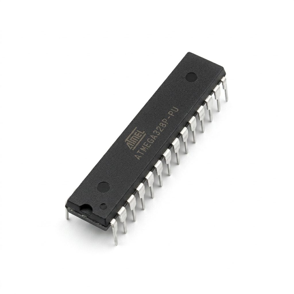
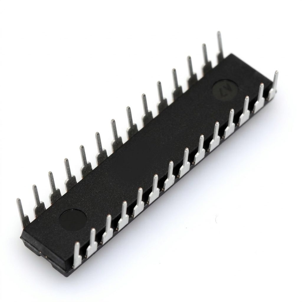


ATmega328P-PU 8-Bit AVR Microcontroller IC 5V PDIP-28 for Arduino Uno (Without Bootloader)
ATmega328P-PU 8-Bit AVR Microcontroller IC 5V PDIP-28 for Arduino Uno (Without Bootloader) is a high-performance, low-power AVR microcontroller widely used in Arduino Uno-compatible designs and embedded control systems. Featuring a 20MHz maximum clock speed, 32KB of Flash memory, 2KB SRAM, and 1KB EEPROM, it provides an excellent balance of performance and efficiency for a wide range of electronic applications. The PDIP-28 package makes it ideal for breadboards, prototyping, educational projects, and custom PCB designs. Since this version is supplied without the Arduino bootloader, it is well suited for users who prefer programming directly using an ISP programmer or wish to install a custom bootloader.
Features
- High-performance 8-bit AVR RISC microcontroller architecture.
- Operates from a single 1.8V to 5.5V supply.
- Compatible with Arduino Uno hardware platform.
- Supplied without bootloader for custom programming.
- Up to 20MHz operating frequency.
- 32KB In-System Programmable Flash memory.
- 2KB SRAM for efficient program execution.
- 1KB EEPROM for non-volatile data storage.
- 23 programmable digital I/O pins.
- Six PWM output channels.
- Six 10-bit ADC channels in the PDIP package.
- Supports UART, SPI, and I²C communication interfaces.
- Low power consumption for battery-powered applications.
- Standard PDIP-28 package suitable for breadboards and sockets.
Specifications
| Parameter | Details |
|---|---|
| Product Type | 8-Bit AVR Microcontroller IC |
| Device Family | AVR Enhanced RISC |
| Model | ATmega328P-PU |
| Package | PDIP-28 |
| Package Type | Through Hole |
| Operating Voltage | 1.8V to 5.5V |
| Maximum Clock Frequency | 20MHz |
| CPU Performance | Up to 20MIPS @20MHz |
| Program Memory | 32KB ISP Flash |
| SRAM | 2KB |
| EEPROM | 1KB |
| General Purpose Registers | 32 × 8-Bit |
| Digital I/O Pins | 23 |
| ADC Channels | 6 |
| ADC Resolution | 10-Bit |
| PWM Channels | 6 |
| Timers / Counters | Two 8-Bit, One 16-Bit |
| Communication Interfaces | USART, SPI, I²C (TWI) |
| External Interrupts | 2 |
| Pin Change Interrupts | 24 |
| Analog Comparator | 1 |
| Watchdog Timer | Programmable |
| Operating Current | Typical 9mA @5V, 16MHz |
| Power Saving Modes | Idle, ADC Noise Reduction, Power-save, Power-down, Standby, Extended Standby |
| Operating Temperature | -40°C to +85°C |
| Programming Method | ISP, High-Voltage Parallel Programming |
| Bootloader Support | Self-Programmable Boot Section |
| Bootloader | Not Installed |
| Arduino Compatibility | Arduino Uno Compatible |
Dimensions
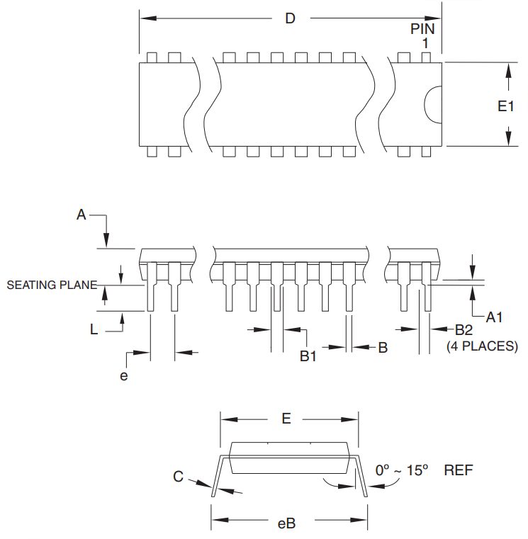
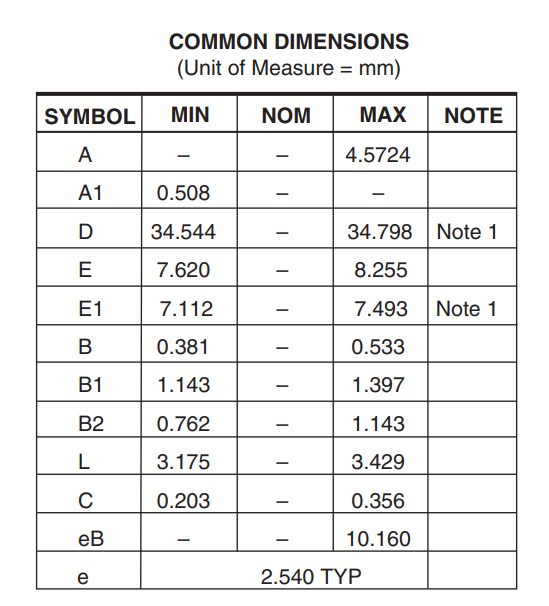
Note 1
- Dimensions D and E1 do not include mold Flash or Protrusion. Mold Flash or Protrusion shall not exceed 0.25 mm (0.010″).
Pin Configuration
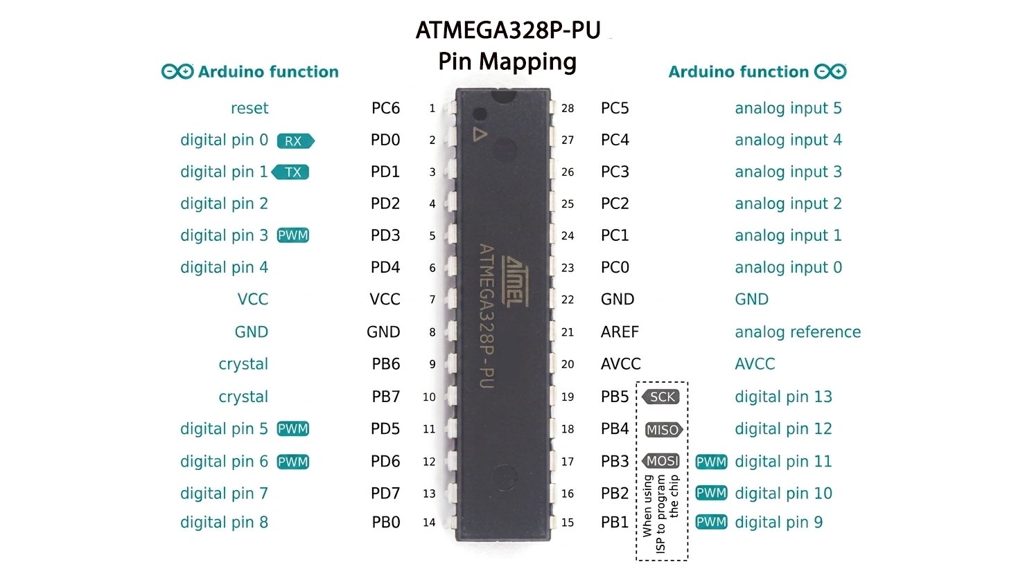
| Pin Number | Pin Name | Function / Description |
|---|---|---|
| 1 | PC6 (RESET) | Reset input. Can also function as PC6 I/O when RESET fuse is disabled. |
| 2 | PD0 (RXD) | Digital Pin D0. UART Receive (RX). |
| 3 | PD1 (TXD) | Digital Pin D1. UART Transmit (TX). |
| 4 | PD2 (INT0) | Digital Pin D2. External Interrupt 0. |
| 5 | PD3 (OC2B / INT1) | Digital Pin D3. PWM Output and External Interrupt 1. |
| 6 | PD4 (T0 / XCK) | Digital Pin D4. Timer0 External Clock / USART Clock. |
| 7 | VCC | Main 5V Power Supply Input. |
| 8 | GND | Ground. |
| 9 | PB6 (XTAL1) | Crystal Oscillator Input. |
| 10 | PB7 (XTAL2) | Crystal Oscillator Output. |
| 11 | PD5 (OC0B) | Digital Pin D5. PWM Output. |
| 12 | PD6 (OC0A / AIN0) | Digital Pin D6. PWM Output / Analog Comparator Input. |
| 13 | PD7 (AIN1) | Digital Pin D7. Analog Comparator Input. |
| 14 | PB0 (ICP1 / CLKO) | Digital Pin D8. Timer1 Input Capture / Clock Output. |
| 15 | PB1 (OC1A) | Digital Pin D9. PWM Output. |
| 16 | PB2 (SS / OC1B) | Digital Pin D10. PWM Output / SPI Slave Select (SS). |
| 17 | PB3 (MOSI / OC2A) | Digital Pin D11. PWM Output / SPI MOSI. |
| 18 | PB4 (MISO) | Digital Pin D12. SPI MISO. |
| 19 | PB5 (SCK) | Digital Pin D13. SPI Clock (SCK). |
| 20 | AVCC | Analog Power Supply for ADC and Port C. |
| 21 | AREF | Analog Reference Voltage for ADC. |
| 22 | GND | Ground. |
| 23 | PC0 (ADC0) | Analog Input A0. |
| 24 | PC1 (ADC1) | Analog Input A1. |
| 25 | PC2 (ADC2) | Analog Input A2. |
| 26 | PC3 (ADC3) | Analog Input A3. |
| 27 | PC4 (ADC4 / SDA) | Analog Input A4 / I²C SDA. |
| 28 | PC5 (ADC5 / SCL) | Analog Input A5 / I²C SCL. |
Connection Block Diagram

Applications
- Arduino Uno compatible projects.
- Embedded control systems.
- Industrial automation controllers.
- Home automation devices.
- Robotics and robotic control systems.
- IoT and smart sensor nodes.
- Data acquisition systems.
- Motor control applications.
- LED lighting and display controllers.
- Environmental monitoring devices.
- Consumer electronic products.
- Educational electronics projects.
- Custom PCB development.
- Battery-powered embedded systems.
- Serial communication interfaces.
Package Contents
- 1 x ATmega328P-PU 8-Bit AVR Microcontroller IC 5V PDIP-28 for Arduino Uno (Without Bootloader)