-
-

-
-

-

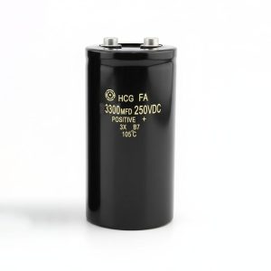
Epcos B43564-S9338-M2 Aluminium Electrolytic Capacitor 3300uF 400V Screw Terminal
1,850.00 EGP1,850.00 EGP× -

-

-

-
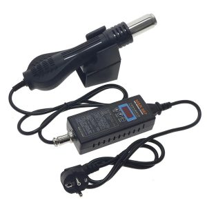


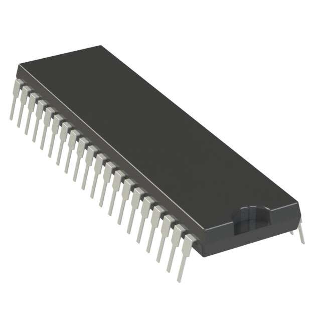
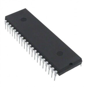
ATMEGA32A-U 8-Bit Microcontroller 32KB 2.7V~5.5V AVR 2KB 16MHz FLASH 32 DIP-40
ATMEGA32A-U 8-Bit AVR Microcontroller (DIP-40). Features 32KB Flash, 2KB SRAM, 1KB EEPROM, 32 I/O pins, and up to 16MHz operation for embedded systems.
230.00 EGP
Buy NowATMEGA32A-U 8-Bit Microcontroller 32KB 2.7V~5.5V AVR 2KB 16MHz FLASH 32 DIP-40
The ATMEGA32A-U 8-Bit Microcontroller 32KB 2.7V~5.5V AVR 2KB 16MHz FLASH 32 DIP-40 is a powerful low-power AVR® RISC microcontroller designed for embedded control, industrial automation, robotics, IoT, and educational development. Based on the AVR enhanced RISC architecture, it executes most instructions in a single clock cycle, delivering processing performance of up to 16MIPS at 16MHz while maintaining excellent power efficiency. Its through-hole DIP-40 package makes it ideal for breadboards, prototyping, development boards, and production designs.
Features:
- High-performance 8-bit AVR RISC architecture.
- Up to 16MIPS throughput at 16MHz.
- 32KB In-System Self-Programmable Flash memory.
- 2KB SRAM and 1KB EEPROM.
- Operating voltage from 2.7V to 5.5V.
- 32 programmable digital I/O pins.
- 8-channel 10-bit ADC.
- USART, SPI, and TWI communication interfaces.
- Three Timer/Counters with PWM outputs.
Specifications:
| Parameter | Value |
|---|---|
| Part Number | ATMEGA32A-U |
| Core Architecture | 8-Bit AVR RISC |
| Package | DIP-40 |
| Mounting Type | Through Hole |
| Operating Voltage | 2.7V~5.5V |
| Maximum Clock Frequency | 16MHz |
| CPU Performance | Up to16MIPS |
| Flash Memory | 32KB |
| SRAM | 2KB |
| EEPROM | 1KB |
| Digital I/O Pins | 32 |
| ADC Resolution | 10-Bit |
| ADC Channels | 8 |
| Timer/Counters | 2×8-Bit,1×16-Bit |
| PWM Channels | 4 |
| USART | 1 |
| SPI | 1 |
| TWI (I²C) | 1 |
| Analog Comparator | 1 |
| External Interrupts | 3 |
| Operating Temperature | -40°C~+85°C |
Pin Configuration:
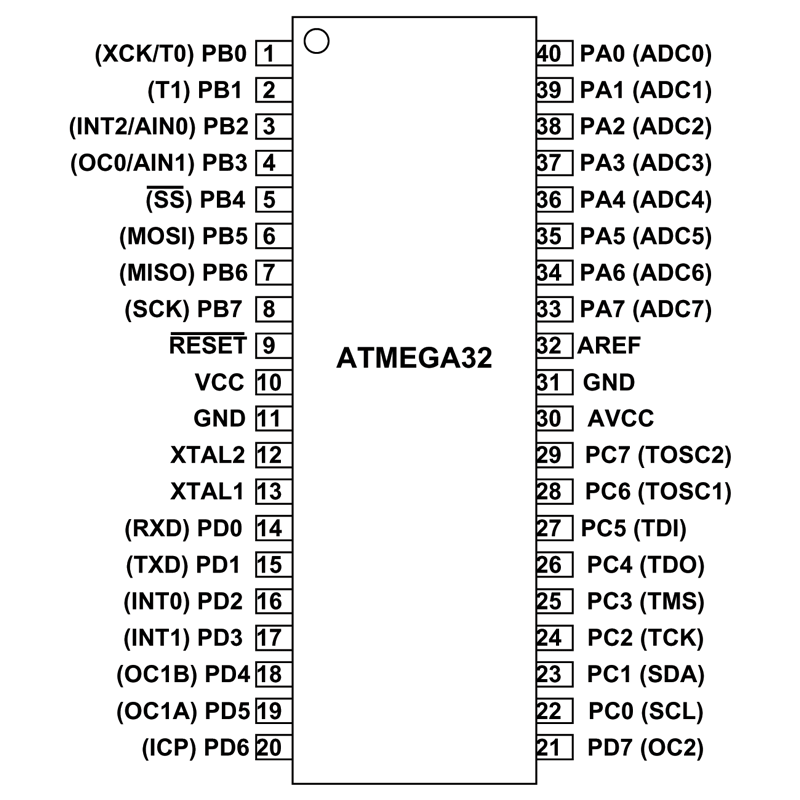
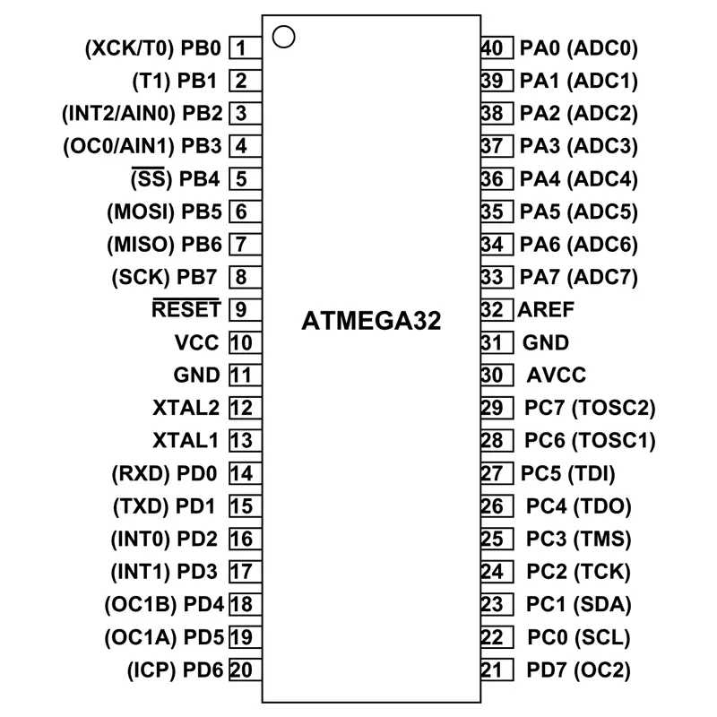
| Pin No. | Pin name | Description | Alternate Function |
| 1 | PB0(XCK/T0) | Pin 0 of PORTB | T0( Timer0 External Counter Input)
XCK ( USART External Clock I/O) |
| 2 | PB1(T1) | Pin 1 of PORTB | T1(Timer1 External Counter Input) |
| 3 | PB2(INT2/AIN0) | Pin 2 of PORTB | AIN0(Analog Comparator Positive I/P)
INT2( External Interrupt 2 Input) |
| 4 | PB3(OC0/AIN1) | Pin 3 of PORTB | AIN1(Analog Comparator Negative I/P)
OC0 (Timer0 Output Compare Match Output) |
| 5 | PB4(SS) | Pin 4 of PORTB | SS (SPI Slave Select Input). This pin is low when controller acts as slave.
[Serial Peripheral Interface (SPI) for programming] |
| 6 | PB5(MOSI) | Pin 5 of PORTB | MOSI (Master Output Slave Input). When controller acts as slave, the data is received by this pin.
[Serial Peripheral Interface (SPI) for programming] |
| 7 | PB6(MISO) | Pin 6 of PORTB | MISO (Master Input Slave Output). When controller acts as slave, the data is sent to master by this controller through this pin.
[Serial Peripheral Interface (SPI) for programming] |
| 8 | PB7(SCK) | Pin 7 of PORTB | SCK (SPI Bus Serial Clock). This is the clock shared between this controller and other system for accurate data transfer.
[Serial Peripheral Interface (SPI) for programming] |
| 9 | RESET | Reset Pin, Active Low Reset | Pulled HIGH to RESET controller. |
| 10 | Vcc | Vcc = +5V | |
| 11 | GND | GROUND | |
| 12 | XTAL2 | Connected to Crystal Oscillator | |
| 13 | XTAL1 | Connected to Crystal Oscillator | |
| 14 | PD0(RXD) | Pin 0 of PORTD | RXD (USART Input Pin)
USART Serial Communication Interface [Can be used for programming] |
| 15 | PD1(TXD) | Pin 1 of PORTD | TXD (USART Output Pin)
USART Serial Communication Interface [Can be used for programming] |
| 16 | PD2(INT0) | Pin 2 of PORTD | External Interrupt INT0 |
| 17 | PD3(INT1) | Pin 3 of PORTD | External Interrupt INT1 |
| 18 | PD4(OC1B) | Pin 4 of PORTD | PWM Channel Outputs |
| 19 | PD5(OC1A) | Pin 5 of PORTD | |
| 20 | PD6(ICP) | Pin 6 of PORTD | Timer/Counter1 Input Capture Pin |
| 21 | PD7 (OC2) | Pin 7 of PORTD | Timer/Counter2 Output Compare Match Output |
| 22 | PC0 (SCL) | Pin 0 of PORTC | TWI Interface |
| 23 | PC1 (SDA) | Pin 1 of PORTC | |
| 24 | PC2 (TCK) | Pin 2 of PORTC | JTAG Interface |
| 25 | PC3 (TMS) | Pin 3 of PORTC | |
| 26 | PC4 (TDO) | Pin 4 of PORTC | |
| 27 | PC5 (TDI) | Pin 5 of PORTC | |
| 28 | PC6 (TOSC1) | Pin 6 of PORTC | Timer Oscillator Pin 1 |
| 29 | PC7 (TOSC2) | Pin 7 of PORTC | Timer Oscillator Pin 2 |
| 30 | AVcc | Vcc for Internal ADC Converter | |
| 31 | GND | GROUND | |
| 32 | AREF | Analog Reference Pin for ADC | |
| 33 | PA7 (ADC7) | Pin 7 of PORTA | ADC (Analog to Digital Converter) Channel 7 |
| 34 | PA6 (ADC6) | Pin 6 of PORTA | ADC (Analog to Digital Converter) Channel 6 |
| 35 | PA5 (ADC5) | Pin 5 of PORTA | ADC (Analog to Digital Converter) Channel 5 |
| 36 | PA4 (ADC4) | Pin 4 of PORTA | ADC (Analog to Digital Converter) Channel 4 |
| 37 | PA3 (ADC3) | Pin 3 of PORTA | ADC (Analog to Digital Converter) Channel 3 |
| 38 | PA2 (ADC2) | Pin 2 of PORTA | ADC (Analog to Digital Converter) Channel 2 |
| 39 | PA1 (ADC1) | Pin 1 of PORTA | ADC (Analog to Digital Converter) Channel 1 |
| 40 | PA0 (ADC0) | Pin 0 of PORTA | ADC (Analog to Digital Converter) Channel 0 |
Where to UseATMEGA32A-U
ATMEGA32 is easy to program AVR controller. With appreciable program memory it can satisfy most EMBEDDED SYSTEMS. With various sleep modes it can work on MOBILE EMBEDDED SYSTEMS. Along with 32 programmable Input/Output pins, it can interface many peripherals easily. With Watchdog timer to reset under error it can be used on systems with no human interference. With so many features with each appreciating other we can implement ATMEGA32 in many control systems.
How to Use ATMEGA32A-U
Using ATMEGA32 is similar to any other microcontroller. Similar to them it is not Plug and Play digital ICs. For working of ATMEGA32, first we need to save the appropriate program file in the ATMEGA32 FLASH memory. After dumping this program code, the controller executes this code to create the response.
Entire process of using an ATMEGA32 goes like this:
- List the functions to be executed by ATMEGA32
- write the functions in IDE programs using relative language
(Usually Atmel Studio 6.2 for Windows7,
Atmel Studio 7 for Windows10 [ https://www.microchip.com/avr-support/atmel-studio-7 ])
(For these IDE the functions should be written in ‘C’ language)
- After writing the desired program compile for error elimination using IDE.
- Opt the IDE application to generate HEX file for the written program.
- Choose the programming device (usually SPI programmer made for AVR controllers) which establishes communication between PC and ATMEGA32
- Run the HEX file dumping software which is related to the chosen programming device.
- Choose the appropriate program HEX file in the SPI or other programmer software.
- Burn the HEX file of program in ATMEGA32 flash memory using this program.
- Disconnect the programmer, connect the appropriate peripherals for the controller and power the system.
Applications:
There are thousands of applications for ATMEGA32
- Temperature control systems
- Analog signal measuring and manipulations.
- Embedded systems like coffee machine, vending machine.
- Motor control systems.
- Digital signal processing.
- Peripheral Interface system.
Package Include:
1x ATMEGA32A-U 8-Bit Microcontroller 32KB 2.7V~5.5V AVR 2KB 16MHz FLASH 32 DIP-40.
ATMEGA32A-U Datasheet
Related products