


WS2812 RGB LED: Everything You Need to Know
Contents List
- Introduction to the WS2812 RGB LED
- What Is the WS2812 RGB LED?
- Internal Structure of the WS2812
- WS2812 Pins and Their Functions
- How Does the WS2812 RGB LED Work?
- How Does the WS2812 Produce Different Colors?
- The Various Packages of the WS2812 RGB LED
- Different Types of WS2812 RGB LEDs
- WS2812 Communication Protocol
- Power Supply Requirements
- Data-Line Resistor and Power-Supply Capacitor
- WS2812 RGB LED Circuit and Detailed Wiring
- Cascading Multiple WS2812 LEDs
- WS2812 RGB LED Applications
- Advantages and Limitations of the WS2812
- How Should You Choose the Right RGB LED?
- Comparison Between WS2811, WS2812, WS2813, WS2815 and WS2816
- Communication and Controlling the WS2812 with Arduino
- Communication and Controlling the WS2812 with ESP32
- How Should You Choose the Right Projects Controller?
- Common WS2812 Problems and Troubleshooting
- Frequently Asked Questions
- Conclusion
Reading Time is 20 minute
1- Introduction to the WS2812 RGB LED
RGB LEDs have traditionally required separate control signals for their red, green, and blue channels. The WS2812 takes a different approach by integrating an RGB LED with digital control circuitry into a single addressable device.
This design allows a microcontroller to control the color and brightness of an individual pixel using a serial digital data signal. Multiple pixels can then be connected in a chain, allowing one controller output to operate a large number of independently controlled RGB pixels.
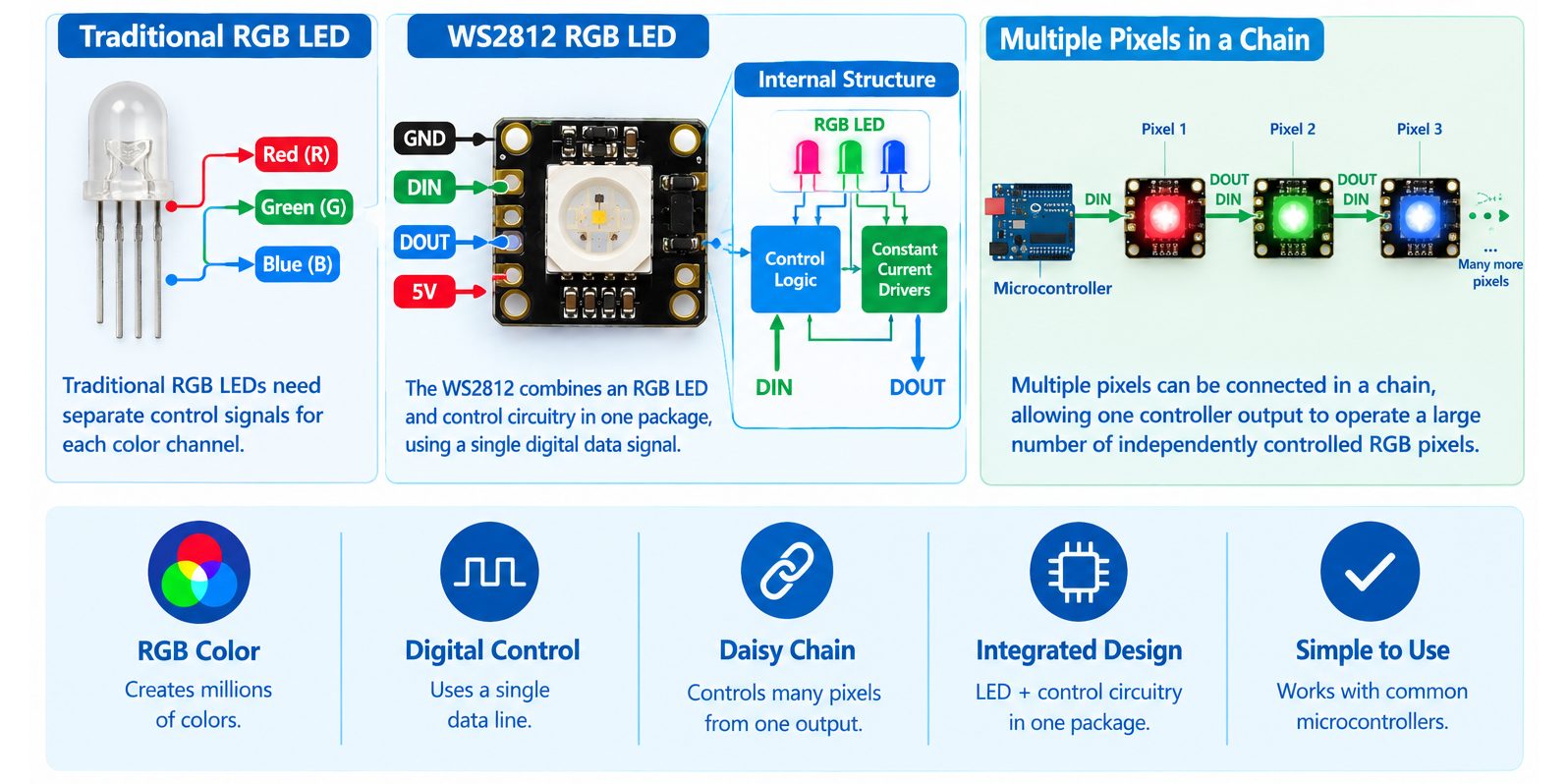
This is one of the main reasons the WS2812 family became widely used in programmable LED strips, rings, matrices, indicators, wearable electronics, robotics, decorative lighting, and interactive projects.
For hobbyists and beginners, the WS2812 is attractive because the wiring can be relatively simple. For engineers, the device is also interesting because the system involves important design considerations such as logic-level compatibility, signal timing, power distribution, voltage drop, current consumption, and data integrity.
In this article, we’ll explore everything you need to know about WS2812 LEDs, from basic concepts to advanced implementation, with practical examples you can build today using components available at Makers Electronics Store.
2- What Is the WS2812 RGB LED?
Integrated RGB LED and Controller
The WS2812 is not simply a conventional RGB LED.
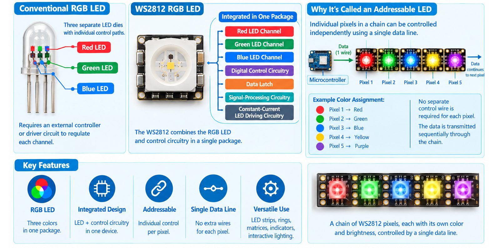
A conventional RGB LED normally contains three LED dies:
- Red
- Green
- Blue
Each color requires its own control path. An external controller or driver circuit must therefore regulate the current through each channel.
The WS2812 integrates the RGB LED and its control circuitry into a single package.
The integrated device contains:
- Red LED channel
- Green LED channel
- Blue LED channel
- Digital control circuitry
- Data latch
- Signal-processing circuitry
- Constant-current LED driving circuitry
The result is an individually controllable RGB pixel that can receive digital color information from a microcontroller.
Why Is the WS2812 Called an Addressable LED?
The term “addressable” means that individual pixels in a chain can be controlled independently.
For example, suppose five WS2812 pixels are connected together.
A microcontroller can send color information such as:
- Pixel 1 → Red
- Pixel 2 → Green
- Pixel 3 → Blue
- Pixel 4 → Yellow
- Pixel 5 → Purple
No separate control wire is required for each pixel.
The data is transmitted sequentially through the chain, and each pixel takes the portion of the data intended for it.
This is one of the main reasons the WS2812 became popular in LED strips, rings, matrices, indicators, and interactive lighting systems.
3- Internal Structure of the WS2812
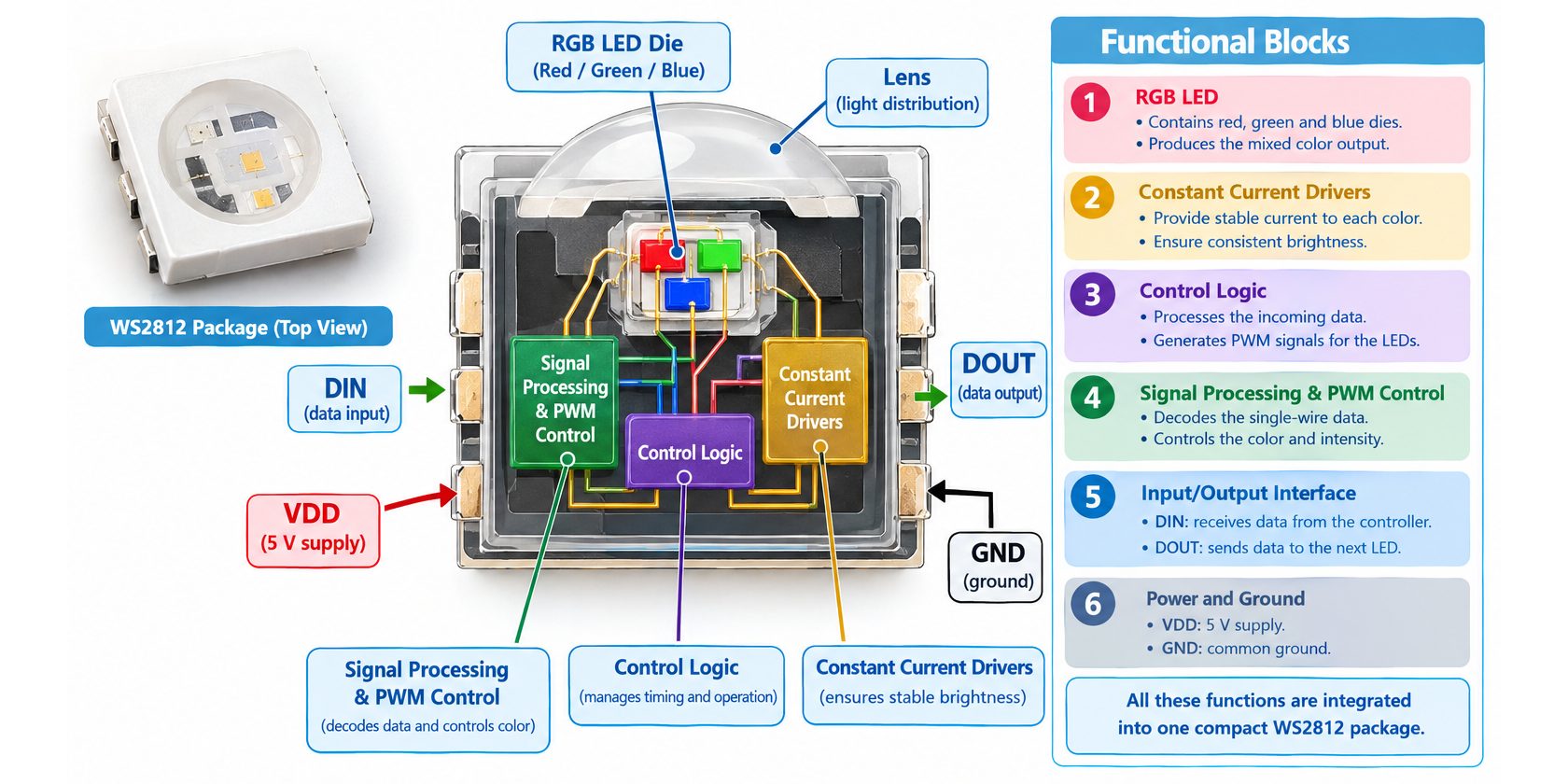
The WS2812 can be understood as several functional blocks integrated into one small package.
RGB LED Section
The optical section contains three LED channels:
- Red
- Green
- Blue
Each channel is independently controlled.
By changing the intensity of each channel, the device can generate a wide range of colors.
Digital Data Processing Section
- The internal control circuit receives the digital signal from the data input.
- It interprets the timing of the incoming signal and converts it into digital color information.
Data Latch
- The received color values are stored internally.
- This allows the LED to maintain the selected color while the next data sequence is transmitted.
Signal Reshaping and Data Output
- In a chain of LEDs, the data signal must travel from one pixel to the next.
- The internal circuitry helps regenerate the signal before passing it onward.
- This makes long chains possible without requiring a separate controller for every pixel.
Constant-Current LED Driving
- The internal driver controls the current delivered to the RGB channels.
- The exact current depends on the specific WS2812 family member and revision.
- For example, Worldsemi currently specifies 12 mA per RGB channel for the WS2812B-V6.
- This is an important reason not to automatically apply the commonly quoted “60 mA per pixel” figure to every WS2812 revision.
4- WS2812 Pins and Their Functions
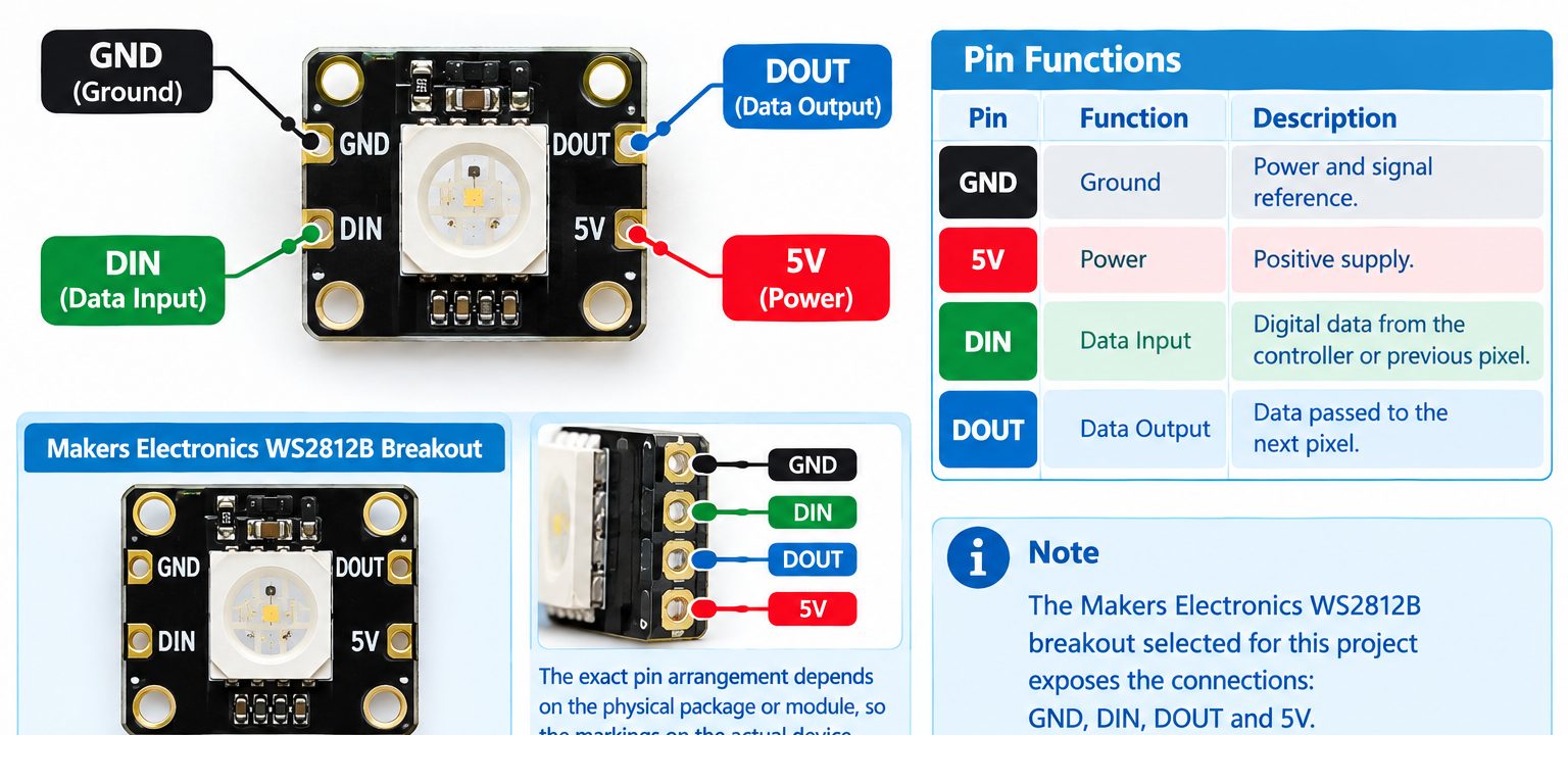
A common WS2812B breakout module exposes four connections:
| Pin | Function | Description |
|---|---|---|
| 5V | Power | Positive supply |
| GND | Ground | Power and signal reference |
| DIN | Data Input | Digital data from the controller or previous pixel |
| DOUT | Data Output | Data passed to the next pixel |
The exact pin arrangement depends on the physical package or module, so the markings on the actual device should always be checked.
For the Makers Electronics WS2812B breakout selected for this project, the exposed connections are GND, DIN, DOUT, and 5V.
DIN
- DIN is the data input.
- For the first pixel, it connects to the microcontroller’s selected digital output through the recommended series resistor.
- For a chain of pixels, DIN of a pixel normally receives the DOUT signal from the previous pixel.
DOUT
- DOUT is the data output.
- It is used when connecting another WS2812 pixel.
- For a single-pixel project, DOUT can remain unconnected.
5V
- This is the positive supply connection.
- For the practical project in this article, the WS2812B module is powered from a regulated 5 V supply.
GND
- Ground is the common electrical reference.
- The LED ground and Arduino ground must be connected together.
5- How Does the WS2812 RGB LED Work?
The WS2812 operates as a combination of:
- Digital data receiver
- Internal data latch
- Signal regeneration circuit
- RGB LED driver
- Red, green, and blue LED channels
The microcontroller sends a stream of digital information to the first WS2812.
The first pixel receives the data and extracts the portion intended for itself.
The remaining data is passed toward the next pixel.
This process continues through the chain.
The microcontroller therefore does not need separate control lines for every RGB LED.
Basic Operating Sequence
The overall operation can be simplified as: Microcontroller → Data Stream → WS2812 → LED Color Output
For a chain: Microcontroller → Pixel 1 → Pixel 2 → Pixel 3 → Pixel 4 → …
Each pixel receives the serial data, processes its own information, and forwards the remaining information.
6- How Does the WS2812 Produce Different Colors?
The WS2812 produces colors by controlling the relative intensity of its red, green, and blue LED channels.
Each channel is represented by an 8-bit value.
For example:
| Red | Green | Blue | Approximate Result |
|---|---|---|---|
| 255 | 0 | 0 | Red |
| 0 | 255 | 0 | Green |
| 0 | 0 | 255 | Blue |
| 255 | 255 | 0 | Yellow |
| 0 | 255 | 255 | Cyan |
| 255 | 0 | 255 | Magenta |
| 255 | 255 | 255 | White |
| 0 | 0 | 0 | Off |
The numbers represent intensity rather than separate ON/OFF commands.
For example: RGB = 255, 0, 0
means maximum red and no green or blue.
While: RGB = 128, 0, 128
produces a lower-intensity mixture of red and blue, resulting in a purple/magenta appearance.
Brightness Control
Brightness can also be controlled by reducing the RGB values.
For example:
- 255, 0, 0 produces maximum red.
- 50, 0, 0 produces a much dimmer red.
This is useful because reducing brightness also reduces power consumption.
7- The Various Package of the WS2812 RGB LED
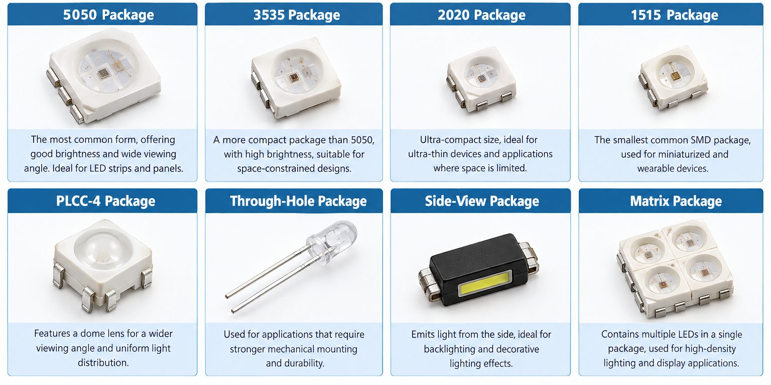
The WS2812 family is available in considerably more forms than the familiar 5050 LED used on many addressable LED strips.
The package and physical format can be selected according to the required size, brightness, viewing direction, PCB space, and mechanical construction.
1- 5050 Package
- The 5050 package is one of the most recognizable WS2812 formats.
- The name refers approximately to a package size of 5.0 mm × 5.0 mm.
- The larger package provides a practical balance between optical output, PCB space, and ease of handling.
- The WS2812B family includes 5050 versions, including the WS2812B-V6 and WS2812B-B-V6.
2- 3535 Package
- The 3535 package is smaller than the traditional 5050 package.
- It is useful when PCB space is limited while maintaining the functionality of an individually controlled RGB pixel.
- Worldsemi lists 3535 packages among the WS2812B-V6 options.
3- 2020 Package
- The 2020 package is designed for compact and high-density applications.
- Worldsemi currently lists the WS2812B-2020-V6 as a 4-pin, 8-bit RGBIC device.
4- 4020 Side-View Package
- The WS2812B-4020-V6 uses a side-view package.
- Instead of being optimized for conventional top-emitting PCB layouts, a side-view package can be useful when light needs to be directed from the edge of a PCB or into a mechanical structure.
- Worldsemi lists the WS2812B-4020-V6 as a 4020 side-view device.
5- 1313 and Miniature Packages
- Worldsemi also lists very small WS2812-family packages, including 1313 and 0909 variants.
- These packages are intended for applications where PCB area and pixel density are important.
- However, miniature packages generally require more careful PCB assembly and manufacturing processes than larger 5050 devices.
6- Through-Hole WS2812 Devices
The WS2812 family is not limited to surface-mount packages.
Worldsemi lists WS2812D-V6 devices in:
- 5 mm flat packages
- 5 mm straw-hat packages
- 8 mm straw-hat packages
These formats can be useful for prototypes, indicators, decorative lighting, and applications where through-hole assembly is preferred.
7- Modules, Strips, Rings, and Matrices
The same basic WS2812 technology can be incorporated into different physical products.
Common formats include:
- Individual LEDs
- Breakout modules
- LED strips
- LED rings
- LED matrices
- Custom PCBs
- Decorative LED assemblies
This means the engineer can choose the physical implementation without fundamentally changing the method used to send pixel data.
8- Different Types of WS2812 RGB LEDs
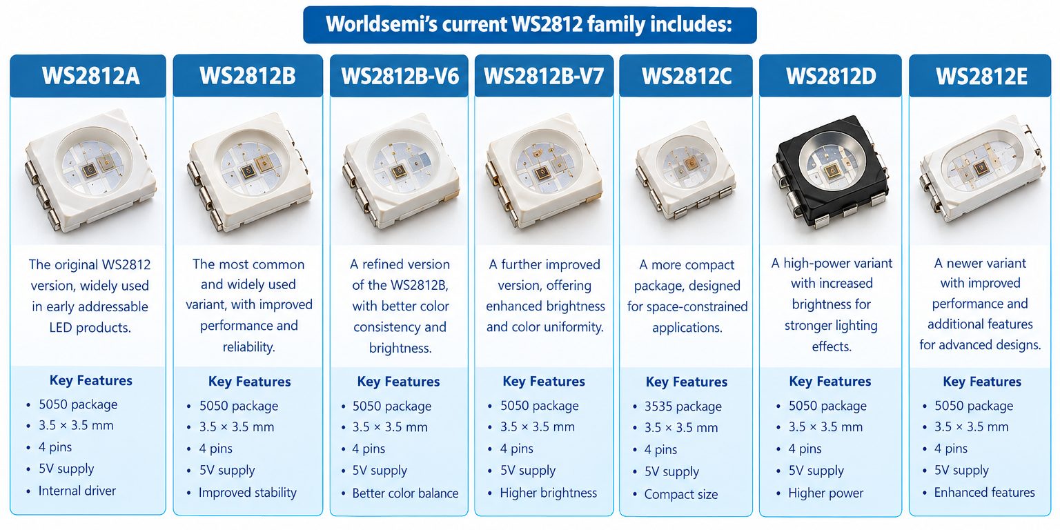
The WS2812 family contains several different devices and revisions.
It is important to understand that the name “WS2812” does not identify one completely fixed electrical specification.
Worldsemi’s current WS2812 family table identifies:
- WS2812A
- WS2812B
- WS2812B-V6
- WS2812B-V7
- WS2812C
- WS2812D
- WS2812E
The same family table shows important differences in operating voltage, RGB current, package format, internal capacitor, reverse-connection protection, and overvoltage protection.
Worldsemi also currently lists specific revisions such as WS2812B-V6 and WS2812B-2020-V6.
WS2812A
The WS2812A is an 8-bit, 256-level RGB addressable LED family member.
In Worldsemi’s family selection table, WS2812A is listed with:
- 3.3–5.5 V supply
- 16 mA × 3 RGB current
- 5050 package
- Internal capacitor
- Reverse-connection protection
- Overvoltage protection
- No dual-signal input
However, Worldsemi’s current homepage separately promotes a newer WS2812A product specification showing a 4.0–5.3 V range, 32 mA, a 5054 package, and approximately four times the brightness of WS2812B-V6.
This difference is important.
It demonstrates why engineers should use the exact product page or datasheet for the exact ordering code instead of assuming that every device carrying the name “WS2812A” has one universal specification.
WS2812B
WS2812B is one of the most widely encountered members of the family.
The current Worldsemi family table lists:
- 3.3–5.5 V
- 8-bit / 256-level grayscale
- 12 mA × 3 RGB current
- 5050, 3535, 2427, 2020, 1313, and 4020 package options
- Internal capacitor
- Reverse-connection protection
- Overvoltage protection
- No dual-signal architecture
Because WS2812B is available in several package sizes, it is suitable for both general-purpose projects and compact PCB designs.
WS2812B-V6
WS2812B-V6 is a particularly important revision.
Worldsemi specifies:
- 3.3–5.5 V
- 8-bit / 256-level control
- 12 mA × 3 RGB current
- Multiple package options
Worldsemi’s September 2025 upgrade notice states that the V6 upgrade retained the communication protocol and package size while improving several internal parameters. The company specifically states that the upgrade reduced quiescent power consumption, improved power-on behavior, enabled 3.3 V constant-current operation, allowed DIN/DOUT interchangeability, and adjusted the control signal threshold so that a 3.3 V signal can control a 5 V-powered device.
WS2812B-V7
WS2812B-V7 should be treated as a distinct newer revision rather than simply being described as an ordinary WS2812B.
Worldsemi currently describes the WS2812B-V7 as:
- 3.3–5.5 V
- 12 mA
- Approximately twice the brightness of WS2812B-V6
Worldsemi’s September 2025 product announcement also states that the V7 can provide more than twice the brightness of V6, while the current homepage presents it as a two-times-brightness version.
Therefore, when selecting WS2812B-V7 for a project, the exact V7 documentation should be checked rather than treating it as electrically identical to V6.
WS2812C
WS2812C is the lower-current member of the WS2812 family.
Worldsemi lists:
- 3.3–5.5 V
- 8-bit / 256-level grayscale
- 5 mA × 3 RGB current
- 5050, 3535, 2427, 2020, 1313, and 4020 packages
- No internal capacitor listed
- No reverse-connection protection listed
- No overvoltage protection listed
- No dual-signal architecture
The lower channel current can be useful when power consumption is an important design consideration.
However, the reduced protection features mean that the external circuit should be designed with appropriate care.
WS2812D
WS2812D is particularly different in physical format.
Worldsemi lists:
- 3.3–5.5 V
- 8-bit / 256-level grayscale
- 12 mA × 3 RGB current
- Φ5 flat package
- Φ5 straw-hat package
- Φ8 straw-hat package
- Reverse-connection protection
- Overvoltage protection
These through-hole-style formats can be useful for prototypes, indicators, decorative lighting, and projects where a traditional through-hole LED shape is preferred.
WS2812E
WS2812E is another member with different electrical characteristics.
Worldsemi lists:
- 3.8–5.5 V
- 8-bit / 256-level grayscale
- 12 mA × 3 RGB current
- 5050, 3535, 2427, 2020, 1313, and 4020 packages
- Internal capacitor
- Reverse-connection protection
- Overvoltage protection
The important point is that its minimum supply voltage is higher than the 3.3 V minimum listed for several other WS2812 family members.
The Main Differences
The most important differences are not simply the package names.
They include:
- Operating voltage :Most of these versions support a 3.3–5.5 V range, while WS2812E is listed at 3.8–5.5 V.
- RGB channel current :WS2812C is listed at only 5 mA × 3, while WS2812B, WS2812D, and WS2812E are listed at 12 mA × 3.
- Physical package :WS2812B and WS2812E are available in several surface-mount packages, while WS2812D is designed around through-hole LED-style packages.
- Protection :WS2812C does not have the same listed protection features as several other members of the family.
- Revision :WS2812B-V6 and WS2812B-V7 should not be treated as identical products. Worldsemi specifically documents electrical and performance changes between revisions.
9- WS2812 Communication Protocol
One of the most important characteristics of the WS2812 is its single-wire digital communication method.
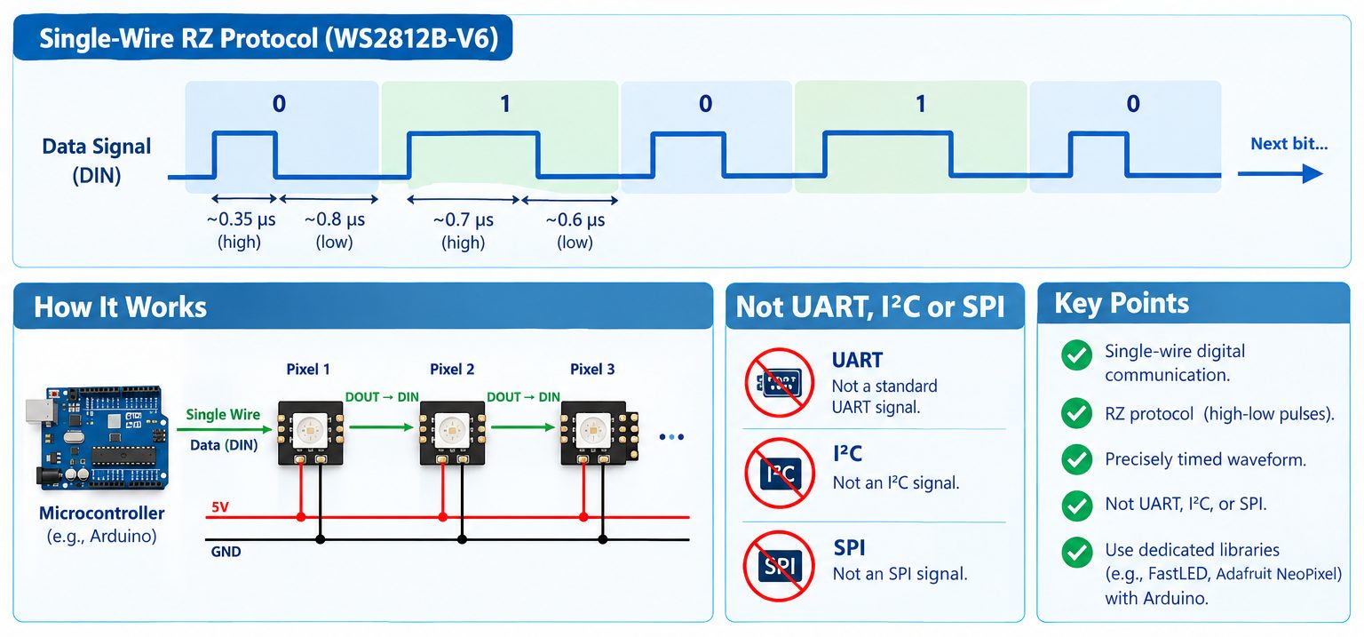
Worldsemi identifies the WS2812B-V6 communication system as a single-wire RZ protocol.
The data signal is not ordinary UART, I²C, or SPI.
Instead, the controller must generate a precisely timed digital waveform.
This is why dedicated libraries are normally used when controlling WS2812 LEDs with Arduino.
Why Timing Matters
- The WS2812 determines whether a transmitted bit represents a particular logical value based on the timing characteristics of the waveform.
- Therefore, a program that simply sends arbitrary HIGH and LOW states will not reliably control the LED.
- The microcontroller must generate the correct timing.
- This is one reason libraries such as Adafruit NeoPixel are useful: they handle the low-level signaling so the programmer can concentrate on the desired colors and animation.
24-Bit Color Data
A conventional WS2812 RGB pixel uses 8 bits for each color channel:
- 8 bits red
- 8 bits green
- 8 bits blue
Therefore: 8 + 8 + 8 = 24 bits per RGB pixel
Each color channel has 256 possible digital levels.
The theoretical number of RGB combinations is: 256 × 256 × 256 = 16,777,216 colors
The actual visual result depends on LED characteristics, current, optical conditions, brightness settings, and the implementation.
10- Power Supply Requirements
Power is one of the most important considerations when working with addressable RGB LEDs.
A circuit can have completely correct software and wiring but still behave incorrectly if the power supply cannot provide the required current or if voltage drops occur along the wiring.
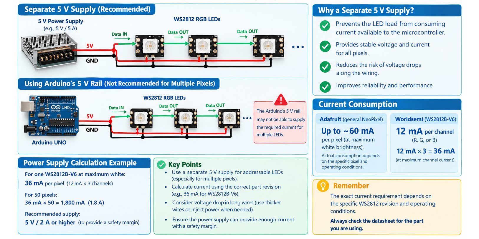
Why the WS2812 Needs a Separate Supply
For a single low-power pixel, powering the LED from an Arduino 5 V rail may sometimes be possible.
However, using a separate 5 V supply is a better engineering approach when working with addressable LEDs because it prevents the LED load from unnecessarily consuming current available to the microcontroller.
Adafruit notes that individual NeoPixels can draw up to approximately 60 mA in some implementations at maximum white brightness, although actual consumption depends on the specific pixel and operating conditions.
For the WS2812B-V6 specifically, Worldsemi specifies 12 mA per RGB channel, which gives approximately: 12 mA × 3 = 36 mA
for the RGB channels at their specified maximum channel current.
Therefore, the exact part revision should be used when calculating power requirements rather than blindly applying a generic 60 mA figure.
Power Calculation
For N pixels, a conservative engineering estimate can be written as: Total LED current ≈ N × maximum current per pixel
For the WS2812B-V6: Maximum RGB channel current ≈ 36 mA per pixel
Therefore, for 10 pixels: 10 × 36 mA = 360 mA
For 50 pixels: 50 × 36 mA = 1.8 A
These calculations represent the RGB channel current based on the Worldsemi V6 specification and should not be confused with a universal specification for every WS2812-compatible product.
Voltage Drop
When many LEDs are connected in a long strip, resistance in the copper traces and wires causes voltage drop.
The voltage near the beginning of a strip may therefore be higher than the voltage near the far end.
This can produce:
- Reduced brightness
- Incorrect colors
- Flickering
- Unstable operation
Larger installations may require power injection at multiple points.
11- Data-Line Resistor and Power-Supply Capacitor
Two simple passive components can significantly improve the reliability of a WS2812 circuit.
470 Ω Data Resistor
The resistor is connected between the microcontroller output and the DIN input.
Its main purpose is to help reduce signal ringing and reflections on the data line.
For the practical circuit: Arduino D6 → 470 Ω → DIN
Adafruit recommends approximately 300–500 Ω for this purpose and recommends placing the resistor close to the first pixel.
1000 µF Power Capacitor
A large electrolytic capacitor is placed across the LED supply.
The selected component is: 1000 µF / 10 V
Its purpose is to provide local energy storage and help absorb sudden changes in current demand.
Adafruit recommends a 500–1000 µF capacitor for many NeoPixel installations, especially when connecting to larger power sources.
Capacitor Polarity
The capacitor is polarized.
Therefore:
- Positive capacitor lead → +5 V
- Negative capacitor lead → GND
Never reverse these connections.
Keep the Data Wire Short
The data signal should travel through the shortest practical connection between the Arduino and the first WS2812.
Long wires can increase signal-integrity problems.
For larger installations, additional signal-conditioning or level-shifting techniques may be required depending on the controller, cable length, pixel revision, and environment.
12- WS2812 RGB LED Circuit and Detailed Wiring
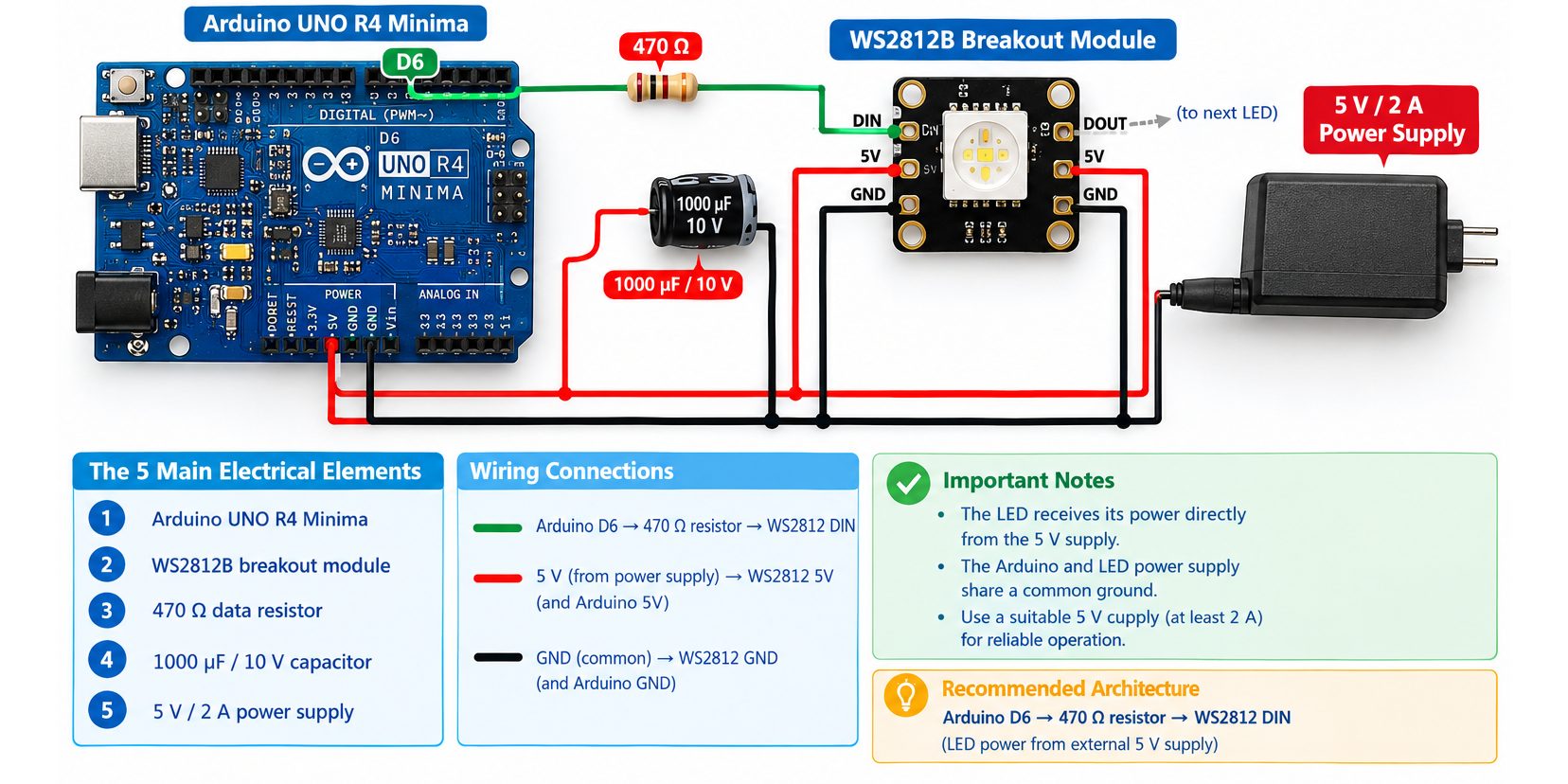
The practical circuit consists of five main electrical elements:
- Arduino UNO R4 Minima
- WS2812B breakout module
- 470 Ω data resistor
- 1000 µF / 10 V capacitor
- 5 V / 2 A power supply
The recommended architecture is: Arduino D6 → 470 Ω resistor → WS2812 DIN
The LED receives its power directly from the external 5 V supply.
The Arduino and LED power supply share a common ground.
Power Connections
Connect:
- 5 V power supply positive → WS2812 5V
- 5 V power supply negative → WS2812 GND
- 5 V power supply negative → Arduino GND
This common ground is essential because the Arduino’s data signal must be referenced to the same electrical ground as the WS2812.
Data Connection
Connect: Arduino D6 → 470 Ω resistor → WS2812 DIN
The resistor should be physically located close to the WS2812 data input where practical.
Capacitor Connection
Connect the 1000 µF capacitor directly across the WS2812 power input:
- Capacitor positive (+) → 5 V
- Capacitor negative (−) → GND
Because the capacitor is polarized, reversing it can damage the capacitor.
DOUT Connection
Because this example uses only one pixel: WS2812 DOUT → No connection
If additional pixels are added: Pixel 1 DOUT → Pixel 2 DIN
Simplified Circuit Schematic
                  +----------------------+
                  |  5 V / 2 A Supply    |
                  |                      |
                  |   +5V          GND   |
                  +----|------------|----+
                       |            |
                       |            +------------------+
                       |                               |
                       |                               |
                 +-----+-----+                    +----+----+
                 |           |                    | Arduino |
                 | WS2812B   |                    | UNO R4   |
                 | Breakout  |                    | Minima   |
                 |           |                    |          |
                 | 5V   GND  |                    | GND      |
                 | |     |   |                    | D6       |
                 | |     |   |                    +--+---+---+
                 +-|-----|---+                       |
                   |     |                           |
                   |     +---------------------------+
                   |
                   |
             +-----+-----+
             | 1000 µF   |
             | 10 V      |
             | Capacitor  |
             +-----------+
               +       -
               |       |
               |       |
              5V      GND


Arduino D6
    |
    |
  470 Ω
 resistor
    |
    |
    +------------------> WS2812 DIN

WS2812 DOUT
    |
    +---- No connection for one pixel
- The most important point in this circuit is that the LED power path and the data path are separate.
- The Arduino D6 pin provides the control signal.
- The external 5 V supply provides the LED power.
- The Arduino ground and external power-supply ground are connected together.
13- Cascading Multiple WS2812 LEDs
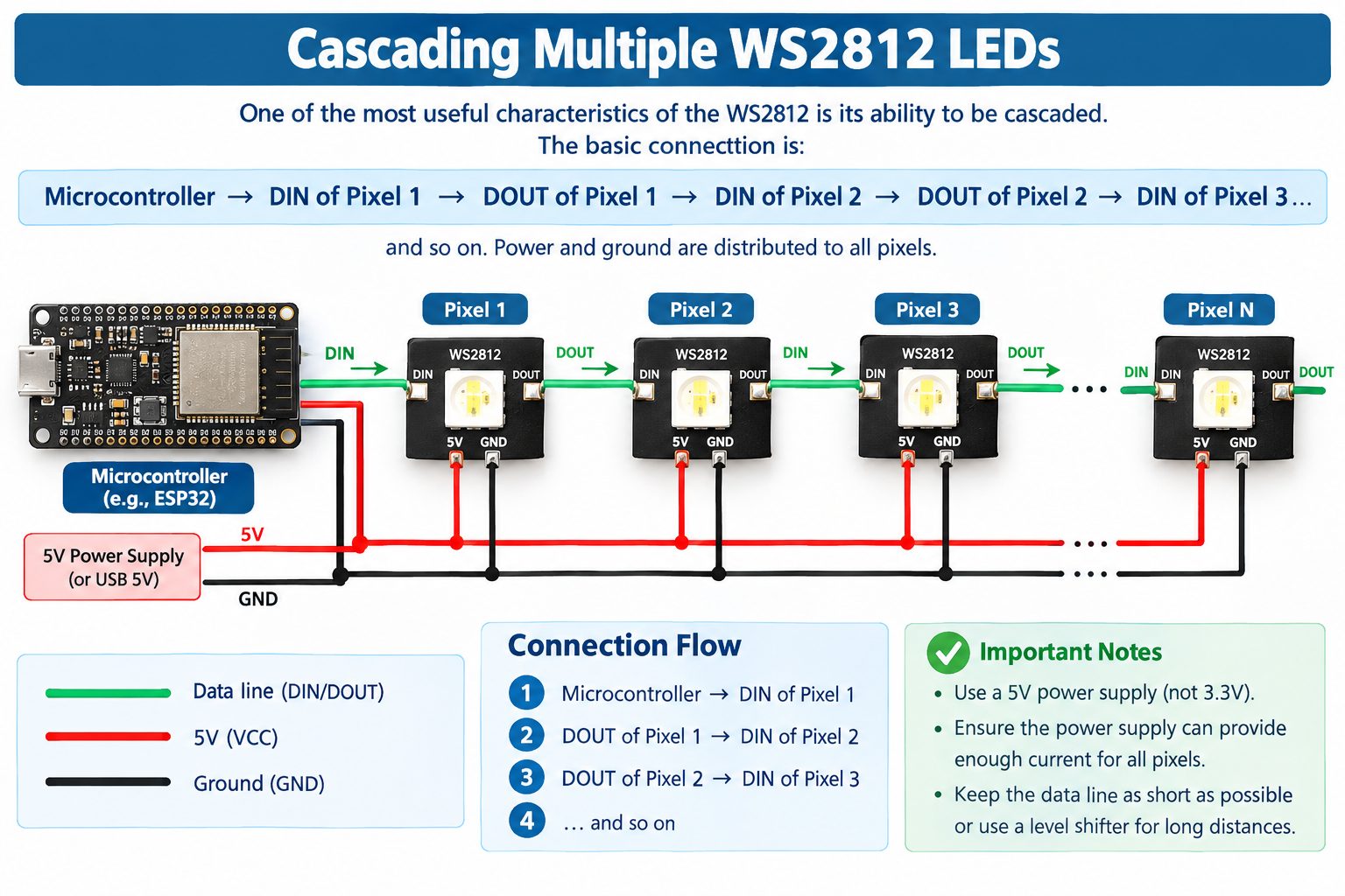
One of the most useful characteristics of the WS2812 is its ability to be cascaded.
The basic connection is:
- Microcontroller → DIN of Pixel 1
- DOUT of Pixel 1 → DIN of Pixel 2
- DOUT of Pixel 2 → DIN of Pixel 3
and so on.
Power and ground are distributed to all pixels.
How Data Moves Through the Chain
Suppose three pixels are connected.
The controller sends data for:
- Pixel 1
- Pixel 2
- Pixel 3
Pixel 1 consumes its portion and passes the remaining data to Pixel 2.
Pixel 2 does the same.
Pixel 3 receives its corresponding data and completes the chain.
This sequential architecture is why one microcontroller pin can control a large number of RGB pixels.
Data Direction Is Important
The physical direction of the data chain matters.
Always identify: DIN / DI / Data In
and DOUT / DO / Data Out
Do not assume the physical orientation of the LED automatically indicates the data direction.
For LED strips, arrows are commonly provided to indicate data direction.
Adafruit specifically recommends checking the actual labels and arrows on the product rather than blindly following a wiring diagram from a different strip or revision.
14- WS2812 RGB LED Applications
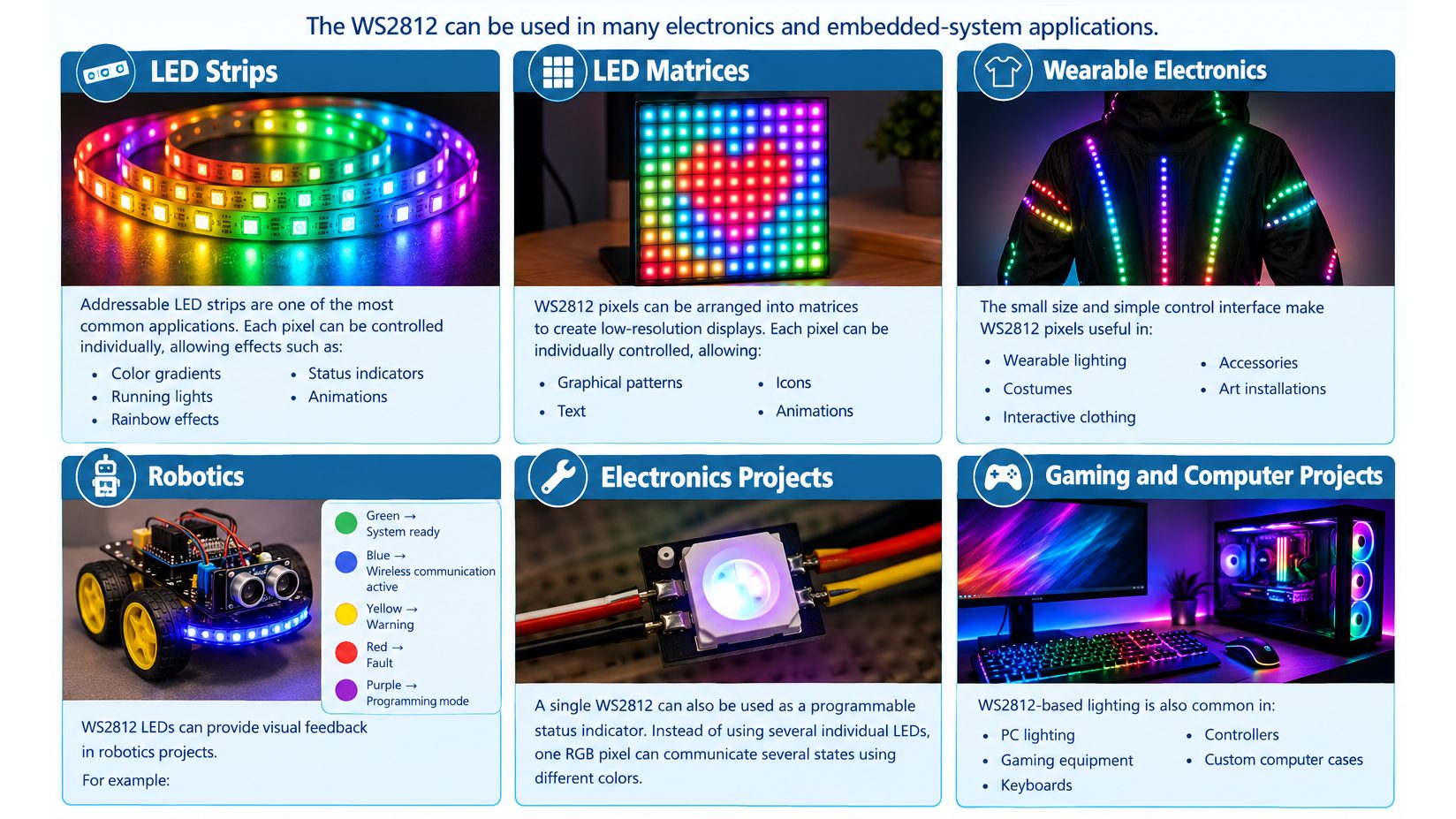
The WS2812 can be used in many electronics and embedded-system applications.
LED Strips
Addressable LED strips are one of the most common applications.
Each pixel can be controlled individually, allowing effects such as:
- Color gradients
- Running lights
- Rainbow effects
- Status indicators
- Animations
LED Matrices
WS2812 pixels can be arranged into matrices to create low-resolution displays.
Each pixel can be individually controlled, allowing graphical patterns, text, icons, and animations.
Wearable Electronics
The small size and simple control interface make WS2812 pixels useful in:
- Wearable lighting
- Costumes
- Interactive clothing
- Accessories
- Art installations
Robotics
WS2812 LEDs can provide visual feedback in robotics projects.
For example:
- Green → System ready
- Blue → Wireless communication active
- Yellow → Warning
- Red → Fault
- Purple → Programming mode
Electronics Projects
A single WS2812 can also be used as a programmable status indicator.
Instead of using several individual LEDs, one RGB pixel can communicate several states using different colors.
Gaming and Computer Projects
WS2812-based lighting is also common in:
- PC lighting
- Gaming equipment
- Keyboards
- Controllers
- Custom computer cases
15- Advantages and Limitations of the WS2812
Advantages
The WS2812 provides several important advantages.
- Simple Wiring: A single data line can control multiple pixels.
- Individual Pixel Control: Each pixel can display a different color.
- Integrated Controller: The LED and controller are integrated into the same package.
- Large Software Ecosystem: Arduino and other microcontroller platforms have extensive support for WS2812-compatible LEDs.
- Many Physical Formats: The technology is available in multiple package sizes and product formats.
- Scalable: A project can start with one pixel and later expand to a larger chain.
Limitations
The WS2812 also has limitations.
- Power Consumption Increases With Pixel Count: More pixels require more power.
- Power Distribution Becomes Important: Long strips can experience voltage drop.
- Timing Is Important: The data signal must follow the required timing protocol.
- Data Chain Dependency: A problem in a pixel or data connection can affect downstream pixels.
- Long Data Wires Can Cause Signal Problems: The signal becomes more difficult to maintain over long connections.
- Exact Specifications Depend on the Revision: Different WS2812-family products can have different electrical characteristics.
16- How Should You Choose the Right RGB LED?
Selecting the right addressable RGB LED depends on the requirements of the project rather than simply choosing the most popular part number.
Choose WS2812B for General-Purpose Projects
The WS2812B is a strong choice when the project requires:
- Individually addressable RGB pixels
- Simple wiring
- Arduino compatibility
- LED strips or modules
- Compact RGB lighting
- A large ecosystem of software libraries
For a beginner project, a WS2812B breakout module is particularly convenient because the LED is already mounted on a PCB.
Choose a Smaller Package When Space Is Limited
For compact PCB designs, smaller packages such as:
- 2020
- 1313
- 0909
- 3535
can be more appropriate.
However, PCB assembly becomes more demanding as the package size decreases.
Choose a Side-View Package When Optical Direction Matters
A side-view package such as the WS2812B-4020-V6 can be useful when the LED must illuminate sideways.
This is particularly relevant to edge indicators and specialized mechanical designs.
Consider WS2813 for Greater Chain Resilience
If a long LED chain is being designed and data-path resilience is especially important, the WS2813 family can be considered because of its dual-signal architecture.
Consider WS2811 When External LEDs Are Required
If the project requires an external RGB LED arrangement rather than an integrated RGB pixel, a WS2811-type driver can be more appropriate.
Always Check the Exact Revision
This is one of the most important engineering rules when selecting a WS2812-compatible component.
Do not assume that every product advertised simply as “WS2812B” has identical:
- Supply voltage
- Current consumption
- Logic thresholds
- Internal protection
- Data behavior
The exact manufacturer and revision should be identified.
17- Comparisons between WS2812 vs WS2813 vs WS2815 vs WS2816
WS2812, WS2813, WS2815, and WS2816 should not be considered merely different names for the same LED.
Worldsemi currently categorizes them as separate digital LED families with different power and signaling architectures.
| Parameter | WS2812 | WS2813 | WS2815 | WS2816 |
|---|---|---|---|---|
| Supply family | DC5V | DC5V | DC12V | DC5V |
| Signal architecture | Single-signal | Dual-signal | Dual-signal | Dual-signal |
| Typical grayscale | 8-bit / 256 | 8-bit / 256 | 8-bit / 256 | 16-bit / 65,536 for B/C |
| RGB current | Depends on version | Depends on version | Depends on version | Depends on version |
| Main design characteristic | Simple 5 V addressable RGB | Dual-signal architecture | 12 V dual-signal architecture | Higher grayscale dual-signal architecture |
| Typical packages | 5050 and smaller | 5050, 3535, 2121, 1313 | 5050, 3535, 2121, 1313 | 5050, 3535, 2427, 2121, 2020, 1313 |
The Simplified Difference
A useful way to remember the four families is:
- WS2812 → 5 V + single-signal + 8-bit RGB
- WS2813 → 5 V + dual-signal + 8-bit RGB
- WS2815 → 12 V + dual-signal + 8-bit RGB
- WS2816 → 5 V + dual-signal + higher grayscale resolution
These descriptions are simplified family-level summaries. The exact electrical specifications still depend on the particular model and revision.
18. Communication and Controlling the WS2812 with Arduino
The WS2812 can be controlled directly by an Arduino through its digital data input. The Arduino sends the LED color information as a timed digital signal through a single data line.
For a practical setup, the Arduino UNO can use digital pin D6 as the data output. A 470 Ω resistor can be placed between the Arduino data pin and the WS2812 DIN pin to help protect the data line from signal reflections and transients.
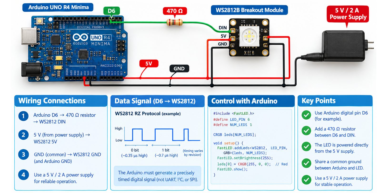
The basic connection is:
Arduino UNO                     WS2812
-----------                     ------
D6 ───── 470 Ω ───────────────► DIN
GND ──────────────────────────► GND
5 V Supply ───────────────────► 5V
The WS2812 and Arduino must share a common ground. The LED should preferably be powered from an appropriate external 5 V supply rather than relying on the Arduino board’s 5 V pin when the project contains several LEDs.
Controlling the WS2812 with Arduino
The Arduino can control the WS2812 using a suitable library, such as the Adafruit NeoPixel library. The library handles the precise timing required by the WS2812 communication protocol.
For a single WS2812 RGB LED, the Arduino can send three 8-bit color values:
- Red: 0–255
- Green: 0–255
- Blue: 0–255
For example, the following program turns the LED red:
#include <Adafruit_NeoPixel.h>

#define LED_PIN 6
#define NUM_LEDS 1

Adafruit_NeoPixel strip(NUM_LEDS, LED_PIN, NEO_GRB + NEO_KHZ800);

void setup() {
  strip.begin();
  strip.setBrightness(100);

  strip.setPixelColor(0, strip.Color(255, 0, 0));
  strip.show();
}

void loop() {
}
In this example, LED_PIN defines the Arduino output pin connected to the WS2812 DIN pin, while NUM_LEDS specifies the number of LEDs in the chain.
The setPixelColor() function assigns the RGB value to the LED. In this case:
Red   = 255
Green = 0
Blue  = 0
The show() function then transmits the prepared data to the WS2812.
Creating Different Colors
Changing the RGB values allows the Arduino to produce different colors.
For example:
strip.setPixelColor(0, strip.Color(0, 255, 0));   // Green
strip.show();
or:
strip.setPixelColor(0, strip.Color(0, 0, 255));   // Blue
strip.show();
The Arduino can also create mixed colors by combining the three channels:
strip.setPixelColor(0, strip.Color(255, 255, 0)); // Yellow
strip.show();
This approach can be extended to create fading effects, blinking patterns, color transitions, and other lighting effects.
Controlling Multiple WS2812 LEDs
The Arduino can control multiple WS2812 LEDs connected in a cascade. The first LED receives data from the Arduino, while its DOUT connection passes the remaining data to the next LED.
Arduino D6
    │
    ▼
  DIN ┌────────┐ DOUT ───► DIN ┌────────┐ DOUT ───► ...
      │ WS2812 │               │ WS2812 │
      └────────┘               └────────┘
       LED 1                    LED 2
Each LED can receive its own RGB value, allowing the Arduino to control an entire strip or matrix using one digital output.
19. Communication and Controlling the WS2812 with ESP32
The ESP32 can also communicate directly with WS2812 LEDs through a digital GPIO pin. The communication principle is similar to Arduino, but the ESP32 uses 3.3 V logic.
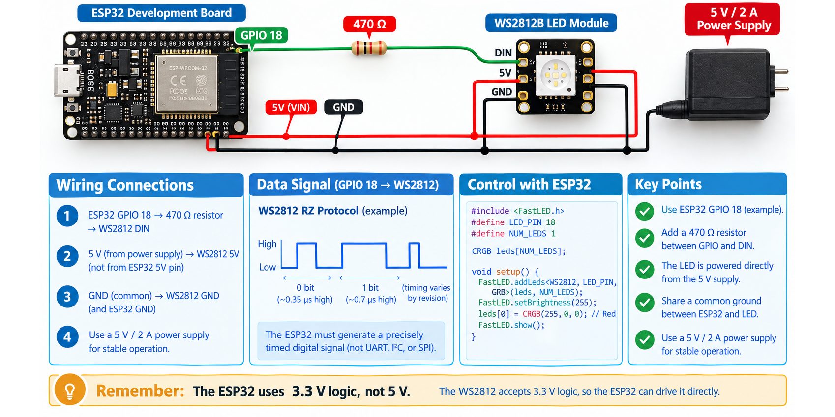
A typical connection can use GPIO 5:
ESP32                          WS2812
-----                          ------
GPIO 5 ──────────────────────► DIN
GND ─────────────────────────► GND
5 V Supply ──────────────────► 5V
The ESP32 and WS2812 must share a common ground so that the data signal has the correct reference.
Because the ESP32 GPIO operates at 3.3 V while many WS2812 installations are powered from 5 V, logic-level compatibility should be considered. Depending on the particular WS2812 revision, wiring length, supply voltage, and signal conditions, a 3.3 V-to-5 V logic-level shifter can provide a more robust data signal.
Controlling the WS2812 with ESP32
The ESP32 can use the same Adafruit NeoPixel library to simplify WS2812 control.
For example, the following program turns a single WS2812 blue:
#include <Adafruit_NeoPixel.h>

#define LED_PIN 5
#define NUM_LEDS 1

Adafruit_NeoPixel strip(NUM_LEDS, LED_PIN, NEO_GRB + NEO_KHZ800);

void setup() {
  strip.begin();
  strip.setBrightness(100);

  strip.setPixelColor(0, strip.Color(0, 0, 255));
  strip.show();
}

void loop() {
}
Here, the ESP32 sends:
Red   = 0
Green = 0
Blue  = 255
Therefore, the WS2812 produces blue light.
Controlling Colors and Brightness
The ESP32 can modify the RGB values in exactly the same general way as the Arduino.
For example:
strip.setPixelColor(0, strip.Color(255, 0, 0));
strip.show();
produces red, while:
strip.setPixelColor(0, strip.Color(255, 255, 255));
strip.show();
sets all three channels to their maximum value, producing white.
Brightness can also be adjusted:
strip.setBrightness(50);The brightness setting changes the effective intensity of the LED output while the RGB color values determine the color itself.
Controlling Multiple WS2812 LEDs with ESP32
The ESP32 can control a complete chain of WS2812 LEDs from one GPIO.
For example, five LEDs can be assigned different colors:
strip.setPixelColor(0, strip.Color(255, 0, 0));
strip.setPixelColor(1, strip.Color(0, 255, 0));
strip.setPixelColor(2, strip.Color(0, 0, 255));
strip.setPixelColor(3, strip.Color(255, 255, 0));
strip.setPixelColor(4, strip.Color(255, 255, 255));

strip.show();
The ESP32 sends the complete sequence through the first LED. Each WS2812 processes the portion of the data intended for it and passes the remaining data through its DOUT pin.
20- How Should You Choose the Right Projects Controller?
The ESP32 becomes particularly useful when the WS2812 project requires functionality beyond basic LED control. Because the ESP32 provides substantially more processing capability and built-in wireless connectivity than a basic Arduino UNO, it can be used for projects where the LED lighting is controlled by additional software functions.
For example, an ESP32-based WS2812 project can combine the LEDs with:
- Wi-Fi control
- Bluetooth control
- Web-based interfaces
- Sensors
- Buttons and switches
- Dynamic lighting effects
- Larger LED installations
Therefore, Arduino and ESP32 can both control WS2812 LEDs, but the appropriate controller depends on the requirements of the project. The WS2812 communication principle remains based on sending the required digital data stream to the LED’s DIN input, while the microcontroller determines what colors, brightness levels, and lighting patterns are transmitted.
21- Common WS2812 Problems and Troubleshooting
The LED Does Not Light
Check:
- 5 V is reaching the LED.
- GND is connected.
- Arduino GND and LED GND are common.
- Data is connected to DIN.
- The correct Arduino pin is defined in the program.
- The LED count is correct.
- The library is installed correctly.
The LED Is the Wrong Color
Check the color-order setting.
Try verifying whether the device requires: GRB
rather than: RGB
Many WS2812-compatible implementations use GRB ordering.
The LED Flickers
Possible causes include:
- Poor power connection
- Voltage drop
- Long data wire
- Electrical noise
- Incorrect data timing
- Insufficient power supply
- Missing or incorrectly placed data resistor
Check the 5 V supply voltage directly at the LED.
The First LED Works but the Others Do Not
Check: Pixel 1 DOUT → Pixel 2 DIN
- Then check the power and ground connections for the downstream pixels.
- Also verify the physical direction of the data chain.
The LED Works With One Pixel but Fails With Many
This commonly points toward a power-distribution or signal-integrity problem.
Check:
- Power-supply current capacity
- Voltage drop
- Power injection
- Ground wiring
- Data-wire length
- Data direction
- Signal level
The Arduino Resets When the LEDs Change Color
- This can happen when the LED load causes a significant supply disturbance.
- Use an appropriately sized external supply for the LEDs and ensure the power system is properly distributed.
- A bulk capacitor across the LED supply can also help reduce abrupt supply disturbances.
The LED Works Randomly
Intermittent operation can result from:
- Loose wiring
- Poor ground connection
- Incorrect DIN/DOUT direction
- Excessively long data wire
- Electrical noise
- Inadequate power
- Incorrect timing configuration
Troubleshoot the circuit one pixel at a time before expanding it.
22- Frequently Asked Questions
Is the WS2812 an RGB LED?
Yes: The WS2812 is an addressable RGB LED device with integrated digital control circuitry.
What voltage does the WS2812B-V6 use?
- Worldsemi specifies the WS2812B-V6 for a supply range of 3.3 V to 5.5 V.
- For the practical project in this article, a regulated 5 V supply is used.
How many colors can a WS2812 display?
With 8-bit control for each of the three RGB channels, there are theoretically: 256 × 256 × 256 = 16,777,216 RGB combinations.
Can one Arduino pin control multiple WS2812 LEDs?
Yes: Multiple pixels can be connected in a serial chain, allowing one data output to control many individually addressable pixels.
Does every WS2812 use the same current?
No.
- The exact current depends on the specific device and revision.
- For example, Worldsemi specifies 12 mA per RGB channel for the WS2812B-V6.
- Therefore, the exact part number should be checked before calculating power requirements.
Does the WS2812 require a resistor?
- A series resistor on the data line to the first pixel is strongly recommended for reliable operation.
- A value around 300–500 Ω is commonly recommended, and this project uses 470 Ω.
Why is a capacitor used with the WS2812?
- A bulk capacitor across the LED supply helps provide local energy storage and reduces the effects of sudden changes in current demand.
- This project uses a 1000 µF / 10 V capacitor.
Can the WS2812 be controlled directly from Arduino?
Yes: A suitable Arduino library can generate the required WS2812 data signal.
Why does my WS2812 show the wrong colors?
- The most common reason is an incorrect color-order configuration.
- Many WS2812 implementations use GRB rather than RGB byte ordering.
Can I connect WS2812 LEDs in series?
- The data path is cascaded from one pixel’s DOUT to the next pixel’s DIN.
- However, the power system should be treated as a distributed supply rather than simply relying on current flowing through the first pixel and onward through the entire chain.
Can I use a 3.3 V microcontroller with a 5 V WS2812?
- This depends on the exact WS2812 revision.
- The current WS2812B-V6 specifically supports a 3.3 V control signal when powered from 5 V according to Worldsemi.
- For other WS2812 products or older revisions, a suitable logic-level shifter may still be required for reliable operation.
Is WS2813 better than WS2812B?
- Not necessarily for every application.
- WS2813’s major advantage is its dual-signal architecture and improved chain resilience.
- For a simple project, WS2812B may be simpler and more economical.
23- Conclusion
The WS2812 RGB LED is one of the most useful addressable LED technologies for electronics and embedded-system projects.
Its main advantage is the integration of an RGB LED and digital control circuitry into a single device, allowing individual pixels to be controlled using a simple serial data connection.
The WS2812 family is available in several package sizes and physical formats, from conventional 5050 devices to miniature surface-mount packages and through-hole versions.
Understanding the difference between related devices is also important. The WS2811 is an external LED driver IC, while WS2812 and WS2812B integrate the LED and controller. The WS2813 adds a dual-signal architecture designed to improve chain resilience.
For practical projects, successful WS2812 operation depends on more than software.
The designer must also consider:
- Correct power supply
- Current consumption
- Voltage drop
- Common grounding
- Data-line protection
- Capacitor placement
- Data direction
- Communication timing
- The exact LED revision
For the practical circuit presented in this article, the WS2812B breakout module, Arduino UNO R4 Minima, 470 Ω data resistor, 1000 µF / 10 V capacitor, and 5 V / 2 A power supply provide a straightforward platform for learning the fundamental principles of addressable RGB LEDs.
Once the single-pixel circuit is working correctly, the same concepts can be extended to LED strips, rings, matrices, robotics, wearable electronics, interactive installations, indicators, and many other projects.
The WS2812 therefore provides a useful bridge between basic LED experiments and more advanced programmable lighting systems.
WS2812 RGB LED: كل ما تحتاج إلى معرفته
قائمة المحتويات
- مقدمة إلى WS2812 RGB LED
- ما هو WS2812 RGB LED؟
- البنية الداخلية لـ WS2812
- أطراف WS2812 ووظائفها
- كيف يعمل WS2812 RGB LED؟
- كيف ينتج WS2812 ألوانًا مختلفة؟
- الحزم المختلفة لـ WS2812 RGB LED
- الأنواع المختلفة من WS2812 RGB LEDs
- بروتوكول الاتصال الخاص بـ WS2812
- متطلبات مصدر الطاقة
- مقاومة خط البيانات ومكثف مصدر التغذية
- دائرة WS2812 RGB LED والتوصيلات التفصيلية
- توصيل عدة وحدات WS2812 على التوالي
- تطبيقات WS2812 RGB LED
- مزايا وقيود WS2812
- كيف تختار RGB LED المناسب؟
- مقارنة بين WS2811 وWS2812 وWS2813 وWS2815 وWS2816
- الاتصال والتحكم في WS2812 باستخدام Arduino
- الاتصال والتحكم في WS2812 باستخدام ESP32
- كيف تختار وحدة التحكم المناسبة للمشروع؟
- المشكلات الشائعة في WS2812 واستكشاف الأخطاء وإصلاحها
- الأسئلة الشائعة
- الخلاصة
مدة القراءة حوالي : 20 دقيقة
1- مقدمة عن LED RGB من نوع WS2812
كانت مصابيح RGB التقليدية تتطلب عادةً إشارات تحكم منفصلة لقنوات اللون الأحمر والأخضر والأزرق. أما WS2812 فيتبع أسلوبًا مختلفًا، إذ يدمج LED RGB مع دائرة تحكم رقمية داخل مكوّن واحد قابل للعنونة.
يسمح هذا التصميم لوحدة التحكم الدقيقة بالتحكم في لون وشدة إضاءة كل بكسل بشكل مستقل باستخدام إشارة بيانات رقمية متسلسلة. ويمكن بعد ذلك توصيل عدة بكسلات على شكل سلسلة، بحيث يستطيع خرج واحد من وحدة التحكم تشغيل عدد كبير من بكسلات RGB التي يمكن التحكم في كل منها بشكل مستقل.
وهذا أحد الأسباب الرئيسية التي جعلت عائلة WS2812 مستخدمة على نطاق واسع في شرائط LED القابلة للبرمجة، والحلقات، والمصفوفات، والمؤشرات، والإلكترونيات القابلة للارتداء، والروبوتات، والإضاءة الزخرفية، والمشروعات التفاعلية.
وبالنسبة للهواة والمبتدئين، يتميز WS2812 بأن توصيله يمكن أن يكون بسيطًا نسبيًا. أما بالنسبة للمهندسين، فهو يقدم أيضًا مجموعة من الاعتبارات المهمة في التصميم، مثل توافق مستويات الإشارة المنطقية، وتوقيت الإشارة، وتوزيع القدرة، وهبوط الجهد، واستهلاك التيار، وسلامة البيانات.
في هذا المقال، سنستعرض كل ما تحتاج إلى معرفته عن مصابيح WS2812، بدءًا من المفاهيم الأساسية ووصولًا إلى التطبيق العملي، مع أمثلة يمكن تنفيذها باستخدام مكونات متوفرة لدى Makers Electronics Store.
2- ما هو LED RGB من نوع WS2812؟
LED RGB ووحدة التحكم المدمجة
إن WS2812 ليس مجرد LED RGB تقليدي.
يحتوي LED RGB التقليدي عادةً على ثلاث بلورات LED:
- الأحمر
- الأخضر
- الأزرق
ويحتاج كل لون إلى مسار تحكم خاص به، ولذلك يجب استخدام وحدة تحكم خارجية أو دائرة تشغيل لتنظيم التيار المار في كل قناة.
أما WS2812 فيدمج LED RGB مع دوائر التحكم الخاصة به داخل حزمة واحدة.
ويحتوي المكوّن المدمج على:
- قناة LED حمراء
- قناة LED خضراء
- قناة LED زرقاء
- دائرة تحكم رقمية
- مسجل بيانات
- دوائر لمعالجة الإشارة
- دائرة تشغيل LED بتيار ثابت
والنتيجة هي بكسل RGB يمكن التحكم فيه بشكل مستقل، ويستطيع استقبال معلومات اللون الرقمية من وحدة تحكم دقيقة.
لماذا يُسمى WS2812 بـ LED قابل للعنونة؟
يشير مصطلح قابل للعنونة (Addressable) إلى إمكانية التحكم في كل بكسل على حدة داخل سلسلة من البكسلات.
على سبيل المثال، إذا تم توصيل خمسة بكسلات WS2812 معًا، فيمكن لوحدة التحكم الدقيقة إرسال معلومات لونية مثل:
- البكسل 1 ← أحمر
- البكسل 2 ← أخضر
- البكسل 3 ← أزرق
- البكسل 4 ← أصفر
- البكسل 5 ← بنفسجي
ولا تحتاج إلى سلك تحكم منفصل لكل بكسل.
تُنقل البيانات بالتتابع عبر السلسلة، ويأخذ كل بكسل الجزء من البيانات المخصص له.
وهذا أحد الأسباب الرئيسية وراء انتشار WS2812 في شرائط LED والحلقات والمصفوفات والمؤشرات وأنظمة الإضاءة التفاعلية.
3- البنية الداخلية لـ WS2812
يمكن فهم WS2812 على أنه مجموعة من الكتل الوظيفية المدمجة داخل حزمة صغيرة واحدة.
قسم LED RGB
يحتوي الجزء البصري على ثلاث قنوات LED:
- الأحمر
- الأخضر
- الأزرق
يتم التحكم في كل قناة بشكل مستقل.
ومن خلال تغيير شدة كل قناة، يستطيع الجهاز إنتاج نطاق واسع من الألوان.
قسم معالجة البيانات الرقمية
- تستقبل دائرة التحكم الداخلية الإشارة الرقمية من مدخل البيانات.
- وتفسر توقيت الإشارة الواردة وتحولها إلى معلومات لونية رقمية.
مسجل البيانات
- يتم تخزين قيم الألوان المستقبلة داخليًا.
- وهذا يسمح للـ LED بالحفاظ على اللون المحدد أثناء إرسال تسلسل البيانات التالي.
إعادة تشكيل الإشارة وخرج البيانات
- في سلسلة من مصابيح LED، يجب أن تنتقل إشارة البيانات من بكسل إلى البكسل التالي.
- تساعد الدوائر الداخلية على إعادة توليد الإشارة قبل تمريرها إلى البكسل التالي.
- وهذا يجعل إنشاء سلاسل طويلة ممكنًا دون الحاجة إلى وحدة تحكم منفصلة لكل بكسل.
تشغيل LED بتيار ثابت
- تتحكم دائرة التشغيل الداخلية في التيار الذي يصل إلى قنوات RGB.
- وتعتمد قيمة التيار الدقيقة على عضو عائلة WS2812 والإصدار المحدد.
- فعلى سبيل المثال، تحدد Worldsemi حاليًا تيارًا قدره 12 mA لكل قناة RGB في WS2812B-V6.
- ولهذا السبب، لا ينبغي تطبيق القيمة الشائعة البالغة 60 mA لكل بكسل تلقائيًا على جميع إصدارات WS2812.
4- أطراف WS2812 ووظائفها
تحتوي إحدى وحدات WS2812B الشائعة على أربع نقاط توصيل:
| الطرف | الوظيفة | الوصف |
|---|---|---|
| 5V | التغذية | موجب مصدر التغذية |
| GND | الأرضي | مرجع التغذية والإشارة |
| DIN | مدخل البيانات | البيانات الرقمية القادمة من وحدة التحكم أو البكسل السابق |
| DOUT | خرج البيانات | البيانات المرسلة إلى البكسل التالي |
يختلف ترتيب الأطراف الفعلي بحسب الحزمة أو الوحدة المستخدمة، لذلك يجب دائمًا التحقق من العلامات الموجودة على المكوّن الفعلي.
وبالنسبة إلى وحدة WS2812B Breakout المختارة من Makers Electronics، فإن نقاط التوصيل المكشوفة هي GND وDIN وDOUT و5V.
DIN
- يمثل DIN مدخل البيانات.
- في أول بكسل، يتم توصيله بالخرج الرقمي المحدد من وحدة التحكم الدقيقة من خلال مقاومة التوالي الموصى بها.
- في سلسلة من البكسلات، يستقبل DIN عادةً إشارة DOUT القادمة من البكسل السابق.
DOUT
- يمثل DOUT خرج البيانات.
- يُستخدم عند توصيل بكسل WS2812 آخر.
- في مشروع يحتوي على بكسل واحد، يمكن ترك DOUT دون توصيل.
5V
- هذا هو طرف التغذية الموجب.
- في المشروع العملي المذكور في هذا المقال، يتم تشغيل وحدة WS2812B من مصدر تغذية منظم بجهد 5 V.
GND
- الأرضي هو المرجع الكهربائي المشترك.
- يجب توصيل أرضي LED مع أرضي Arduino.
5- كيف يعمل LED RGB من نوع WS2812؟
يعمل WS2812 باعتباره مجموعة متكاملة من:
- مستقبل بيانات رقمية
- مسجل بيانات داخلي
- دائرة لإعادة توليد الإشارة
- دائرة تشغيل LED RGB
- قنوات LED الحمراء والخضراء والزرقاء
ترسل وحدة التحكم الدقيقة تدفقًا من البيانات الرقمية إلى أول WS2812.
يستقبل البكسل الأول البيانات ويستخرج الجزء المخصص له.
ثم يتم تمرير البيانات المتبقية إلى البكسل التالي.
وتستمر هذه العملية عبر السلسلة.
وبذلك لا تحتاج وحدة التحكم الدقيقة إلى خطوط تحكم منفصلة لكل LED من مصابيح RGB.
تسلسل التشغيل الأساسي
يمكن تبسيط عملية التشغيل بالشكل التالي:
Microcontroller → Data Stream → WS2812 → LED Color Output
أما في حالة وجود سلسلة من البكسلات:
Microcontroller → Pixel 1 → Pixel 2 → Pixel 3 → Pixel 4 → …
يستقبل كل بكسل البيانات المتسلسلة، ويعالج المعلومات الخاصة به، ثم يمرر بقية البيانات إلى البكسل التالي.
6- كيف ينتج WS2812 ألوانًا مختلفة؟
ينتج WS2812 الألوان من خلال التحكم في الشدة النسبية لقنوات LED الحمراء والخضراء والزرقاء.
يتم تمثيل كل قناة بقيمة مكونة من 8 بتات.
| الأحمر | الأخضر | الأزرق | النتيجة التقريبية |
|---|---|---|---|
| 255 | 0 | 0 | أحمر |
| 0 | 255 | 0 | أخضر |
| 0 | 0 | 255 | أزرق |
| 255 | 255 | 0 | أصفر |
| 0 | 255 | 255 | سماوي |
| 255 | 0 | 255 | أرجواني |
| 255 | 255 | 255 | أبيض |
| 0 | 0 | 0 | إيقاف |
تمثل هذه الأرقام شدة الإضاءة، وليست أوامر تشغيل وإيقاف منفصلة.
على سبيل المثال، تعني RGB = 255, 0, 0 أقصى شدة للون الأحمر مع عدم تشغيل اللونين الأخضر والأزرق.
بينما تؤدي RGB = 128, 0, 128 إلى مزج أقل شدة من الأحمر والأزرق، فتظهر النتيجة باللون البنفسجي/الأرجواني.
التحكم في السطوع
يمكن أيضًا التحكم في السطوع من خلال خفض قيم RGB.
على سبيل المثال:
- 255, 0, 0 ينتج لونًا أحمر بأقصى شدة.
- 50, 0, 0 ينتج لونًا أحمر أكثر خفوتًا بكثير.
وهذا مفيد لأن خفض السطوع يؤدي أيضًا إلى تقليل استهلاك الطاقة.
7- الحزم والأشكال المختلفة لـ WS2812 RGB LED
تتوفر عائلة WS2812 بأشكال أكثر بكثير من LED التقليدي بحزمة 5050 المستخدمة في العديد من شرائط LED القابلة للعنونة.
يمكن اختيار الحزمة والشكل الفيزيائي وفقًا للحجم المطلوب، وشدة الإضاءة، واتجاه الرؤية، والمساحة المتاحة على لوحة الدائرة المطبوعة، وطريقة التركيب الميكانيكي.
1- حزمة 5050
- تُعد حزمة 5050 من أشهر أشكال WS2812 وأكثرها وضوحًا.
- يشير الاسم تقريبًا إلى أبعاد حزمة تبلغ 5.0 مم × 5.0 مم.
- توفر الحزمة الأكبر توازنًا عمليًا بين شدة الإضاءة والمساحة على لوحة الدائرة وسهولة التعامل معها.
- تتضمن عائلة WS2812B إصدارات بحزمة 5050، ومنها WS2812B-V6 وWS2812B-B-V6.
2- حزمة 3535
- حزمة 3535 أصغر من حزمة 5050 التقليدية.
- وهي مفيدة عندما تكون مساحة لوحة الدائرة محدودة مع الحفاظ على وظيفة بكسل RGB القابل للتحكم بشكل مستقل.
- تدرج Worldsemi حزم 3535 ضمن خيارات WS2812B-V6.
3- حزمة 2020
- صممت حزمة 2020 للتطبيقات المدمجة وعالية الكثافة.
- تدرج Worldsemi حاليًا WS2812B-2020-V6 كجهاز RGBIC بأربع نقاط توصيل وبدقة 8 بت.
4- حزمة 4020 ذات الإضاءة الجانبية
- تستخدم WS2812B-4020-V6 حزمة مخصصة للإضاءة الجانبية.
- وبدلًا من تصميمها لتكون مناسبة للتخطيطات التقليدية التي يخرج فيها الضوء من أعلى لوحة الدائرة، يمكن أن تكون الحزمة الجانبية مفيدة عندما يحتاج الضوء إلى التوجيه من حافة لوحة الدائرة أو داخل تركيب ميكانيكي.
- تدرج Worldsemi حاليًا WS2812B-4020-V6 كجهاز بإضاءة جانبية وحزمة 4020.
5- حزم 1313 والحزم المصغرة
- تدرج Worldsemi أيضًا حزمًا صغيرة جدًا من عائلة WS2812، ومنها الإصدارات 1313 و0909.
- صممت هذه الحزم للتطبيقات التي تكون فيها مساحة لوحة الدائرة وكثافة البكسلات عاملين مهمين.
- ومع ذلك، تتطلب الحزم المصغرة عادةً عمليات تجميع وتصنيع دقيقة أكثر من مكونات 5050 الأكبر حجمًا.
6- أجهزة WS2812 ذات التركيب عبر الثقوب
لا تقتصر عائلة WS2812 على حزم التركيب السطحي.
تدرج Worldsemi أجهزة WS2812D-V6 بالأشكال التالية:
- حزمة مسطحة بقطر 5 مم
- حزمة Straw-Hat بقطر 5 مم
- حزمة Straw-Hat بقطر 8 مم
يمكن أن تكون هذه الأشكال مفيدة في النماذج الأولية، والمؤشرات، والإضاءة الزخرفية، والتطبيقات التي يُفضل فيها التركيب عبر الثقوب.
7- الوحدات والشرائط والحلقات والمصفوفات
يمكن دمج تقنية WS2812 نفسها في منتجات ذات أشكال فيزيائية مختلفة.
ومن الأشكال الشائعة:
- مصابيح LED منفردة
- وحدات Breakout
- شرائط LED
- حلقات LED
- مصفوفات LED
- لوحات دوائر مطبوعة مخصصة
- تجميعات LED للإضاءة الزخرفية
وهذا يعني أن المهندس يستطيع اختيار الشكل الفيزيائي المناسب للتطبيق دون تغيير طريقة إرسال بيانات البكسلات بشكل جوهري.
8- الأنواع المختلفة من مصابيح WS2812 RGB LED
تضم عائلة WS2812 عدة أجهزة وإصدارات مختلفة.
ومن المهم فهم أن اسم WS2812 لا يشير إلى مواصفة كهربائية واحدة ثابتة تمامًا.
يوضح جدول عائلة WS2812 الحالي من Worldsemi الأنواع التالية:
- WS2812A
- WS2812B
- WS2812B-V6
- WS2812B-V7
- WS2812C
- WS2812D
- WS2812E
كما يوضح جدول العائلة فروقًا مهمة في جهد التشغيل، وتيار قنوات RGB، وشكل الحزمة، والمكثف الداخلي، والحماية من عكس التوصيل، والحماية من زيادة الجهد.
وتدرج Worldsemi أيضًا إصدارات محددة مثل WS2812B-V6 وWS2812B-2020-V6.
WS2812A
يُعد WS2812A أحد أفراد عائلة مصابيح RGB القابلة للعنونة بدقة 8 بت و256 مستوى.
وفقًا لجدول اختيار عائلة المنتجات لدى Worldsemi، يأتي WS2812A بالمواصفات التالية:
- جهد تغذية من 3.3 إلى 5.5 V
- تيار RGB بمقدار 16 mA × 3
- حزمة 5050
- مكثف داخلي
- حماية من عكس التوصيل
- حماية من زيادة الجهد
- لا يحتوي على مدخل بإشارة مزدوجة
ومع ذلك، تعرض الصفحة الرئيسية الحالية لـ Worldsemi بشكل منفصل مواصفة أحدث لمنتج WS2812A، بمدى جهد من 4.0 إلى 5.3 V، وتيار 32 mA، وحزمة 5054، وسطوع يقارب أربعة أضعاف سطوع WS2812B-V6.
وهذا الاختلاف مهم.
فهو يوضح لماذا ينبغي للمهندس الاعتماد على صفحة المنتج أو ورقة البيانات الخاصة برقم الطلب المحدد، بدلًا من افتراض أن كل جهاز يحمل اسم WS2812A له مواصفة موحدة واحدة.
WS2812B
يُعد WS2812B أحد أكثر أفراد هذه العائلة استخدامًا وانتشارًا.
ويذكر جدول عائلة المنتجات الحالي من Worldsemi المواصفات التالية:
- جهد تشغيل من 3.3 إلى 5.5 V
- دقة 8 بت / 256 مستوى تدرج
- تيار RGB بمقدار 12 mA × 3
- خيارات حزم 5050 و3535 و2427 و2020 و1313 و4020
- مكثف داخلي
- حماية من عكس التوصيل
- حماية من زيادة الجهد
- لا يعتمد على بنية الإشارة المزدوجة
وبما أن WS2812B يتوفر بعدة أحجام للحزم، فإنه مناسب للمشروعات العامة وكذلك لتصميمات لوحات الدوائر المطبوعة صغيرة الحجم.
WS2812B-V6
يُعد WS2812B-V6 إصدارًا مهمًا بشكل خاص.
تحدد Worldsemi له المواصفات التالية:
- 3.3–5.5 V
- تحكم بدقة 8 بت / 256 مستوى
- تيار RGB بمقدار 12 mA × 3
- خيارات متعددة للحزم
ووفقًا لإشعار التحديث الصادر عن Worldsemi في سبتمبر 2025، حافظ تحديث V6 على بروتوكول الاتصال وحجم الحزمة، مع تحسين عدة معايير داخلية. وتذكر الشركة تحديدًا أن التحديث أدى إلى خفض استهلاك الطاقة في وضع الخمول، وتحسين سلوك التشغيل عند بدء التغذية، وإتاحة التشغيل بتيار ثابت عند 3.3 V، والسماح بتبادل وظيفة DIN/DOUT، بالإضافة إلى تعديل عتبة إشارة التحكم بحيث يمكن لإشارة 3.3 V التحكم في جهاز يعمل بتغذية 5 V.
WS2812B-V7
ينبغي التعامل مع WS2812B-V7 باعتباره إصدارًا أحدث ومستقلًا، وليس مجرد WS2812B عادي.
تصف Worldsemi حاليًا WS2812B-V7 بالمواصفات التالية:
- 3.3–5.5 V
- 12 mA
- سطوع يقارب ضعف سطوع WS2812B-V6
كما يذكر إعلان المنتجات الصادر عن Worldsemi في سبتمبر 2025 أن V7 يمكن أن يوفر سطوعًا يزيد على ضعف سطوع V6، بينما تعرض الصفحة الرئيسية الحالية الإصدار باعتباره نسخة ذات سطوع يبلغ ضعفي الإصدار السابق تقريبًا.
لذلك، عند اختيار WS2812B-V7 لمشروع ما، ينبغي الرجوع إلى وثائق V7 الخاصة به بدلًا من افتراض أنه مطابق كهربائيًا تمامًا لـ V6.
WS2812C
يُعد WS2812C الإصدار منخفض التيار ضمن عائلة WS2812.
وتدرج Worldsemi المواصفات التالية:
- 3.3–5.5 V
- دقة 8 بت / 256 مستوى تدرج
- تيار RGB بمقدار 5 mA × 3
- حزم 5050 و3535 و2427 و2020 و1313 و4020
- لا يوجد مكثف داخلي مدرج في المواصفات
- لا توجد حماية من عكس التوصيل مدرجة
- لا توجد حماية من زيادة الجهد مدرجة
- لا يعتمد على بنية الإشارة المزدوجة
يمكن أن يكون انخفاض تيار القنوات مفيدًا عندما يكون استهلاك الطاقة عاملًا مهمًا في التصميم.
ومع ذلك، فإن انخفاض خصائص الحماية المدرجة يعني أن الدائرة الخارجية يجب أن تُصمم بعناية مناسبة.
WS2812D
يختلف WS2812D بشكل ملحوظ من حيث الشكل الفيزيائي.
وتدرج Worldsemi المواصفات التالية:
- 3.3–5.5 V
- دقة 8 بت / 256 مستوى تدرج
- تيار RGB بمقدار 12 mA × 3
- حزمة مسطحة بقطر 5 مم (Φ5)
- حزمة Straw-Hat بقطر 5 مم (Φ5)
- حزمة Straw-Hat بقطر 8 مم (Φ8)
- حماية من عكس التوصيل
- حماية من زيادة الجهد
يمكن أن تكون هذه الأشكال الشبيهة بالمكونات ذات التركيب عبر الثقوب مفيدة في النماذج الأولية، والمؤشرات، والإضاءة الزخرفية، والمشروعات التي يُفضل فيها الشكل التقليدي لمصابيح LED ذات التركيب عبر الثقوب.
WS2812E
يُعد WS2812E أيضًا أحد أفراد العائلة ذوي الخصائص الكهربائية المختلفة.
وتدرج Worldsemi المواصفات التالية:
- 3.8–5.5 V
- دقة 8 بت / 256 مستوى تدرج
- تيار RGB بمقدار 12 mA × 3
- حزم 5050 و3535 و2427 و2020 و1313 و4020
- مكثف داخلي
- حماية من عكس التوصيل
- حماية من زيادة الجهد
والنقطة المهمة هنا هي أن الحد الأدنى لجهد التغذية في WS2812E أعلى من الحد الأدنى البالغ 3.3 V والمدرج لعدة أفراد أخرى من عائلة WS2812.
أهم الاختلافات
لا تقتصر الاختلافات المهمة على أسماء الحزم فقط، بل تشمل أيضًا:
- جهد التشغيل: تدعم معظم هذه الإصدارات نطاق 3.3–5.5 V، بينما يُدرج WS2812E بنطاق 3.8–5.5 V.
- تيار قنوات RGB: يُدرج WS2812C بتيار 5 mA × 3 فقط، بينما تُدرج WS2812B وWS2812D وWS2812E بتيار 12 mA × 3.
- الحزمة الفيزيائية: يتوفر WS2812B وWS2812E بعدة حزم للتركيب السطحي، بينما يعتمد WS2812D على أشكال تشبه مصابيح LED ذات التركيب عبر الثقوب.
- الحماية: لا يمتلك WS2812C خصائص الحماية نفسها المدرجة لعدة أفراد أخرى من العائلة.
- الإصدار: لا ينبغي التعامل مع WS2812B-V6 وWS2812B-V7 على أنهما منتج واحد متطابق؛ فقد وثقت Worldsemi تغييرات كهربائية وتغييرات في الأداء بين الإصدارين.
9- بروتوكول الاتصال الخاص بـ WS2812
من أهم خصائص WS2812 طريقة الاتصال الرقمية ذات السلك الواحد.
تحدد Worldsemi نظام الاتصال في WS2812B-V6 باعتباره بروتوكول RZ أحادي السلك.
ولا تستخدم إشارة البيانات هنا بروتوكولات UART أو I²C أو SPI التقليدية.
وبدلًا من ذلك، يجب على وحدة التحكم توليد شكل موجة رقمية بتوقيت دقيق للغاية.
ولهذا السبب تُستخدم عادةً مكتبات مخصصة عند التحكم في مصابيح WS2812 باستخدام Arduino.
لماذا يُعد التوقيت مهمًا؟
- يحدد WS2812 ما إذا كانت البتة المرسلة تمثل قيمة منطقية معينة اعتمادًا على الخصائص الزمنية لشكل الموجة.
- لذلك، فإن البرنامج الذي يرسل حالات HIGH وLOW عشوائية لن يتمكن من التحكم في LED بصورة موثوقة.
- يجب على وحدة التحكم الدقيقة توليد التوقيت الصحيح.
- ولهذا تُعد مكتبات مثل Adafruit NeoPixel مفيدة؛ فهي تتولى عملية الإشارة منخفضة المستوى، مما يسمح للمبرمج بالتركيز على الألوان والحركات المطلوبة.
بيانات اللون ذات 24 بت
يستخدم بكسل WS2812 RGB التقليدي 8 بت لكل قناة لونية:
- 8 بت للأحمر
- 8 بت للأخضر
- 8 بت للأزرق
وبالتالي:
8 + 8 + 8 = 24 bits per RGB pixel
تحتوي كل قناة لونية على 256 مستوى رقميًا ممكنًا.
ويبلغ العدد النظري لتركيبات RGB:
256 × 256 × 256 = 16,777,216 colors
لكن النتيجة البصرية الفعلية تعتمد على خصائص LED، والتيار، والظروف البصرية، وإعدادات السطوع، وطريقة التنفيذ.
10- متطلبات مصدر التغذية
تُعد التغذية الكهربائية من أهم الاعتبارات عند التعامل مع مصابيح RGB القابلة للعنونة.
قد تكون البرمجة والتوصيلات صحيحة تمامًا، ومع ذلك تعمل الدائرة بصورة غير صحيحة إذا كان مصدر التغذية غير قادر على توفير التيار المطلوب أو إذا حدث هبوط في الجهد على طول التوصيلات.
لماذا يحتاج WS2812 إلى مصدر تغذية منفصل؟
بالنسبة إلى بكسل واحد منخفض القدرة، قد يكون من الممكن أحيانًا تشغيل LED من خط 5 V الخاص بـ Arduino.
لكن استخدام مصدر 5 V منفصل يُعد أسلوبًا هندسيًا أفضل عند العمل مع مصابيح LED القابلة للعنونة، لأنه يمنع حمل LED من استهلاك التيار المتاح لوحدة التحكم الدقيقة دون داعٍ.
تشير Adafruit إلى أن بعض وحدات NeoPixel قد تستهلك ما يصل إلى نحو 60 mA عند أقصى سطوع للون الأبيض في بعض التطبيقات، مع العلم أن الاستهلاك الفعلي يعتمد على نوع البكسل وظروف التشغيل.
أما بالنسبة إلى WS2812B-V6 تحديدًا، فتحدد Worldsemi تيارًا قدره 12 mA لكل قناة RGB، أي تقريبًا:
12 mA × 3 = 36 mA
لقنوات RGB عند أقصى تيار محدد لها.
لذلك، يجب الاعتماد على إصدار المكوّن الفعلي عند حساب متطلبات القدرة، بدلًا من تطبيق قيمة 60 mA العامة بشكل مباشر على جميع المنتجات.
حساب القدرة
بالنسبة إلى عدد N من البكسلات، يمكن استخدام تقدير هندسي محافظ بالشكل التالي:
Total LED current ≈ N × maximum current per pixel
وبالنسبة إلى WS2812B-V6:
Maximum RGB channel current ≈ 36 mA per pixel
لذلك، عند استخدام 10 بكسلات:
10 × 36 mA = 360 mA
وعند استخدام 50 بكسلًا:
50 × 36 mA = 1.8 A
تمثل هذه الحسابات تيار قنوات RGB وفق مواصفة V6 من Worldsemi، ولا ينبغي اعتبارها مواصفة عامة وموحدة لكل منتج متوافق مع WS2812.
هبوط الجهد
عند توصيل عدد كبير من مصابيح LED في شريط طويل، تؤدي مقاومة مسارات النحاس والأسلاك إلى حدوث هبوط في الجهد.
وبالتالي قد يكون الجهد بالقرب من بداية الشريط أعلى من الجهد عند الطرف البعيد.
وقد يؤدي ذلك إلى:
- انخفاض شدة الإضاءة
- ظهور ألوان غير صحيحة
- وميض
- عدم استقرار التشغيل
وقد تحتاج التركيبات الكبيرة إلى حقن التغذية عند عدة نقاط.
11- مقاومة خط البيانات ومكثف مصدر التغذية
يمكن لمكوّنين سلبيين بسيطين أن يسهما بشكل كبير في تحسين موثوقية دائرة WS2812.
مقاومة بيانات 470 Ω
تُوصل المقاومة بين خرج وحدة التحكم الدقيقة ومدخل DIN.
والغرض الأساسي منها هو المساعدة في تقليل رنين الإشارة وانعكاساتها على خط البيانات.
وفي الدائرة العملية:
Arduino D6 → 470 Ω → DIN
وتوصي Adafruit باستخدام قيمة تقارب 300–500 Ω لهذا الغرض، مع وضع المقاومة بالقرب من أول بكسل.
مكثف قدرة 1000 µF
يتم وضع مكثف إلكتروليتي كبير على طرفي تغذية LED.
والمكوّن المختار هو:
1000 µF / 10 V
وظيفته توفير تخزين محلي للطاقة والمساعدة في امتصاص التغيرات المفاجئة في طلب التيار.
وتوصي Adafruit باستخدام مكثف بسعة 500–1000 µF في العديد من تركيبات NeoPixel، وخاصة عند التوصيل بمصادر تغذية أكبر.
قطبية المكثف
المكثف المستخدم مستقطب.
لذلك:
- الطرف الموجب للمكثف → +5 V
- الطرف السالب للمكثف → GND
يُمنع عكس هذه التوصيلات.
الحفاظ على قصر سلك البيانات
ينبغي أن يمرر سلك البيانات عبر أقصر توصيل عملي بين Arduino وأول WS2812.
يمكن للأسلاك الطويلة أن تزيد من مشكلات سلامة الإشارة.
وفي التركيبات الكبيرة، قد تكون هناك حاجة إلى تقنيات إضافية لتحسين الإشارة أو تغيير مستوى الجهد، وذلك بحسب وحدة التحكم، وطول الكابل، وإصدار البكسل، والبيئة المحيطة.
12- دائرة WS2812 RGB LED والتوصيلات التفصيلية
تتكون الدائرة العملية من خمسة عناصر كهربائية رئيسية:
- Arduino UNO R4 Minima
- وحدة WS2812B Breakout
- مقاومة بيانات 470 Ω
- مكثف 1000 µF / 10 V
- مصدر تغذية 5 V / 2 A
البنية الموصى بها هي:
Arduino D6 → 470 Ω resistor → WS2812 DIN
ويتم توصيل LED مباشرة بمصدر التغذية الخارجي 5 V.
كما يشترك Arduino ومصدر تغذية LED في نقطة أرضي مشتركة.
توصيلات التغذية
قم بتوصيل:
- موجب مصدر التغذية 5 V → WS2812 5V
- سالب مصدر التغذية 5 V → WS2812 GND
- سالب مصدر التغذية 5 V → Arduino GND
هذا الأرضي المشترك ضروري لأن إشارة البيانات الخارجة من Arduino يجب أن تكون مرجعية إلى نفس الأرضي الكهربائي الذي يستخدمه WS2812.
توصيل البيانات
قم بتوصيل:
Arduino D6 → 470 Ω resistor → WS2812 DIN
ومن الأفضل وضع المقاومة فعليًا بالقرب من مدخل بيانات WS2812 متى كان ذلك عمليًا.
توصيل المكثف
قم بتوصيل مكثف 1000 µF مباشرة على طرفي دخل تغذية WS2812:
- موجب المكثف (+) → 5 V
- سالب المكثف (−) → GND
لأن المكثف مستقطب، فإن عكس توصيله قد يؤدي إلى تلفه.
توصيل DOUT
نظرًا لأن المثال يستخدم بكسلًا واحدًا فقط:
WS2812 DOUT → No connection for one pixel
أما عند إضافة بكسلات أخرى:
Pixel 1 DOUT → Pixel 2 DIN
مخطط الدائرة المبسط
                  +----------------------+
                  |  5 V / 2 A Supply    |
                  |                      |
                  |   +5V          GND   |
                  +----|------------|----+
                       |            |
                       |            +------------------+
                       |                               |
                       |                               |
                 +-----+-----+                    +----+----+
                 |           |                    | Arduino |
                 | WS2812B   |                    | UNO R4   |
                 | Breakout  |                    | Minima   |
                 |           |                    |          |
                 | 5V   GND  |                    | GND      |
                 | |     |   |                    | D6       |
                 | |     |   |                    +--+---+---+
                 +-|-----|---+                       |
                   |     |                           |
                   |     +---------------------------+
                   |
                   |
             +-----+-----+
             | 1000 µF   |
             | 10 V      |
             | Capacitor  |
             +-----------+
               +       -
               |       |
               |       |
              5V      GND


Arduino D6
    |
    |
  470 Ω
 resistor
    |
    |
    +------------------> WS2812 DIN

WS2812 DOUT
    |
    +---- No connection for one pixel
- أهم نقطة في هذه الدائرة هي أن مسار تغذية LED ومسار البيانات منفصلان.
- يوفر طرف Arduino D6 إشارة التحكم.
- يوفر مصدر 5 V الخارجي الطاقة اللازمة لتشغيل LED.
- يتم توصيل أرضي Arduino مع أرضي مصدر التغذية الخارجي.
13- توصيل عدة مصابيح WS2812 على التوالي
من أهم خصائص WS2812 إمكانية توصيل عدة بكسلات في سلسلة واحدة.
ويكون التوصيل الأساسي كالتالي:
- Microcontroller → DIN of Pixel 1
- DOUT of Pixel 1 → DIN of Pixel 2
- DOUT of Pixel 2 → DIN of Pixel 3
كما يتم توزيع التغذية والأرضي على جميع البكسلات.
كيف تنتقل البيانات عبر السلسلة؟
لنفترض أن ثلاثة بكسلات متصلة معًا.
ترسل وحدة التحكم بيانات مخصصة لـ:
- البكسل 1
- البكسل 2
- البكسل 3
يستهلك البكسل الأول الجزء المخصص له، ثم يمرر بقية البيانات إلى البكسل الثاني.
ويقوم البكسل الثاني بالعملية نفسها.
أما البكسل الثالث فيستقبل البيانات الخاصة به ويكمل السلسلة.
وهذه البنية المتسلسلة هي السبب في إمكانية استخدام طرف واحد من المتحكم الدقيق للتحكم في عدد كبير من بكسلات RGB.
اتجاه البيانات مهم
يُعد الاتجاه الفيزيائي لسلسلة البيانات أمرًا مهمًا.
احرص دائمًا على تحديد:
DIN / DI / Data In
و:
DOUT / DO / Data Out
ولا تفترض أن اتجاه LED الفيزيائي يحدد تلقائيًا اتجاه البيانات.
وفي شرائط LED، توجد عادةً أسهم توضح اتجاه انتقال البيانات.
وتوصي Adafruit بالتحقق من العلامات والأسهم الموجودة على المنتج الفعلي بدلًا من الاعتماد بشكل أعمى على مخطط توصيل خاص بشريط أو إصدار مختلف.
14- تطبيقات WS2812 RGB LED
يمكن استخدام WS2812 في العديد من تطبيقات الإلكترونيات والأنظمة المدمجة.
شرائط LED
تُعد شرائط LED القابلة للعنونة من أكثر التطبيقات شيوعًا.
يمكن التحكم في كل بكسل بشكل مستقل، مما يسمح بتنفيذ تأثيرات مثل:
- تدرجات الألوان
- الإضاءة المتحركة
- تأثيرات قوس قزح
- مؤشرات الحالة
- الحركات الضوئية
مصفوفات LED
يمكن ترتيب بكسلات WS2812 على شكل مصفوفات لإنشاء شاشات منخفضة الدقة.
ويمكن التحكم في كل بكسل بشكل مستقل، مما يسمح بعرض الأنماط الرسومية والنصوص والأيقونات والحركات.
الإلكترونيات القابلة للارتداء
يجعل الحجم الصغير وواجهة التحكم البسيطة بكسلات WS2812 مناسبة لـ:
- الإضاءة القابلة للارتداء
- الأزياء
- الملابس التفاعلية
- الإكسسوارات
- المنشآت الفنية
الروبوتات
يمكن استخدام مصابيح WS2812 لتوفير تغذية راجعة بصرية في مشروعات الروبوتات.
على سبيل المثال:
- الأخضر → النظام جاهز
- الأزرق → الاتصال اللاسلكي نشط
- الأصفر → تحذير
- الأحمر → خطأ
- البنفسجي → وضع البرمجة
المشروعات الإلكترونية
يمكن أيضًا استخدام WS2812 واحد كمؤشر حالة قابل للبرمجة.
فبدلًا من استخدام عدة مصابيح LED منفصلة، يستطيع بكسل RGB واحد التعبير عن عدة حالات باستخدام ألوان مختلفة.
مشروعات الألعاب والحاسوب
تنتشر الإضاءة المعتمدة على WS2812 أيضًا في:
- إضاءة الحاسوب الشخصي
- معدات الألعاب
- لوحات المفاتيح
- وحدات التحكم
- صناديق الحاسوب المخصصة
15- مزايا وقيود WS2812
المزايا
يوفر WS2812 عدة مزايا مهمة:
- توصيلات بسيطة: يمكن التحكم في عدة بكسلات باستخدام خط بيانات واحد.
- التحكم الفردي في البكسلات: يمكن لكل بكسل عرض لون مختلف.
- وحدة تحكم مدمجة: يتم دمج LED ووحدة التحكم في الحزمة نفسها.
- منظومة برمجية واسعة: تتوفر مكتبات ودعم كبير لمصابيح WS2812 المتوافقة على Arduino ومنصات المتحكمات الدقيقة الأخرى.
- أشكال فيزيائية متعددة: تتوفر التقنية بأحجام حزم وأشكال منتجات مختلفة.
- قابلية التوسع: يمكن أن يبدأ المشروع ببكسل واحد ثم يتوسع لاحقًا إلى سلسلة أكبر.
القيود
توجد أيضًا بعض القيود التي يجب أخذها في الاعتبار:
- يزداد استهلاك الطاقة مع زيادة عدد البكسلات: كلما زاد عدد البكسلات زادت متطلبات التغذية.
- تصبح تغذية الطاقة أكثر أهمية: يمكن أن تعاني الشرائط الطويلة من هبوط الجهد.
- التوقيت مهم: يجب أن تتوافق إشارة البيانات مع توقيت بروتوكول الاتصال المطلوب.
- الاعتماد على سلسلة البيانات: يمكن أن تؤثر مشكلة في أحد البكسلات أو في اتصال البيانات على البكسلات الموجودة بعده.
- الأسلاك الطويلة قد تسبب مشكلات في الإشارة: يصبح الحفاظ على سلامة الإشارة أكثر صعوبة مع زيادة طول التوصيلات.
- تعتمد المواصفات الدقيقة على الإصدار: قد تختلف الخصائص الكهربائية بين منتجات وإصدارات عائلة WS2812 المختلفة.
16- كيف تختار مصباح RGB المناسب؟
يعتمد اختيار مصباح RGB القابل للعنونة المناسب على متطلبات المشروع، وليس فقط على اختيار رقم الجزء الأكثر انتشارًا.
اختر WS2812B للمشروعات العامة
يُعد WS2812B خيارًا مناسبًا عندما يتطلب المشروع:
- وحدات RGB قابلة للتحكم بشكل مستقل.
- توصيلات بسيطة.
- التوافق مع Arduino.
- شرائط أو وحدات LED.
- إضاءة RGB مدمجة.
- منظومة واسعة من مكتبات البرمجيات.
وبالنسبة إلى مشروعات المبتدئين، تكون وحدة WS2812B breakout عملية بشكل خاص، لأن المصباح يكون مثبتًا مسبقًا على لوحة PCB.
اختر حزمة أصغر عندما تكون المساحة محدودة
في تصميمات لوحات PCB المدمجة، قد تكون الحزم الأصغر مثل:
- 2020
- 1313
- 0909
- 3535
أكثر ملاءمة. ومع ذلك، تصبح عملية تجميع PCB أكثر تطلبًا كلما انخفض حجم الحزمة.
اختر الحزمة الجانبية عندما يكون اتجاه الإضاءة مهمًا
يمكن أن تكون الحزمة الجانبية مثل WS2812B-4020-V6 مفيدة عندما يكون من الضروري أن يخرج الضوء باتجاه جانبي. ويكون ذلك مناسبًا بشكل خاص لمؤشرات الحواف والتصميمات الميكانيكية المتخصصة.
ضع WS2813 في الاعتبار عند الحاجة إلى تحمل أكبر لأعطال سلسلة البيانات
إذا كان المشروع يعتمد على سلسلة طويلة من مصابيح LED وكانت مقاومة مسار البيانات للأعطال من الأولويات، فيمكن النظر في عائلة WS2813 بفضل بنيتها ذات الإشارتين.
ضع WS2811 في الاعتبار عند الحاجة إلى مصابيح خارجية
إذا كان المشروع يحتاج إلى ترتيب خارجي لمصابيح RGB بدلًا من استخدام بكسل RGB مدمج، فقد يكون برنامج التشغيل من نوع WS2811 أكثر ملاءمة.
تحقق دائمًا من الإصدار المحدد
هذه واحدة من أهم القواعد الهندسية عند اختيار مكوّن متوافق مع WS2812.
لا تفترض أن كل منتج يُعلن عنه ببساطة باسم “WS2812B” يمتلك الخصائص نفسها من حيث:
- جهد التغذية.
- استهلاك التيار.
- مستويات الإشارة المنطقية.
- دوائر الحماية الداخلية.
- سلوك البيانات.
يجب تحديد الشركة المصنّعة والإصدار بدقة.
17- مقارنة بين WS2812 وWS2813 وWS2815 وWS2816
لا ينبغي اعتبار WS2812 وWS2813 وWS2815 وWS2816 مجرد أسماء مختلفة للمصباح نفسه.
تُصنّف Worldsemi هذه المنتجات حاليًا كعائلات منفصلة من مصابيح LED الرقمية، ولكل منها بنية مختلفة للطاقة والإشارة.
| Parameter | WS2812 | WS2813 | WS2815 | WS2816 |
|---|---|---|---|---|
| Supply family | DC5V | DC5V | DC12V | DC5V |
| Signal architecture | Single-signal | Dual-signal | Dual-signal | Dual-signal |
| Typical grayscale | 8-bit / 256 | 8-bit / 256 | 8-bit / 256 | 16-bit / 65,536 for B/C |
| RGB current | Depends on version | Depends on version | Depends on version | Depends on version |
| Main design characteristic | Simple 5 V addressable RGB | Dual-signal architecture | 12 V dual-signal architecture | Higher grayscale dual-signal architecture |
| Typical packages | 5050 and smaller | 5050, 3535, 2121, 1313 | 5050, 3535, 2121, 1313 | 5050, 3535, 2427, 2121, 2020, 1313 |
الفرق بشكل مبسط
يمكن تذكّر الفروق الأساسية بين العائلات الأربع بالشكل التالي:
- WS2812 → 5 V + إشارة واحدة + RGB بدقة 8-bit
- WS2813 → 5 V + إشارتان + RGB بدقة 8-bit
- WS2815 → 12 V + إشارتان + RGB بدقة 8-bit
- WS2816 → 5 V + إشارتان + دقة تدرج لوني أعلى
هذه أوصاف مبسطة على مستوى العائلة، بينما تعتمد المواصفات الكهربائية الدقيقة على الطراز والإصدار المحدد.
18- الاتصال والتحكم في WS2812 باستخدام Arduino
يمكن التحكم في WS2812 مباشرة من خلال لوحة Arduino عبر مدخل البيانات الرقمي. ترسل لوحة Arduino معلومات ألوان LED على شكل إشارة رقمية ذات توقيت محدد عبر خط بيانات واحد.
في إعداد عملي، يمكن استخدام المنفذ الرقمي D6 في Arduino UNO كمخرج للبيانات. ويمكن وضع مقاومة 470 Ω بين منفذ البيانات في Arduino ومدخل DIN في WS2812 للمساعدة في تقليل انعكاسات الإشارة والنبضات العابرة على خط البيانات.
التوصيل الأساسي هو:
Arduino UNO                     WS2812
-----------                     ------
D6 ───── 470 Ω ───────────────► DIN
GND ──────────────────────────► GND
5 V Supply ───────────────────► 5V
يجب أن يشترك كل من WS2812 وArduino في أرضي مشترك. ويفضل تغذية LED من مصدر 5 V خارجي مناسب بدلًا من الاعتماد على منفذ 5 V في لوحة Arduino عندما يحتوي المشروع على عدة مصابيح.
التحكم في WS2812 باستخدام Arduino
يمكن لـ Arduino التحكم في WS2812 باستخدام مكتبة مناسبة مثل Adafruit NeoPixel. تتولى المكتبة توليد التوقيت الدقيق المطلوب لبروتوكول الاتصال الخاص بـ WS2812.
بالنسبة إلى مصباح WS2812 RGB واحد، يمكن لـ Arduino إرسال ثلاث قيم لونية، كل منها 8-bit:
- الأحمر: 0–255
- الأخضر: 0–255
- الأزرق: 0–255
على سبيل المثال، يقوم البرنامج التالي بإضاءة LED باللون الأحمر:
#include <Adafruit_NeoPixel.h>

#define LED_PIN 6
#define NUM_LEDS 1

Adafruit_NeoPixel strip(NUM_LEDS, LED_PIN, NEO_GRB + NEO_KHZ800);

void setup() {
  strip.begin();
  strip.setBrightness(100);

  strip.setPixelColor(0, strip.Color(255, 0, 0));
  strip.show();
}

void loop() {
}
في هذا المثال، يحدد LED_PIN منفذ الخرج في Arduino المتصل بمدخل DIN في WS2812، بينما يحدد NUM_LEDS عدد المصابيح في السلسلة.
تحدد الدالة setPixelColor() قيمة RGB الخاصة بالمصباح. وفي هذه الحالة:
Red   = 255
Green = 0
Blue  = 0
بعد ذلك تقوم الدالة show() بإرسال البيانات المعدة إلى WS2812.
إنشاء ألوان مختلفة
يتيح تغيير قيم RGB لـ Arduino إنتاج ألوان مختلفة.
strip.setPixelColor(0, strip.Color(0, 255, 0));   // Green
strip.show();
أو:
strip.setPixelColor(0, strip.Color(0, 0, 255));   // Blue
strip.show();
ويمكن لـ Arduino أيضًا إنشاء ألوان مركبة من خلال الجمع بين القنوات الثلاث:
strip.setPixelColor(0, strip.Color(255, 255, 0)); // Yellow
strip.show();
ويمكن توسيع هذه الطريقة لإنشاء تأثيرات التلاشي والوميض وانتقالات الألوان وغيرها من تأثيرات الإضاءة.
التحكم في عدة مصابيح WS2812
يمكن لـ Arduino التحكم في عدة مصابيح WS2812 موصولة على شكل سلسلة متتابعة. يستقبل المصباح الأول البيانات من Arduino، ثم يمرر البيانات المتبقية من خلال خرج DOUT إلى المصباح التالي.
Arduino D6
    │
    ▼
  DIN ┌────────┐ DOUT ───► DIN ┌────────┐ DOUT ───► ...
      │ WS2812 │               │ WS2812 │
      └────────┘               └────────┘
       LED 1                    LED 2
يمكن لكل LED استقبال قيمة RGB خاصة به، مما يسمح لـ Arduino بالتحكم في شريط كامل أو مصفوفة باستخدام مخرج رقمي واحد.
19- الاتصال والتحكم في WS2812 باستخدام ESP32
يمكن أيضًا لـ ESP32 الاتصال بمصابيح WS2812 من خلال منفذ GPIO رقمي. ويشبه مبدأ الاتصال ما يحدث مع Arduino، إلا أن ESP32 يستخدم منطقًا كهربائيًا بجهد 3.3 V.
يمكن استخدام GPIO 5 في توصيل نموذجي:
ESP32                          WS2812
-----                          ------
GPIO 5 ──────────────────────► DIN
GND ─────────────────────────► GND
5 V Supply ──────────────────► 5V
يجب أن يشترك ESP32 وWS2812 في أرضي مشترك حتى تكون إشارة البيانات ذات مرجع كهربائي صحيح.
نظرًا لأن GPIO في ESP32 يعمل عند 3.3 V بينما يتم تشغيل العديد من تركيبات WS2812 بجهد 5 V، فيجب مراعاة توافق مستويات الإشارة المنطقية. وبحسب إصدار WS2812 المحدد وطول السلك وجهد التغذية وظروف الإشارة، قد يوفر محوّل مستويات منطقية 3.3 V إلى 5 V إشارة بيانات أكثر موثوقية.
التحكم في WS2812 باستخدام ESP32
يمكن لـ ESP32 استخدام مكتبة Adafruit NeoPixel نفسها لتسهيل التحكم في WS2812.
على سبيل المثال، يقوم البرنامج التالي بإضاءة WS2812 واحد باللون الأزرق:
#include <Adafruit_NeoPixel.h>

#define LED_PIN 5
#define NUM_LEDS 1

Adafruit_NeoPixel strip(NUM_LEDS, LED_PIN, NEO_GRB + NEO_KHZ800);

void setup() {
  strip.begin();
  strip.setBrightness(100);

  strip.setPixelColor(0, strip.Color(0, 0, 255));
  strip.show();
}

void loop() {
}
في هذا المثال، يرسل ESP32:
Red   = 0
Green = 0
Blue  = 255
وبالتالي ينتج WS2812 ضوءًا أزرق.
التحكم في الألوان والسطوع
يمكن لـ ESP32 تعديل قيم RGB بالطريقة العامة نفسها المستخدمة مع Arduino.
strip.setPixelColor(0, strip.Color(255, 0, 0));
strip.show();
ينتج اللون الأحمر، بينما:
strip.setPixelColor(0, strip.Color(255, 255, 255));
strip.show();
يضبط القنوات الثلاث على أعلى قيمة، وينتج اللون الأبيض.
ويمكن أيضًا ضبط السطوع باستخدام:
strip.setBrightness(50);
يؤثر إعداد السطوع في شدة إضاءة LED الفعلية، بينما تحدد قيم RGB اللون نفسه.
التحكم في عدة مصابيح WS2812 باستخدام ESP32
يمكن لـ ESP32 التحكم في سلسلة كاملة من مصابيح WS2812 من خلال GPIO واحد.
على سبيل المثال، يمكن إعطاء خمسة مصابيح ألوان مختلفة:
strip.setPixelColor(0, strip.Color(255, 0, 0));
strip.setPixelColor(1, strip.Color(0, 255, 0));
strip.setPixelColor(2, strip.Color(0, 0, 255));
strip.setPixelColor(3, strip.Color(255, 255, 0));
strip.setPixelColor(4, strip.Color(255, 255, 255));

strip.show();
يرسل ESP32 التسلسل الكامل للبيانات عبر المصباح الأول. ويعالج كل WS2812 الجزء من البيانات المخصص له، ثم يمرر البيانات المتبقية عبر منفذ DOUT.
20- كيف تختار وحدة التحكم المناسبة للمشروع؟
يصبح ESP32 مفيدًا بشكل خاص عندما يتطلب مشروع WS2812 وظائف تتجاوز التحكم الأساسي في الإضاءة. وبفضل قدراته الحاسوبية الأكبر واتصالاته اللاسلكية المدمجة مقارنةً بـ Arduino UNO الأساسي، يمكن استخدامه في المشروعات التي تحتاج إلى دمج الإضاءة مع وظائف برمجية إضافية.
على سبيل المثال، يمكن لمشروع WS2812 قائم على ESP32 أن يجمع بين مصابيح LED و:
- التحكم عبر Wi-Fi.
- التحكم عبر Bluetooth.
- واجهات الويب.
- المستشعرات.
- الأزرار والمفاتيح.
- تأثيرات إضاءة ديناميكية.
- تركيبات LED كبيرة.
لذلك يمكن لكل من Arduino وESP32 التحكم في مصابيح WS2812، لكن اختيار وحدة التحكم المناسبة يعتمد على متطلبات المشروع. ويظل مبدأ الاتصال في WS2812 قائمًا على إرسال تدفق البيانات الرقمية المطلوب إلى مدخل DIN في LED، بينما تحدد وحدة التحكم الألوان ومستويات السطوع وأنماط الإضاءة التي يتم إرسالها.
21- المشكلات الشائعة في WS2812 واستكشاف الأخطاء وإصلاحها
المصباح لا يضيء
تحقق من:
- وصول جهد 5 V إلى LED.
- توصيل GND.
- اشتراك GND في Arduino وLED في نقطة أرضي مشتركة.
- توصيل البيانات إلى DIN.
- تعريف منفذ Arduino الصحيح في البرنامج.
- صحة عدد مصابيح LED المحدد في البرنامج.
- تثبيت المكتبة بشكل صحيح.
المصباح يعرض لونًا غير صحيح
تحقق من إعداد ترتيب الألوان.
تحقق مما إذا كان الجهاز يحتاج إلى:
GRB
بدلًا من:
RGB
تستخدم العديد من تطبيقات WS2812 المتوافقة ترتيب GRB.
المصباح يومض
قد تشمل الأسباب المحتملة:
- ضعف توصيل الطاقة.
- هبوط الجهد.
- طول سلك البيانات.
- التشويش الكهربائي.
- توقيت بيانات غير صحيح.
- مصدر طاقة غير كافٍ.
- مقاومة بيانات مفقودة أو موضوعة في مكان غير مناسب.
افحص جهد مصدر 5 V مباشرة عند LED.
المصباح الأول يعمل لكن المصابيح الأخرى لا تعمل
تحقق من:
Pixel 1 DOUT → Pixel 2 DIN
- ثم افحص توصيلات الطاقة والأرضي للمصابيح اللاحقة.
- وتحقق أيضًا من الاتجاه الفعلي لمسار البيانات.
يعمل LED واحد لكن السلسلة المتعددة لا تعمل
يشير ذلك غالبًا إلى مشكلة في توزيع الطاقة أو سلامة الإشارة.
تحقق من:
- قدرة مصدر الطاقة على توفير التيار المطلوب.
- هبوط الجهد.
- نقاط حقن الطاقة.
- توصيلات الأرضي.
- طول سلك البيانات.
- اتجاه البيانات.
- مستوى الإشارة.
إعادة تشغيل Arduino عند تغيير ألوان LED
- قد يحدث ذلك عندما يسبب حمل LED اضطرابًا ملحوظًا في مصدر التغذية.
- استخدم مصدر طاقة خارجي مناسبًا لمصابيح LED وتأكد من توزيع الطاقة بشكل صحيح.
- يمكن أن يساعد مكثف كبير عبر مصدر تغذية LED أيضًا في تقليل اضطرابات التغذية المفاجئة.
المصباح يعمل بشكل عشوائي
قد تنتج العملية المتقطعة عن:
- أسلاك غير محكمة.
- توصيل أرضي ضعيف.
- اتجاه DIN/DOUT غير صحيح.
- سلك بيانات طويل بشكل مفرط.
- تشويش كهربائي.
- تغذية غير كافية.
- إعداد توقيت غير صحيح.
ابدأ باستكشاف الدائرة باستخدام مصباح واحد في كل مرة قبل توسيع السلسلة.
22- الأسئلة الشائعة
هل WS2812 هو مصباح RGB؟
نعم. WS2812 هو جهاز RGB قابل للعنونة مزود بدوائر تحكم رقمية مدمجة.
ما جهد تشغيل WS2812B-V6؟
- تحدد Worldsemi نطاق تغذية WS2812B-V6 من 3.3 V إلى 5.5 V.
- أما في المشروع العملي الوارد في هذا المقال، فيُستخدم مصدر تغذية منظم بجهد 5 V.
كم عدد الألوان التي يمكن لـ WS2812 عرضها؟
مع استخدام تحكم 8-bit لكل قناة من قنوات RGB الثلاث، يكون العدد النظري:
256 × 256 × 256 = 16,777,216 RGB combinations.
هل يمكن لمنفذ واحد في Arduino التحكم في عدة مصابيح WS2812؟
نعم. يمكن توصيل عدة بكسلات في سلسلة متتابعة، مما يسمح لمخرج بيانات واحد بالتحكم في عدد كبير من البكسلات القابلة للعنونة بشكل مستقل.
هل تستخدم جميع مصابيح WS2812 التيار نفسه؟
لا.
- يعتمد التيار الدقيق على الجهاز والإصدار المحدد.
- على سبيل المثال، تحدد Worldsemi تيارًا قدره 12 mA لكل قناة RGB في WS2812B-V6.
- لذلك يجب التحقق من رقم الجزء المحدد قبل حساب متطلبات الطاقة.
هل يحتاج WS2812 إلى مقاومة؟
يوصى بشدة باستخدام مقاومة متسلسلة على خط البيانات المؤدي إلى أول LED لضمان تشغيل موثوق. وتُستخدم عادة قيمة تقارب 300–500 Ω، بينما يستخدم هذا المشروع مقاومة 470 Ω.
لماذا يُستخدم مكثف مع WS2812؟
يساعد المكثف الكبير المتصل عبر مصدر تغذية LED على توفير تخزين محلي للطاقة وتقليل تأثيرات التغيرات المفاجئة في الطلب على التيار. ويستخدم هذا المشروع مكثفًا بقيمة 1000 µF / 10 V.
هل يمكن التحكم في WS2812 مباشرة من Arduino؟
نعم. يمكن لمكتبة Arduino مناسبة توليد إشارة البيانات المطلوبة لـ WS2812.
لماذا يعرض WS2812 ألوانًا غير صحيحة؟
السبب الأكثر شيوعًا هو إعداد ترتيب الألوان بشكل غير صحيح. تستخدم العديد من تطبيقات WS2812 ترتيب GRB بدلًا من RGB.
هل يمكن توصيل مصابيح WS2812 على التوالي؟
يتم توصيل مسار البيانات بالتتابع من DOUT في أحد البكسلات إلى DIN في البكسل التالي. ومع ذلك، يجب التعامل مع نظام التغذية على أنه مصدر طاقة موزع، وليس مجرد تيار يمر عبر أول LED ثم يستمر عبر السلسلة بأكملها.
هل يمكن استخدام متحكم دقيق بمنطق 3.3 V مع WS2812 يعمل عند 5 V؟
يعتمد ذلك على إصدار WS2812 المحدد. يدعم WS2812B-V6 الحالي تحديدًا إشارة تحكم بجهد 3.3 V عند تشغيله بجهد 5 V وفقًا لـ Worldsemi. أما المنتجات الأخرى أو الإصدارات الأقدم من WS2812، فقد تحتاج إلى محول مناسب لمستوى الإشارة المنطقية لضمان التشغيل الموثوق.
هل WS2813 أفضل من WS2812B؟
ليس بالضرورة لكل التطبيقات. تتمثل الميزة الأساسية في WS2813 في بنيته ذات الإشارتين وتحسين قدرة السلسلة على الاستمرار في العمل عند حدوث مشكلة في أحد مسارات البيانات. أما في المشروع البسيط، فقد يكون WS2812B أبسط وأكثر اقتصادية.
23- الخلاصة
يُعد WS2812 RGB LED من أكثر تقنيات LED القابلة للعنونة فائدة في مشروعات الإلكترونيات والأنظمة المدمجة.
وتتمثل ميزته الأساسية في دمج مصباح RGB ودوائر التحكم الرقمية داخل جهاز واحد، مما يسمح بالتحكم في كل بكسل بشكل مستقل باستخدام اتصال بيانات تسلسلي بسيط.
تتوفر عائلة WS2812 بأحجام مختلفة من الحزم وأشكال مادية متعددة، بدءًا من أجهزة 5050 التقليدية، وصولًا إلى الحزم السطحية المصغرة والإصدارات المصممة للتركيب عبر الثقوب.
ومن المهم أيضًا فهم الفروق بين الأجهزة المرتبطة بهذه العائلة. فـ WS2811 هو دائرة متكاملة خارجية لقيادة LED، بينما يدمج WS2812 وWS2812B المصباح ووحدة التحكم. أما WS2813 فيضيف بنية ذات إشارتين مصممة لتحسين قدرة السلسلة على الاستمرار في العمل.
وفي المشروعات العملية، لا يعتمد نجاح تشغيل WS2812 على البرمجيات وحدها.
يجب على المصمم أيضًا مراعاة:
- مصدر التغذية الصحيح.
- استهلاك التيار.
- هبوط الجهد.
- التوصيل المشترك للأرضي.
- حماية خط البيانات.
- موضع المكثف.
- اتجاه البيانات.
- توقيت الاتصال.
- الإصدار المحدد من LED.
وبالنسبة إلى الدائرة العملية الموضحة في هذا المقال، توفر وحدة WS2812B breakout وArduino UNO R4 Minima ومقاومة بيانات 470 Ω ومكثف 1000 µF / 10 V ومصدر تغذية 5 V / 2 A منصة مباشرة لتعلم المبادئ الأساسية لمصابيح RGB القابلة للعنونة.
وبعد التأكد من عمل دائرة البكسل الواحد بصورة صحيحة، يمكن توسيع المفاهيم نفسها لتشمل شرائط LED والحلقات والمصفوفات والروبوتات والإلكترونيات القابلة للارتداء والتركيبات التفاعلية والمؤشرات والعديد من المشروعات الأخرى.
لذلك يوفر WS2812 حلقة وصل عملية بين تجارب LED الأساسية وأنظمة الإضاءة القابلة للبرمجة الأكثر تقدمًا.


Leave a comment
You must be logged in to post a comment.