


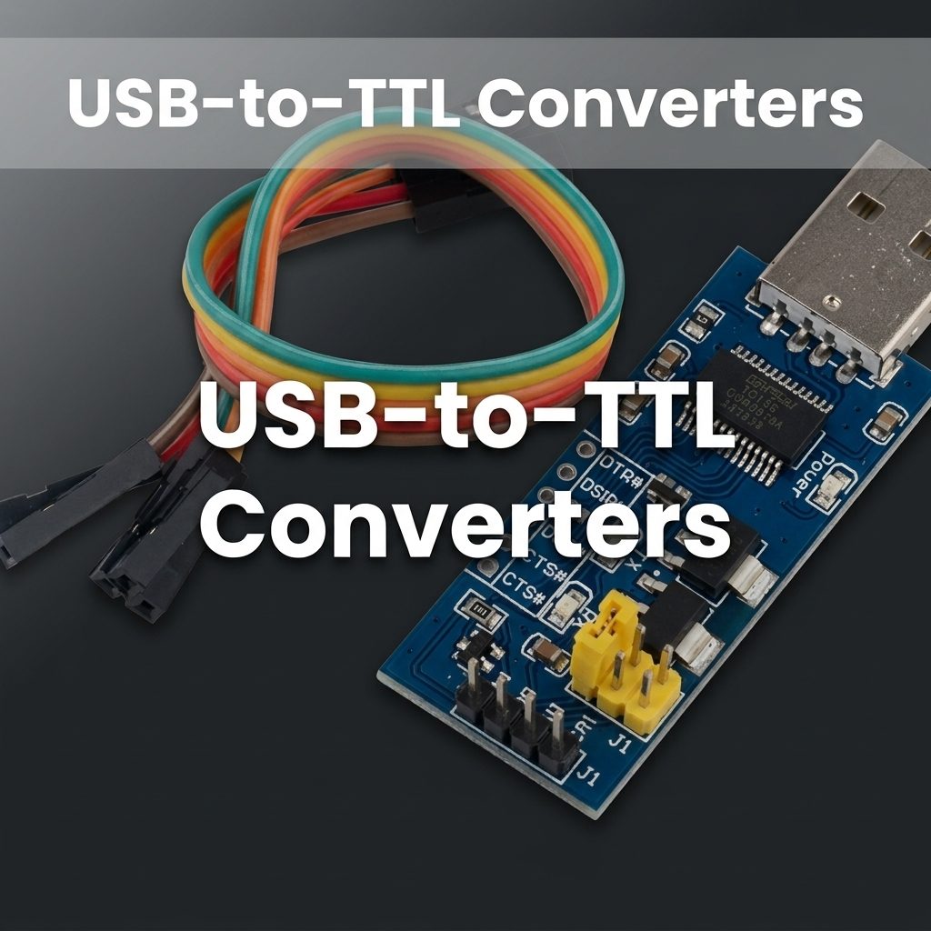
USB-to-TTL Converters
Contents List
- Introduction.
- Understanding TTL Signals.
- What Is USB to TTL?
- Why USB Cannot Connect to TTL Directly?
- Why you might need a USB to TTL converter?
- Common Bridge Chipsets Used in USB-to-TTL Converter.
- Technical Specifications.
- Pin Configuration.
- Wiring and connection basics.
- Driver setup and platform considerations.
- Practical tips when using USB-to-TTL Converter.
- Usage Instructions.
- Common Applications.
- How to choose the right USB to TTL converter?
- Examples Of Projects Built with USB-TLL.
- How to create a USB to serial TTL module by yourself?
- Testing and Troubleshooting basics.
- Frequently Asked Questions (FAQs).
- Conclusion.
Reading time is approximately 15 minutes
Introduction

In the world of electronics development, Efficient data transfer is essential in embedded systems and industrial applications, where reliable communication between devices ensures smooth operation and data integrity. A USB-to-TTL Converter is one of those small tools that quietly unlocks a lot of potential. Whether you are debugging a microcontroller project, flashing a bootloader, or simply adding a console port to a device, a reliable USB to TTL adapter is a must-have in your toolkit.
Understanding TTL Signals
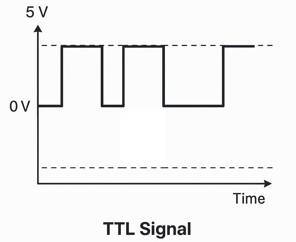
TTL signals are digital and have specific voltage levels. A logic zero is usually about 0V, and a logic 1 is around 3.3V or 5V. These signals are standard in many microcontrollers and embedded systems, making TTL a go-to protocol for serial communication.
What Is USB to TTL?
A USB-to-TTL Converter is a device that bridges the gap between USB interfaces and TTL (Transistor-Transistor Logic) serial communication, allowing seamless data transfer between computers and microcontrollers or other embedded systems. It translates USB signals to TTL levels, making it a crucial tool for developers working with serial communication in various projects. USB to TTL converters are particularly valuable in these settings, enabling precise control and monitoring of connected devices without complex setups.
Why USB Cannot Connect to TTL Directly?
USB and TTL differ at both the protocol and electrical levels:
| USB | TTL (UART) |
|---|---|
| Differential signaling (D+ / D−) | Single-ended TX / RX |
| Complex USB protocol | Simple asynchronous serial |
| Requires USB controller | Direct MCU GPIO |
| Fixed USB rules | Flexible baud rates |
A USB-to-TTL adapter handles protocol conversion, logic-level translation, and communication with the operating system via drivers.
Why you might need a USB to TTL converter?
Here are the most common use cases that explain why these adapters are so popular in both hobbyist and professional circles:
- Debugging microcontrollers and single-board computers — Many microcontrollers boot with a serial console that prints boot messages, debug logs, or prompts for configuration. A USB to TTL adapter provides a direct, stable link to view and send data without the need for a dedicated serial port on your PC.
- Flashing firmware and bootloaders — Some devices require a TTL-level interface to flash bootloaders or load new firmware. A reliable adapter helps ensure a smooth, repeatable flashing process.
- Custom interfaces for hardware prototypes — In test benches, a TTL console or custom serial command interface can simplify instrument control, data capture, and parameter tweaking during development.
- Raspberry Pi and BeagleBone debugging — Although these boards include a built-in serial header, a USB to TTL adapter offers an alternative, convenient way to access the console, especially when the main USB port is occupied.
- Industrial and embedded testing — In manufacturing or field-service scenarios, a portable TTL serial interface can facilitate rapid troubleshooting, configuration, and data retrieval.
Common Bridge Chipsets Used in USB-to-TTL Converter
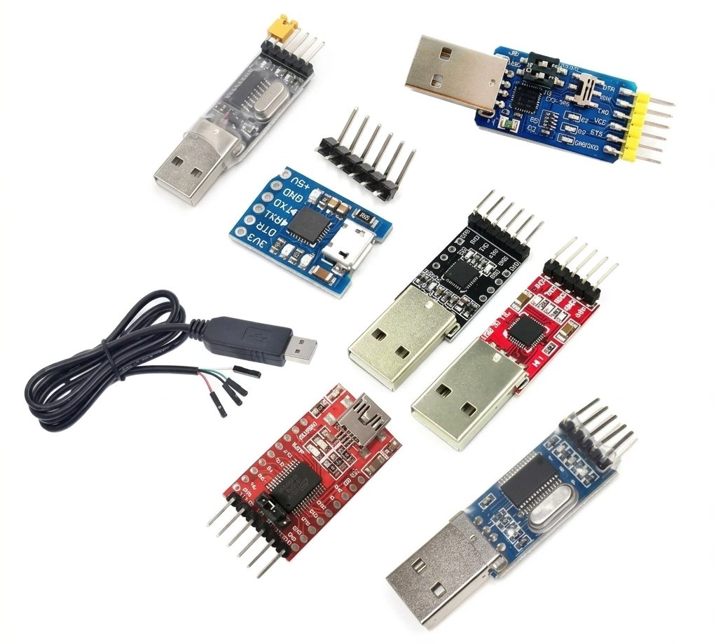
- CH340 – widely used and cost-effective.
- CP2102 – stable and well supported.
- FT232 – industrial-grade reliability.
- PL2303 – older chipset, driver support may vary by OS version.
Technical Specifications
The USB-TTL converter comes in various models, but the following are typical specifications:
| Parameter | Details |
|---|---|
| Input Voltage (USB) | 5V (via USB port) |
| Output Voltage (TTL) | 3.3V or 5V (selectable on some models) |
| Communication Protocol | UART (Universal Asynchronous Receiver-Transmitter) |
| Baud Rate | 300 bps to 3 Mbps (varies by model) |
| Operating Temperature | -40°C to 85°C |
| Connector Type | USB Type-A or Type-C (varies by model) |
| Driver Chipset Used | Commonly FT232RL, CH340, or CP2102 |

Pin Configuration
The USB-TTL converter typically has the following pins:
| Pin Name | Description |
|---|---|
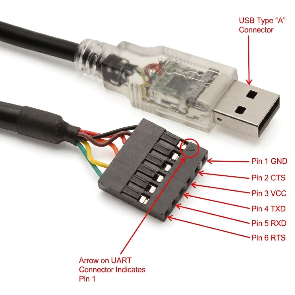
| GND | Ground connection. Connect to the ground of the target device. |
| VCC | Power output. Provides 3.3V or 5V (depending on the model or jumper setting). |
| TXD | Transmit Data. Sends serial data from the USB-TTL converter to the target device. |
| RXD | Receive Data. Receives serial data from the target device to the USB-TTL converter. |
| RTS | Request to Send. Optional pin for hardware flow control (not always used). |
| CTS | Clear to Send. Optional pin for hardware flow control (not always used). |
Wiring and connection basics.
Connecting a USB to TTL adapter to a microcontroller or module is straightforward, but a couple of best practices help ensure a clean, reliable link:
- Identify the right voltage — Check your target device’s logic level. If you are not sure, start with 3.3V and avoid 5V until you confirm compatibility.
- Match TX and RX — Connect the adapter’s TX pin to the device’s RX pin, and the adapter’s RX pin to the device’s TX pin. This cross-over is essential for data to flow in the correct direction.
- Common ground — Tie the ground of the USB adapter to the ground of the target system. Without a common ground, reference levels drift and communication fails.
- Power considerations — If your target device needs power (VCC), use the adapter’s VCC pin only if the target’s current draw is within the adapter’s capability. Otherwise, power the device separately and only use the UART pins for data.
- Control lines for advanced use — DTR and RTS lines can trigger reset or enter bootloader modes on certain boards (e.g., auto-reset for Arduino-style boards). If your board requires it, enable the appropriate line and verify timing in your development environment.
- Cable length and shielding — USB-to-TTL cables are generally short. If you must go longer, choose shielded cables and a robust adapter to minimize noise and data corruption.
Driver setup and platform considerations
Setting up drivers correctly is one of the most critical steps to ensure a smooth experience with USB to TTL converters. The specifics vary by operating system and chipset:
Windows
Most CH340 and CP2102 devices offer Windows drivers that install automatically via Windows Update or come bundled with the driver package. If your device fails to enumerate a COM port, try the following:
- Check Device Manager for any yellow warning icons and update drivers from the vendor site or via Windows Update.
- Uninstall any conflicting drivers that may be installed from a previous adapter.
- Verify the COM port number in Device Manager and adjust the terminal program’s settings accordingly.
macOS
macOS generally supports FTDI-based devices out of the box, and CP2102/CH340 modules often require a driver package. After installation, you will typically use a serial terminal program to connect to /dev/tty.usbserial-xxxx or similar device paths.
Linux
Most Linux distributions include generic drivers for FTDI, CP2102, and CH340 devices. You can often see the device with commands like lsusb and dmesg. The serial device will appear as /dev/ttyUSB0 or /dev/ttyACM0. You may need to add your user to the dialout group to access serial devices without sudo.
Practical tips when using USB-to-TTL Converter
Below are several real-world scenarios that illustrate how USB to TTL converters can streamline development and debugging across popular platforms.
Raspberry Pi and BeagleBone debugging consoles
Many single-board computers expose a UART console for early boot messages, recovery, and headless operation. A USB to TTL adapter is a convenient bridge to access the console without occupying the main USB bus. For Raspberry Pi users, a 3.3V TTL adapter connected to the Pi’s TXD, RXD, and GND pins provides a reliable serial link. If you need to reset the board from software, a DTR or RTS-enabled adapter can automate bootloader entry or safe mode triggers with simple wiring and a little scripting.
Arduino and Microcontroller programming
When programming an Arduino or bare microcontroller, most boards expect a USB-to-serial interface for bootloading and serial monitoring. A good USB to TTL adapter with a stable 3.3V or 5V level, clear labeling, and a convenient way to power the target board makes it simpler to flash firmware, print debug messages, and calibrate sensors in real time.
Industrial and lab testing setups
In industrial testing environments, repeatability and reliability are paramount. Adapters with robust mechanical build quality, protection features, and drivers that are well-supported across Windows, Linux, and macOS help teams standardize their test benches. Having a multi-port adapter can accelerate parallel testing, such as talking to multiple serial instruments, sensors, or microcontrollers in a single workstation setup.
Usage Instructions
How to Use the USB-TTL Converter in a Circuit
Connect the USB-TTL to the Target Device:
- Connect the GND pin of the USB-TTL to the ground of the target device.
- Connect the TXD pin of the USB-TTL to the RX pin of the target device.
- Connect the RXD pin of the USB-TTL to the TX pin of the target device.
- If required, connect the VCC pin to power the target device (ensure voltage compatibility).
Install Drivers:
Install the appropriate driver for the USB-TTL chipset (e.g., FTDI, CH340, or CP2102) on your computer. Drivers are typically available on the manufacturer’s website.
Connect to a Computer:
Plug the USB-TTL converter into a USB port on your computer. Verify that the device is recognized in the Device Manager (Windows) or via the ls /dev/tty* command (Linux/Mac).
Open a Serial Communication Tool:
- Use software like Arduino IDE, PuTTY, or CoolTerm to open a serial connection. Select the correct COM port and baud rate.
Test Communication: - Send and receive data to verify the connection. For example, you can use a loopback test by connecting TXD to RXD and checking if sent data is echoed back.
- Important Considerations and Best Practices
- Voltage Compatibility: Ensure the target device operates at the same voltage level as the USB-TTL converter (3.3V or 5V). Some converters have a jumper or switch to select the voltage.
- Cross-Connection of TX and RX: Always connect the TXD pin of the USB-TTL to the RX pin of the target device, and vice versa.
Driver Installation:
Without the correct driver, the USB-TTL converter may not function properly. Verify the driver installation if issues arise.
Avoid Overloading:
Do not draw excessive current from the VCC pin of the USB-TTL converter, as it is limited by the USB port’s power supply.
Example: Using USB-TTL with Arduino UNO
- The USB-TTL converter can be used to program or communicate with an Arduino UNO.
- Below is an example of how to send data from the Arduino to a computer via the USB-TTL converter.
- Arduino Code Example
// Example: Sending data from Arduino to a computer via USB-TTL
void setup() {
Serial.begin(9600); // Initialize serial communication at 9600 baud
}
void loop() {
Serial.println(“Hello from Arduino!”); // Send a message to the computer
delay(1000); // Wait for 1 second
}
Steps:
Connect the USB-TTL converter to the Arduino:
GND to Arduino GND
TXD to Arduino RX
RXD to Arduino TX
- Open a serial monitor on your computer (e.g., Arduino IDE Serial Monitor).
- Set the baud rate to 9600 and observe the messages sent from the Arduino.
Common Applications
- Programming microcontrollers such as Arduino, ESP8266, and STM32.
- Debugging and monitoring serial data from embedded systems.
- Interfacing with TTL-level devices like GPS modules, GSM modules, and sensors.
- Creating custom USB-to-serial communication tools for projects.
- Firmware flashing and Bootloader access.
- Embedded system development and manufacturing tests.
How to choose the right USB to TTL converter?
Not all USB-to-TTL adapters are created equal. The following features help you choose a model that aligns with your workflow, reliability requirements, and budget:
- Voltage levels (3.3V vs 5V) — TTL logic voltage must match the device you’re connecting. Some boards are 3.3V only, others offer selectable voltage with a switch or jumper. Mismatched voltage can damage the target or result in unreliable communication, so verify compatibility before connecting to your MCU.
- Baud rate range and stability — Most adapters support a wide range (e.g., 300 to 115200 or higher). Look for chips that maintain stable communication at your target rate, especially for long or noisy cables.
- Voltage levels on the VCC pin — Some adapters provide a 3.3V/5V output to power the target device, which can be convenient for breadboard setups. If your project requires external power, confirm the adapter’s power delivery capability.
- Driver availability and OS coverage — Windows, macOS, and Linux compatibility are essential for a universal tool. FTDI and CP2102 often deliver robust, well-supported drivers; CH340 may require occasional driver updates on newer OS versions.
- Jumper wires, form factor, and build quality — A compact module with clear labeling (TX, RX, VCC, GND, DTR, RTS) reduces wiring errors. Durable connectors and a stable PCB reduce wear during repeated use.
- Automatic handshake and control lines — DTR/RTS lines are handy for auto-reset in microcontroller programming (e.g., Arduino-style boards). CTS/RTS can be useful in some advanced protocols or when integrating with other hardware.
- Multi-port options — If you need multiple serial channels, look for two-port or multi-port USB-to-TTL adapters with independent channels for simultaneous monitoring or programming.
- Over-voltage and ESD protection — For industrial environments, protection features can improve longevity in harsh settings.
- Price and warranty — Balance cost against reliability and support. For critical projects, investing in reputable brands and a good warranty can save time and risk later.
Examples Of Projects Built with USB-TLL
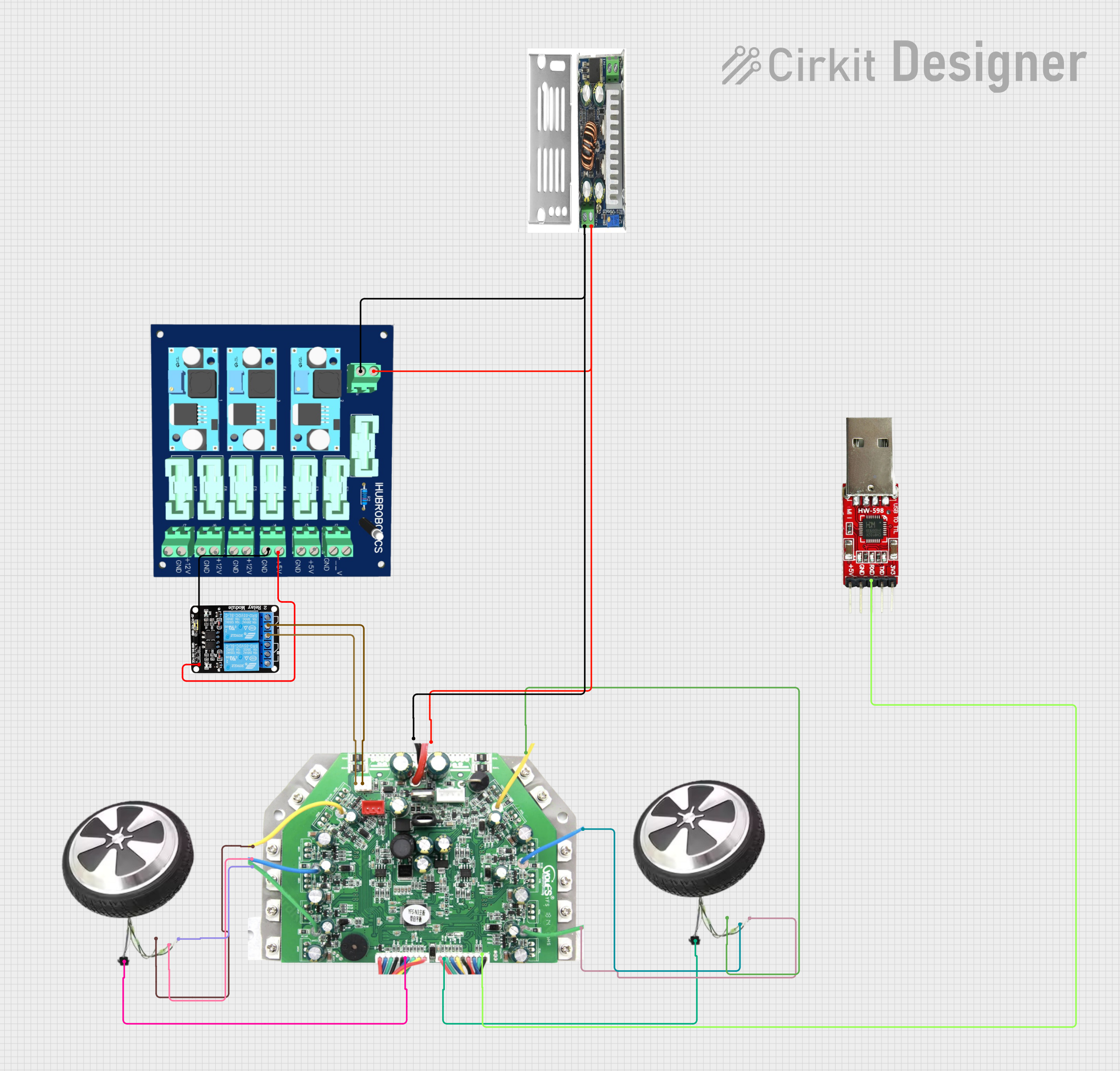
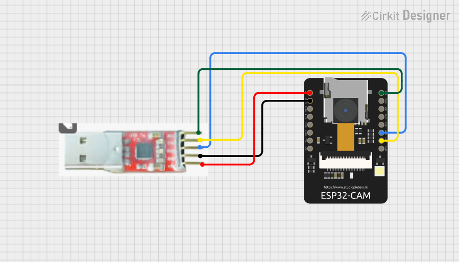
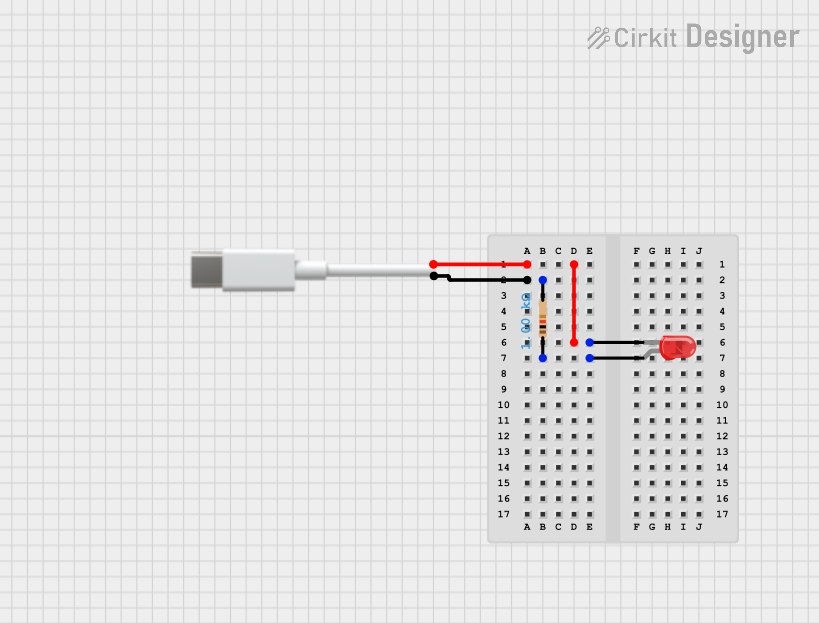
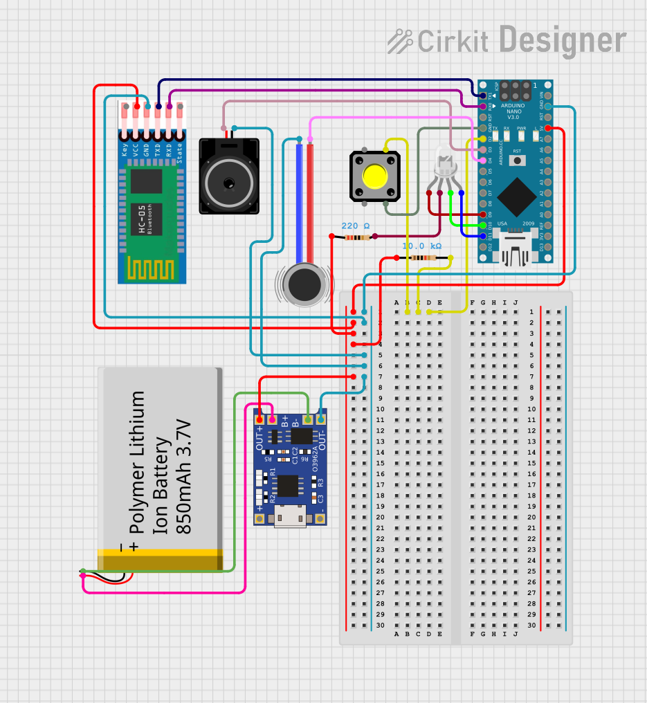
How to create a USB to serial TTL module by yourself?
If you’d like to implement USB-to-TTL Converters yourself, click on this link:
USB to serial TTL module by yourself
Testing and Troubleshooting basics
Even with a good adapter, issues can arise. Here are practical steps to diagnose and fix common problems:
- Perform a loopback test — Connect TX to RX on the adapter itself and transmit data from a terminal program. If you see the same characters echoed back, the basic UART path is functioning correctly.
- Verify baud rate and parity — Ensure the device and the adapter agree on 8 data bits, no parity, and 1 stop bit (8N1) by default, unless your application specifies otherwise.
- Check voltage compatibility — A 5V logic device connected to a 3.3V adapter may fail at higher data rates or operate erratically. Use a level-matched adapter or a device with selectable voltage.
- Inspect wiring and ground reference — A loose connection or missing ground is a frequent cause of garbled data. Re-check the wiring and ensure a solid ground path.
- Driver conflicts — If a device does not enumerate, suspect driver conflicts or blocked kernel modules. On Linux, check dmesg for device creation messages and ensure the correct /dev/tty* path is used.
- Noise and interference — USB cables and long TTL lines can pick up noise. Use shorter cables for higher baud rates and consider shielded cabling in noisy environments.
Frequently Asked Questions (FAQs)
Q: Can I use the USB-TTL converter to power my target device?
A: Yes, but only if the target device’s power requirements are within the limits of the USB-TTL converter and the USB port (typically 500mA for USB 2.0).
Q: What is the maximum baud rate supported?
A: The maximum baud rate depends on the chipset. For example, FT232RL supports up to 3 Mbps, while CH340 supports up to 2 Mbps.
Q: Can I use the USB-TTL converter for SPI or I2C communication?
A: No, the USB-TTL converter is designed for UART communication only. For SPI or I2C, you will need a different interface module.
Q: How do I perform a loopback test?
A: Connect the TXD pin to the RXD pin on the USB-TTL converter. Open a serial terminal, send data, and check if it is echoed back.
By following this documentation, you can effectively use the USB-TTL converter for a wide range of applications.
Conclusion
A USB-to-TTL converter is a simple yet essential tool for connecting computers with microcontrollers, embedded systems, and other UART-based devices. From debugging serial communication and monitoring boot messages to flashing firmware and developing prototypes, it provides a convenient bridge between USB and TTL-level serial interfaces.
When choosing a USB-to-TTL converter, always consider the logic voltage, chipset, baud-rate support, driver compatibility, pin configuration, and protection features. Most importantly, make sure the converter’s voltage levels are compatible with your target device, and always connect TX to RX, RX to TX, and GND to GND.
With the right converter and proper wiring, USB-to-TTL communication can make debugging, programming, testing, and prototyping embedded hardware much easier. Whether you are working with an Arduino, ESP32, Raspberry Pi, STM32, or another UART-enabled device, a good USB-to-TTL converter is a practical addition to any electronics toolkit.
محولات USB الي TTL
محتويات المقال
-
- المقدمة
- فهم إشارات TTL
- ما هو محول USB إلى TTL؟
- لماذا لا يمكن توصيل USB بإشارات TTL مباشرة؟
- لماذا نحتاج إلى محول USB إلى TTL؟
- أشهر الشرائح المستخدمة في محولات USB إلى TTL
- المواصفات الفنية
- توزيع أطراف التوصيل
- أساسيات التوصيل والأسلاك
- إعداد برامج التشغيل ومتطلبات أنظمة التشغيل
- نصائح عملية عند استخدام محول USB إلى TTL
- طريقة استخدام محول USB إلى TTL
- الاستخدامات الشائعة
- كيف تختار محول USB إلى TTL المناسب؟
- أمثلة على مشروعات تعتمد على USB إلى TTL
- كيف تصنع وحدة محول من USB إلى Serial TTL بنفسك؟
- أساسيات الاختبار واستكشاف الأخطاء وإصلاحها
- الأسئلة الشائعة
- الخاتمة
- المقدمة
مدة القراءة: حوالي 15 دقيقة
المقدمة
في عالم تطوير الإلكترونيات، يعد نقل البيانات بشكل موثوق وسريع من الأمور المهمة، خصوصًا عند التعامل مع الأنظمة المدمجة والأجهزة الصناعية. فالاتصال المستقر بين المكونات يساعد على مراقبة البيانات والتحكم في الأجهزة واكتشاف المشكلات أثناء التطوير.
ويأتي محول USB إلى TTL كحل عملي وبسيط لربط الحاسوب بالأجهزة التي لا تحتوي على منفذ تسلسلي تقليدي. ويمكن استخدامه للوصول إلى وحدة التحكم التسلسلية، أو تحميل البرامج الثابتة، أو مراقبة رسائل النظام، أو اختبار الاتصال بين المتحكمات والوحدات الإلكترونية المختلفة.
لذلك يُعد محول USB إلى TTL من الأدوات الأساسية في مجال الإلكترونيات والأنظمة المدمجة، إذ يتيح إنشاء اتصال تسلسلي بين الحاسوب والأجهزة التي تعتمد على واجهة UART بمستويات منطقية TTL.
فهم إشارات TTL
تشير TTL إلى مستويات منطقية كهربائية تُستخدم لتمثيل الإشارات الرقمية. وفي الاتصالات التسلسلية من نوع UART، يتم تمثيل الحالة المنطقية عادةً بمستويات جهد مثل 3.3 فولت أو 5 فولت، وفقًا لنوع الدائرة الإلكترونية المستخدمة.
- المستوى المنطقي المنخفض يكون قريبًا من 0 فولت.
- المستوى المنطقي المرتفع يعتمد على جهد تشغيل الدائرة، وقد يكون 3.3 فولت أو 5 فولت.
- يجب التأكد من توافق مستوى الجهد قبل توصيل المحول بالجهاز المستهدف.
ما هو محول USB إلى TTL؟
محول USB إلى TTL هو دائرة إلكترونية تعمل كواجهة بين منفذ USB الموجود في الحاسوب وواجهة الاتصال التسلسلي UART الموجودة في المتحكمات والأنظمة المدمجة. يقوم المحول بتحويل البيانات القادمة من الحاسوب إلى إشارات تسلسلية بالمستوى المنطقي المناسب للجهاز، والعكس صحيح.
وتكمن أهمية هذه المحولات في أنها توفر طريقة سهلة للوصول إلى المنافذ التسلسلية للأجهزة، دون الحاجة إلى وجود منفذ Serial تقليدي في الحاسوب.
لماذا لا يمكن توصيل USB بإشارات TTL مباشرة؟
لا يمكن عادةً توصيل منفذ USB مباشرةً بأطراف UART الخاصة بالمتحكم، لأن USB وUART يختلفان في طريقة نقل البيانات وفي الخصائص الكهربائية للإشارات.
| USB | UART / TTL |
|---|---|
| يعتمد USB على إشارتين تفاضليتين D+ وD−. | يعتمد UART على خطوط منفصلة مثل TX وRX. |
| يستخدم بروتوكول USB الأكثر تعقيدًا. | يستخدم اتصالًا تسلسليًا غير متزامن. |
| يتطلب وحدة تحكم USB مناسبة. | يمكن للمتحكم التعامل معه عبر وحدة UART. |
| له متطلبات محددة للاتصال وإدارة الأجهزة. | يمكن ضبط سرعة الاتصال وإعداداته وفقًا للجهاز. |
لذلك يقوم محول USB إلى TTL بتوفير الواجهة المناسبة بين النظامين، بحيث يتعامل الحاسوب مع المحول كجهاز USB، بينما يتعامل الجهاز الإلكتروني معه كواجهة UART ذات مستوى منطقي مناسب.
لماذا نحتاج إلى محول USB إلى TTL؟
- تصحيح أخطاء المتحكمات والأنظمة المدمجة: يمكن استخدام المنفذ التسلسلي لمراقبة رسائل النظام، وقراءة بيانات التشخيص، وإرسال أوامر إلى الجهاز.
- تحميل البرامج الثابتة: بعض المتحكمات والوحدات الإلكترونية تعتمد على UART أثناء برمجة البرنامج أو تحميل Bootloader.
- اختبار النماذج الأولية: يمكن استخدام الاتصال التسلسلي لإرسال أوامر واختبار الدوائر والوحدات أثناء مرحلة التطوير.
- الوصول إلى وحدة التحكم: توفر بعض أجهزة الحاسوب أحادية اللوحة منفذ UART يمكن استخدامه للوصول إلى رسائل الإقلاع أو وحدة التحكم الخاصة بالنظام.
- الاختبارات الصناعية والمخبرية: يمكن استخدام المحول للتواصل مع المتحكمات وأجهزة القياس والوحدات التسلسلية أثناء الاختبار والصيانة.
أشهر الشرائح المستخدمة في محولات USB إلى TTL
- CH340: شريحة شائعة ومنخفضة التكلفة، وتتوفر في عدد كبير من المحولات.
- CP2102: تتميز باستقرار جيد ودعم واسع لأنظمة التشغيل المختلفة.
- FT232: من الحلول المعروفة للاستخدامات التي تتطلب اعتمادية جيدة ودعمًا مستقرًا.
- PL2303: شريحة قديمة وشائعة في بعض المحولات، إلا أن توافق برامج التشغيل قد يختلف حسب إصدار نظام التشغيل.
المواصفات الفنية
تختلف المواصفات من محول إلى آخر، ولكن النماذج الشائعة قد تتضمن المواصفات التالية:
| المواصفة | التفاصيل |
|---|---|
| جهد USB | 5 فولت عادةً من منفذ USB. |
| جهد الإشارات المنطقية | 3.3 فولت أو 5 فولت حسب نوع المحول. |
| نوع الاتصال | UART / Serial. |
| سرعة الاتصال | تختلف حسب الشريحة والمحول، وقد تصل إلى سرعات مرتفعة في بعض الطرز. |
| درجة حرارة التشغيل | تختلف حسب الشركة المصنعة والطراز. |
| نوع موصل USB | USB Type-A أو USB Type-C أو غيرهما وفقًا للطراز. |
| الشريحة | مثل FT232 أو CH340 أو CP2102. |
توزيع أطراف التوصيل
| الطرف | الوظيفة |
|---|---|
| GND | الأرضي، ويجب توصيله بأرضي الجهاز المستهدف. |
| VCC | خرج طاقة قد يكون 3.3 فولت أو 5 فولت حسب المحول. |
| TXD | إرسال البيانات من المحول إلى الجهاز. |
| RXD | استقبال البيانات القادمة من الجهاز إلى المحول. |
| RTS | خط اختياري للتحكم في تدفق البيانات. |
| CTS | خط اختياري للتحكم في تدفق البيانات. |
أساسيات التوصيل والأسلاك
- تحقق من جهد الإشارة: تأكد من أن المحول يعمل بالمستوى المنطقي الذي يتوافق مع الجهاز المستهدف.
- اعكس TX وRX: يجب توصيل TX في المحول إلى RX في الجهاز، وRX في المحول إلى TX في الجهاز.
- توصيل الأرضي: يجب أن يكون GND في المحول مشتركًا مع GND في الجهاز.
- الطاقة: لا تستخدم طرف VCC لتغذية الجهاز إلا بعد التأكد من أن المحول قادر على توفير الجهد والتيار المطلوبين.
- خطوط التحكم: قد تكون أطراف DTR أو RTS مفيدة في بعض التطبيقات، مثل إعادة تشغيل المتحكم أو الدخول إلى وضع Bootloader.
- طول الكابل: يفضل استخدام توصيلات قصيرة لتقليل الضوضاء ومشكلات الاتصال، خصوصًا عند السرعات العالية.
تثبيت برامج التشغيل والتوافق مع أنظمة التشغيل
يعتمد التعرف على محول USB إلى TTL على شريحة USB المستخدمة فيه ونظام التشغيل الموجود على الحاسوب. لذلك من المهم التأكد من تثبيت برنامج التشغيل المناسب عند الحاجة.
نظام Windows
- افتح إدارة الأجهزة وتحقق من ظهور منفذ COM الخاص بالمحول.
- في حال ظهور علامة تحذير، تحقق من برنامج التشغيل المناسب للشريحة.
- سجل رقم منفذ COM لاستخدامه في برنامج الاتصال التسلسلي.
نظام macOS
قد تتعرف إصدارات macOS الحديثة على بعض الشرائح تلقائيًا، بينما قد تحتاج بعض المحولات إلى برنامج تشغيل خاص. وبعد التعرف على الجهاز، يظهر المنفذ التسلسلي عادةً ضمن أجهزة النظام التسلسلية.
نظام Linux
تتضمن معظم توزيعات Linux الحديثة دعمًا لعدد كبير من شرائح USB إلى UART. ويمكن التحقق من الجهاز باستخدام أدوات النظام مثل lsusb وdmesg، وقد يظهر المنفذ باسم مثل ttyUSB0 أو ttyACM0 وفقًا لنوع الجهاز وبرنامج التشغيل.
نصائح عملية عند استخدام محول USB إلى TTL
استخدامه مع Raspberry Pi وأجهزة الحاسوب أحادية اللوحة
توفر العديد من أجهزة الحاسوب أحادية اللوحة واجهة UART للوصول إلى رسائل الإقلاع ووحدة التحكم. ويمكن استخدام محول USB إلى TTL للوصول إلى هذه الواجهة بسهولة، مع ضرورة التأكد من مستوى الجهد المناسب للجهاز قبل إجراء أي توصيل.
استخدامه مع Arduino والمتحكمات الدقيقة
يمكن استخدام المحول لإرسال واستقبال البيانات التسلسلية، ومراقبة الرسائل التي يرسلها المتحكم، وفي بعض الحالات تحميل البرامج الثابتة أو التعامل مع Bootloader.
استخدامه في المختبرات والاختبارات الصناعية
في بيئات الاختبار، تكون الاعتمادية والاستقرار عاملين أساسيين. لذلك يفضل اختيار محولات تتمتع بجودة تصنيع جيدة، وحماية مناسبة، ودعم مستقر لأنظمة التشغيل المستخدمة.
طريقة استخدام محول USB إلى TTL
توصيل المحول بالجهاز المستهدف
- وصل GND في المحول مع GND في الجهاز.
- وصل TXD في المحول مع RX في الجهاز.
- وصل RXD في المحول مع TX في الجهاز.
- وصل VCC فقط إذا كان الجهاز يحتاج إلى التغذية من المحول وكان الجهد والتيار مناسبين.
تثبيت برنامج التشغيل
ثبّت برنامج التشغيل المناسب لشريحة المحول إذا لم يتعرف نظام التشغيل عليه تلقائيًا، ثم تأكد من ظهور منفذ الاتصال التسلسلي.
توصيل المحول بالحاسوب
بعد توصيل المحول بمنفذ USB، تحقق من ظهور الجهاز في نظام التشغيل وسجل اسم أو رقم المنفذ التسلسلي الذي تم تخصيصه له.
فتح برنامج الاتصال التسلسلي
استخدم برنامجًا مناسبًا للاتصال التسلسلي، مثل Arduino IDE أو PuTTY أو CoolTerm، ثم اختر المنفذ الصحيح واضبط سرعة الاتصال والإعدادات المطلوبة.
اختبار الاتصال
يمكن اختبار المحول باستخدام Loopback Test عن طريق توصيل TXD مع RXD وإرسال بيانات من برنامج الاتصال. إذا ظهرت البيانات نفسها مرة أخرى، فهذا يدل على أن مسار الاتصال الأساسي يعمل.
مثال على استخدام USB إلى TTL مع Arduino UNO
يمكن استخدام محول USB إلى TTL للتواصل التسلسلي مع Arduino UNO. وفي حالة استخدام واجهة UART، يتم توصيل خطوط الإرسال والاستقبال بشكل متقاطع.
| المحول | Arduino UNO |
|---|---|
| GND | GND |
| TXD | RX |
| RXD | TX |
مثال بسيط لإرسال رسالة تسلسلية كل ثانية:
void setup() {
  Serial.begin(9600);
}

void loop() {
  Serial.println("Hello from Arduino!");
  delay(1000);
}
بعد تشغيل البرنامج، افتح Serial Monitor واضبط سرعة الاتصال على 9600 بت في الثانية لمشاهدة الرسائل المرسلة من Arduino.
الاستخدامات الشائعة
- برمجة المتحكمات الدقيقة مثل Arduino وESP8266 وESP32 وSTM32.
- مراقبة البيانات التسلسلية وتصحيح أخطاء الأنظمة المدمجة.
- التواصل مع وحدات GPS وGSM وبعض الحساسات والوحدات التسلسلية.
- الوصول إلى Bootloader وتحميل البرامج الثابتة.
- إجراء اختبارات التصنيع والصيانة للأجهزة الإلكترونية.
- إنشاء واجهات تسلسلية مخصصة للمشروعات الإلكترونية.
كيف تختار محول USB إلى TTL المناسب؟
- مستوى الجهد: تأكد من أن مستوى الإشارة 3.3 فولت أو 5 فولت متوافق مع الجهاز المستهدف.
- سرعة الاتصال: تحقق من أن المحول يدعم سرعة UART التي يحتاج إليها مشروعك.
- خرج الطاقة: إذا كنت تخطط لتغذية الجهاز من المحول، تحقق من قدرة VCC على توفير التيار المطلوب.
- دعم أنظمة التشغيل: اختر شريحة تتمتع ببرامج تشغيل مستقرة ومتوافقة مع نظام التشغيل الذي تستخدمه.
- جودة التصنيع: المحول الجيد يكون واضح العلامات وسهل التوصيل ومناسبًا للاستخدام المتكرر.
- أطراف التحكم: وجود DTR وRTS قد يكون مفيدًا في بعض مشروعات البرمجة وإعادة التشغيل التلقائي.
- الحماية: في الاستخدامات الصناعية، يفضل اختيار محول مزود بحماية من زيادة الجهد والتفريغ الكهروستاتيكي عند توفرها.
- السعر والضمان: لا تعتمد على السعر وحده؛ فالمحول الأكثر موثوقية قد يوفر وقتًا وجهدًا كبيرين في المشروعات المهمة.
أمثلة على مشروعات باستخدام USB إلى TTL
يمكن استخدام محولات USB إلى TTL في مجموعة متنوعة من المشروعات الإلكترونية، مثل أنظمة التحكم بالمحركات، وبرمجة وحدات ESP32، ومشروعات Arduino، واختبار الوحدات التسلسلية.
نظام تحكم بمحركين Hub Motor باستخدام واجهة USB إلى TTL وريليه للتبديل
صُمم هذا المشروع للتحكم في محركين من نوع Hub Motor من خلال وحدة تحكم مخصصة للمحركات، مع تزويد النظام بالطاقة عبر محول DC-DC ووحدة طاقة مناسبة.
يوفر محول USB إلى TTL اتصالًا تسلسليًا بين الحاسوب ووحدة التحكم بالمحركات، مما يتيح إرسال أوامر التحكم ومتابعة الاتصال مع وحدة التشغيل.
كما تتضمن الدائرة وحدة ريليه بجهد 5 فولت للتحكم في تشغيل المحركين وإيقافهما حسب الحاجة.
وحدة ESP32-CAM مع الاتصال عبر USB إلى TTL
توضح هذه الدائرة كيفية توصيل وحدة ESP32-CAM بمحول USB إلى TTL لتوفير الاتصال التسلسلي والطاقة اللازمة لتشغيل الوحدة.
يتم توصيل طرف الإرسال VOT وطرف الاستقبال VOR في وحدة ESP32-CAM بالطرفين RXD وTXD في محول USB إلى TTL على التوالي، مما يسمح بتبادل البيانات التسلسلية بين وحدة ESP32-CAM والحاسوب المتصل بها.
كما تتضمن التوصيلات خطوط التغذية 3V3 و5V بالإضافة إلى خط الأرضي GND بين الوحدتين، لضمان حصول وحدة ESP32-CAM على التغذية المناسبة وتمكينها من التواصل مع الحاسوب عبر واجهة USB إلى TTL.
دائرة LED تعمل عبر USB Type-C مع مقاومة
تتكون هذه الدائرة من منفذ USB Type-C لتوفير الطاقة اللازمة لتشغيل LED أحمر، مع توصيل مقاومة بقيمة 1000 أوم على التوالي مع الـLED.
تعمل المقاومة على الحد من مقدار التيار المار عبر الـLED وحمايته من التيار الزائد. وعند توصيل الدائرة بمصدر الطاقة، يمر التيار عبر المقاومة ثم يضيء الـLED الأحمر.
كيف تصنع وحدة USB إلى Serial TTL بنفسك؟
إذا كنت ترغب في تصميم محول USB إلى Serial TTL بنفسك،
فقم بالضغط علي هذا الرابط طريقة عمل محول USB الي TTL بنفسك
الاختبار واستكشاف الأخطاء وإصلاحها
- اختبار Loopback: صل TXD مع RXD في المحول نفسه، ثم أرسل نصًا من برنامج الاتصال. إذا عاد النص نفسه، فهذا مؤشر جيد على عمل الاتصال الأساسي.
- مراجعة سرعة الاتصال: تأكد من تطابق Baud Rate بين المحول والجهاز المستهدف.
- مراجعة إعدادات UART: تحقق من عدد بتات البيانات، والتكافؤ، وعدد بتات التوقف. الإعداد الشائع هو 8N1.
- فحص الجهد: تأكد من أن مستوى الجهد المنطقي للمحول مناسب للجهاز المتصل به.
- فحص التوصيلات: تأكد من أن TX متصل بـ RX، وRX متصل بـ TX، وأن GND مشترك بين الجهازين.
- فحص برنامج التشغيل: إذا لم يظهر المحول في نظام التشغيل، تحقق من برنامج التشغيل المناسب للشريحة المستخدمة.
- تقليل الضوضاء: استخدم أسلاكًا قصيرة وتجنب تمرير خطوط UART بالقرب من مصادر الضوضاء الكهربائية القوية.
الأسئلة الشائعة حول محولات USB إلى TTL
هل يمكن استخدام محول USB إلى TTL لتغذية الجهاز المستهدف بالطاقة؟
نعم، ولكن فقط إذا كان المحول قادرًا على توفير الجهد والتيار اللذين يحتاج إليهما الجهاز. لا تفترض أن طرف VCC في المحول مناسب لتغذية أي جهاز دون الرجوع إلى مواصفات المحول والجهاز.
ما أعلى سرعة اتصال يمكن أن يدعمها المحول؟
تعتمد السرعة القصوى على شريحة USB إلى UART والطراز المستخدم. بعض المحولات تدعم سرعات تتجاوز 1 ميجابت في الثانية، بينما تختلف الحدود الفعلية من شريحة إلى أخرى.
هل يمكن استخدام USB إلى TTL مع SPI أو I2C؟
محول USB إلى TTL التقليدي مصمم أساسًا للاتصال التسلسلي UART. إذا كنت تريد التواصل باستخدام SPI أو I2C، فستحتاج إلى واجهة أو محول يدعم البروتوكول المطلوب.
كيف يمكن إجراء اختبار Loopback؟
افصل المحول عن الجهاز المستهدف، ثم صل TXD مع RXD على المحول نفسه. افتح برنامجًا للاتصال التسلسلي وأرسل بعض الأحرف. إذا ظهرت الأحرف نفسها في نافذة الاستقبال، فهذا يعني أن مسار الإرسال والاستقبال في المحول يعمل بشكل صحيح.
الخاتمة
محول USB إلى TTL هو أداة صغيرة لكنها مهمة جدًا في تطوير الإلكترونيات والأنظمة المدمجة. فهو يوفر وسيلة عملية للتواصل بين الحاسوب والمتحكمات والأجهزة التي تعتمد على واجهة UART، ويساعد في البرمجة، ومراقبة البيانات، وتصحيح الأخطاء، واختبار النماذج الأولية.
وعند اختيار المحول المناسب، يجب التركيز على مستوى الجهد، والشريحة المستخدمة، وسرعة الاتصال، وتوافق برامج التشغيل، ونوع أطراف التوصيل، وميزات الحماية، وقدرة خرج الطاقة إذا كان سيتم استخدامه لتغذية الجهاز.
والأهم من ذلك هو التأكد من توافق الجهد بين المحول والجهاز المستهدف، وتوصيل TX مع RX وRX مع TX وGND مع GND. ومع التوصيل الصحيح، يصبح محول USB إلى TTL وسيلة فعالة لتسهيل برمجة الأجهزة الإلكترونية واختبارها ومراقبتها واستكشاف مشكلاتها.


Leave a comment
You must be logged in to post a comment.