


Contents
- PC817 – general characteristics of the circuit
- PC817 – pinout description
- PC817 – replacements and other variants
- PC817 – practical applications of the optocoupler
- PC817 – optocoupler parameters
- PC817 – applications in electronics
PC817 – general characteristics of the circuit
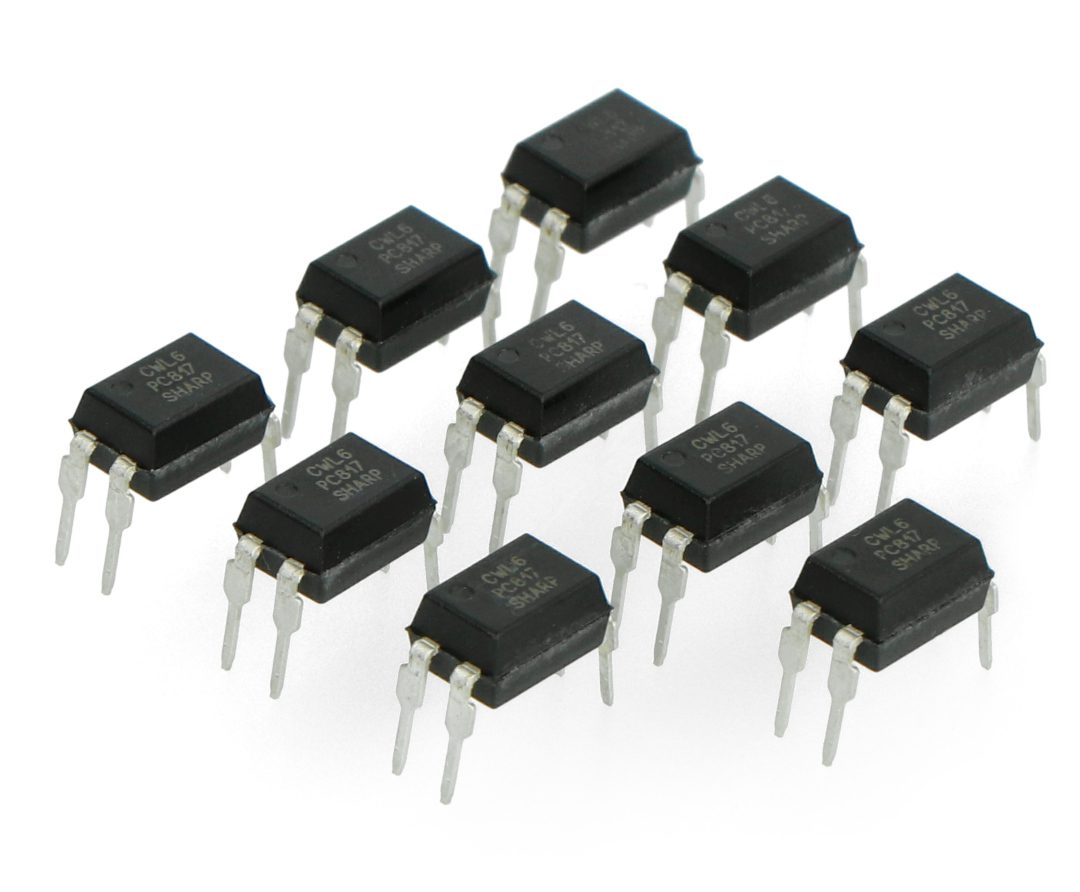
The PC817 is an opto-isolator, also known as an optocoupler. It is commonly used to enable signal transfer between two isolated circuits while providing electrical isolation. Here are the general characteristics of the PC817:
- Structure: The PC817 consists of a light-emitting diode (LED) and a phototransistor, encapsulated in a single package. The LED emits light when forward biased, and the phototransistor is activated by the light emitted from the LED.
- Isolation: It provides electrical isolation between input and output, typically rated at 5,000 volts, making it suitable for protecting sensitive components from high voltages.
- Current Transfer Ratio (CTR): The CTR is a key parameter, representing the ratio of the output current (phototransistor) to the input current (LED). For the PC817, the typical CTR is between 50% to 600%, depending on the model and operating conditions.
- Input/Output Voltage: The forward voltage (V_f) of the LED is typically around 1.2 to 1.4 volts. The phototransistor can handle a collector-emitter voltage (V_ce) of up to 80 volts.
- Switching Speed: The typical rise and fall times for the output signal are relatively quick, allowing it to be effective in high-frequency applications, though it is not as fast as some advanced opto-isolators.
- Applications: Common uses include signal isolation in microcontroller circuits, enabling communication between different voltage domains, and protecting sensitive devices in industrial and consumer applications.
When using the PC817, it’s crucial to consider the required input and output parameters for your specific application to ensure effective isolation and performance.
PC817 – pinout description
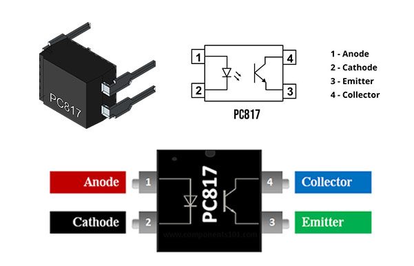
- Pin 1 (Anode of LED): This pin connects to the positive side of the input signal. It is the anode of the internal LED.
- Pin 2 (Cathode of LED): This pin connects to the negative side of the input signal (usually ground). It is the cathode of the internal LED.
- Pin 3 (Collector of Phototransistor): This pin is connected to the positive voltage supply (Vcc) of the output circuit and is the collector of the phototransistor.
- Pin 4 (Emitter of Phototransistor): This pin connects to the ground of the output circuit and is the emitter of the phototransistor.
PC817 – replacements and other variants
4N25, 6N136, MOC3021, MOC3041 as well as 6N137.
PC817 – practical applications of the optocoupler
The PC817 optocoupler is widely used in various applications due to its ability to provide electrical isolation between circuits. Here are some practical applications of the PC817:
- Microcontroller Interfacing: Used to isolate microcontroller outputs from high voltage or noisy environments, protecting sensitive microcontroller circuits while allowing communication with external devices.
- Signal Isolation: Provides isolation for control signals in automation systems, ensuring safe operation while protecting microcontrollers or low-voltage components from high voltage spikes.
- Switching Power Supplies: Utilized in feedback loops for power supply circuits to provide voltage regulation while maintaining electrical isolation between the high-voltage input and low-voltage output.
- Sensor Applications: Used to isolate sensors (e.g., temperature or current sensors) from the conditioning circuitry, allowing safe measurement of physical parameters without direct electrical connection.
- Relay Driving: Often deployed to control relays, allowing low-current control signals to switch higher-power loads while maintaining isolation.
- Telecommunication Systems: Used in signal transmission applications to prevent ground loops and ensure that different sections of a system can operate safely and independently.
- Data Communication: Employed in data communication systems, including RS-232 or RS-485 interfaces, to isolate and protect different segments of communication networks.
- Test and Measurement Equipment: Often found in test equipment for monitoring or measuring AC voltages, providing isolation between the measuring circuits and the high-voltage system under test.
- Audio Applications: Used for isolating audio signals in mixing and processing equipment, preventing noise and interference from electrical ground differences.
- Industrial Control Systems: Commonly utilized in industrial automation to interface between control systems and high-power drives or motors, ensuring safe operation under varying load conditions.
PC817 – optocoupler parameters
- Maximum collector-emitter voltage: 80V
- Maximum collector current: 50mA
- Limit frequency: 80 kHz
- Propagation time: 18us
- Maximum operating temperature: -30°C – +100°C
- Maximum soldering temperature: 260°C
- Storage temperature: -55°C – 125°C
- Maximum power dissipated: 200mW
- Internal resistance: 100R
PC817 – applications in electronics
- The PC817 optocoupler has a very wide range of applications.
- Among other things, it can be used in protection such as electrical isolation between the control stage and the power stage in frequency converters.
- The PC817 is a very efficient circuit when controlled from microcontrollers.
- Simple transistors can be used in addition, but because of the omitted noise factor, the optocoupler can also be used as a switch in high-frequency circuits such as frequency converters and other power electronics.
المحتويات
- PC817 – الخصائص العامة للدائرة المتكاملة
- PC817 – الوصف التفصيلي لأطراف التوصيل (Pinout)
- PC817 – البدائل والإصدارات الأخرى المتوافقة
- PC817 – التطبيقات العملية للمستقبل الضوئي (Optocoupler)
- PC817 – المواصفات والمقاييس الفنية للمستقبل الضوئي
- PC817 – تطبيقات عامة في مجال الإلكترونيات
PC817 – الخصائص العامة للدائرة المتكاملة
- يُعرف العنصر الإلكتروني PC817 بالعازل الضوئي (Opto-isolator) أو المستقبل الضوئي (Optocoupler)، ويُستخدم بشكل أساسي لنقل الإشارات الكهربائية بين دائرتين معزولتين تماماً لتوفير حماية كهربائية متكاملة. وفيما يلي استعراض لأبرز خصائصه العامة:
- البنية الداخلية: يتكون رقاقة PC817 من ثنائي باعث للضوء (LED) وترانزستور ضوئي (Phototransistor) مدمجين معاً داخل عبوة واحدة مغلقة. يبعث الثنائي الضوء عند انحيازه أماميّاً، ليقوم الضوء المتولد بتحفيز وتفعيل الترانزستور الضوئي للعمل.
- العزل الكهربائي: يوفر العنصر عزلاً كهربائياً كاملاً بين دائرة الدخل ودائرة الخرج يصل عادةً إلى 5000 فولت، مما يجعله خياراً مثالياً لحماية المكونات الحساسة من الارتفاع المفاجئ في الجهد الكهربائي.
- نسبة نقل التيار (CTR): تُعد نسبة نقل التيار (Current Transfer Ratio) من المعاملات المحورية، وهي تمثل النسبة بين تيار الخرج (الخاص بالترانزستور الضوئي) إلى تيار الدخل (الخاص بالثنائي الباعث). تتراوح هذه النسبة في PC817 عادةً بين 50% إلى 600%، بناءً على إصدار الشريحة وظروف التشغيل.
- جهد الدخل والخرج: يبلغ الجهد الأمامي (V_f) للثنائي الباعث للضوء حوالي 1.2 إلى 1.4 فولت، في حين يستطيع الترانزستور الضوئي تحمل جهد بين المجمع والمشع (V_ce) يصل إلى 80 فولت كحد أقصى.
- سرعة الاستجابة والتحويل: يتميز زمن الصعود والهبوط لإشارة الخرج بالسرعة الكافية التي تجعله فعالاً في تطبيقات الترددات المتوسطة والعالية، بالرغم من وجود عوازل ضوئية أخرى متطورة تفوقه في السرعة القصوى.
- مجالات الاستخدام: تشمل الاستخدامات الشائعة عزل الإشارات في دوائر المعالجات الدقيقة والمتحكمات، وتأمين الاتصال بين نطاقات جهد مختلفة، وحماية الأجهزة الحساسة في التطبيقات الصناعية والاستهلاكية.
- عند دمج عنصر PC817 في التصميم، يُوصى بدراسة قيم الدخل والخرج المطلوبة بدقة لضمان الحصول على أعلى كفاءة عزل وأفضل أداء مستقر للدائرة.
PC817 – الوصف التفصيلي لأطراف التوصيل (Pinout)
- الطرف 1 (أنود الثنائي الباعث – Anode): يُوصل هذا الطرف بالقطب الموجب لإشارة الدخل، ويمثل مصعد الثنائي الضوئي الداخلي.
- الطرف 2 (كاثود الثنائي الباعث – Cathode): يُوصل بالقطب السالب لإشارة الدخل (الطرف الأرضي عادةً)، ويمثل مهبط الثنائي الضوئي الداخلي.
- الطرف 3 (المجمع للترانزستور – Collector): يُوصل بمصدر الجهد الموجب (Vcc) الخاص بدائرة الخرج المعزولة، ويمثل مجمع الترانزستور الضوئي.
- الطرف 4 (المشع للترانزستور – Emitter): يُوصل بالطرف الأرضي (Ground) الخاص بدائرة الخرج، ويمثل مشع الترانزستور الضوئي الداخلي.
مخطط يوضح الترتيب الداخلي لأطراف التوصيل الأربعة للعازل الضوئي PC817 متضمناً الثنائي والترانزستور.
PC817 – البدائل والإصدارات الأخرى المتوافقة
- يمكن الاعتماد على مجموعة من البدائل المكافئة في حال عدم توفر الشريحة، ومن أبرزها: 4N25, 6N136, MOC3021, MOC3041 بالإضافة إلى العازل عالي السرعة 6N137
PC817 – التطبيقات العملية للمستقبل الضوئي (Optocoupler)
- يُستخدم الحايل الضوئي PC817 على نطاق واسع في الأنظمة الإلكترونية بفضل كفاءته العالية في فصل الدوائر كهربائياً. إليك أبرز تطبيقاته العملية:
- ربط المتحكمات الدقيقة (Microcontroller Interfacing): يُستخدم لعزل منافذ خرج المتحكم الدقيق عن البيئات ذات الجهد العالي أو التي تحتوي على ضوضاء كهربائية (Noise)، مما يحمي الدوائر الحساسة مع الحفاظ على استمرار تبادل البيانات مع الأجهزة الخارجية.
- عزل الإشارات (Signal Isolation): يعمل على عزل إشارات التحكم داخل أنظمة الأتمتة والتحكم الآلي، لضمان تشغيل آمن وحماية المكونات من طفرات الجهد المفاجئة (Voltage Spikes).
- مصادر التغذية الكهربائية ذات المفاتيح (SMPS): يُدمج في دوائر التغذية الراجعة (Feedback Loops) لضبط وتنظيم قراءة الجهد، مع الإبقاء على العزل التام بين مرحلة الدخل ذات الجهد المرتفع ومرحلة الخرج ذات الجهد المنخفض.
- أنظمة الحساسات والمستشعرات: يُستعمل لفصل المستشعرات (مثل مستشعرات الحرارة أو التيار) عن دوائر معالجة الإشارات، مما يتيح قياس المتغيرات الفيزيائية بأمان دون اتصال كهربائي مباشر.
- قيادة المرحلات (Relay Driving): يُعتمد عليه للتحكم في الريلايهات، حيث يسمح لإشارات التحكم ذات التيار المنخفض بفتح وغلق الأحمال ذات القدرات العالية بأمان كامل.
- أنظمة الاتصالات البعيدة: يُدمج في مسارات نقل الإشارات لمنع تشكل حلقات التأريض الأرضية (Ground Loops) وضمان عمل قطاعات النظام المختلفة بشكل مستقل وآمن.
- اتصالات البيانات الرقمية: يُستخدم في شبكات نقل البيانات، مثل واجهات RS-232 أو RS-485، لعزل وحماية أجزاء الشبكة المختلفة من التداخلات الكهربائية الخارجية.
- أجهزة الفحص والقياس: يتواجد في معدات الاختبار لمراقبة وقياس جهود التيار المتردد (AC)، حيث يوفر حاجز عزل آمن بين دوائر القياس الدقيقة والجهود المرتفعة تحت الاختبار.
- الأنظمة الصوتية (Audio Applications): يعمل على عزل الإشارات الصوتية داخل أجهزة المزج والمعالجة (Mixers)، مانعاً حدوث الضوضاء والتشويش الناتج عن اختلاف جهد التأريض.
- أنظمة التحكم الصناعية: يُستعين به في المصانع لربط دوائر التحكم المنخفضة مع مشغلات المحركات ذات القدرات العالية، لضمان استقرار التشغيل تحت ظروف الأحمال المتغيرة.
PC817 – المواصفات والمقاييس الفنية للمستقبل الضوئي
- أقصى جهد بين المجمع والمشع (V_ce): 80 فولت
- أقصى تيار للمجمع (I_c): 50 مللي أمبير
- التردد الحرج للقطع (Cut-off Frequency): 80 كيلوهرتز
- زمن انتشار الإشارة (Propagation Time): 18 ميكروثانية
- نطاق درجة حرارة التشغيل: من -30 درجة مئوية إلى +100 درجة مئوية
- أقصى درجة حرارة عند اللحام: 260 درجة مئوية
- درجة حرارة التخزين الآمنة: من -55 درجة مئوية إلى 125 درجة مئوية
- أقصى قدرة مبددة (Power Dissipation): 200 مللي واط
- المقاومة الداخلية الشائعة: 100 أوم
PC817 – تطبيقات عامة في مجال الإلكترونيات
تنوع واسع في تكنولوجيا العزل الإلكتروني
- يمتاز مكافئ PC817 بمرونة بالغة في دمج الدوائر؛ حيث يُستفاد منه كعنصر حماية رئيسي لعمل فصل تام بين مرحلة التحكم الإشرافية منخفضة الجهد ومرحلة القدرة والتغذية في محولات التردد (Frequency Converters).
الكفاءة مع المتحكمات الدقيقة وإلكترونيات القدرة
- تُبدي هذه الشريحة أداءً فائق الكفاءة عند قيادتها مباشرة بواسطة المتحكمات الدقيقة.
- على الرغم من إمكانية الاستعانة بالترانزستورات العادية كبدائل مفاتيح، إلا أن الميزة الجوهرية للمستقبل الضوئي تكمن في إلغاء وتلاشي معامل الضوضاء الكهربائية تماماً، مما يتيح استخدامه كمفتاح إلكتروني موثوق في دوائر الترددات المرتفعة ومحولات الطاقة ومختلف تطبيقات إلكترونيات القدرة (Power Electronics).


Leave a comment
You must be logged in to post a comment.