


Resistors: Color Code, SMD Codes and How to Choose the Right One
Contents List
- Introduction.
- What Is a Resistor?.
- Types of Resistors.
- How to Read the Resistor Color Code.
- How to Read SMD Resistor Codes.
- Standard Values and Tolerance.
- Power Rating (Wattage).
- Choosing a Resistor for an LED.
- Pull-up and Pull-down Resistors.
- Voltage Divider.
- Resistors in Series and in Parallel.
- How to Measure a Resistor with a Multimeter.
- Common Mistakes to Avoid.
- Starter Values to Keep in Your Kit.
- Frequently Asked Questions.
- Conclusion.
Time reading is 15min.
1. Introduction
Almost every circuit contains resistors. They limit current, set voltages, protect LEDs and microcontroller pins, and pull inputs to a known level. They cost very little, but the wrong value or power rating is one of the most common reasons a beginner’s circuit misbehaves or a part gets hot.
This guide explains what a resistor does, how to read the color bands on through-hole resistors and the number codes on SMD chips, how to choose a value and a power rating, and how to use resistors in the three jobs you will meet first: protecting an LED, pulling up a button input, and dividing a voltage. Every section has worked numbers that you can check with a multimeter.
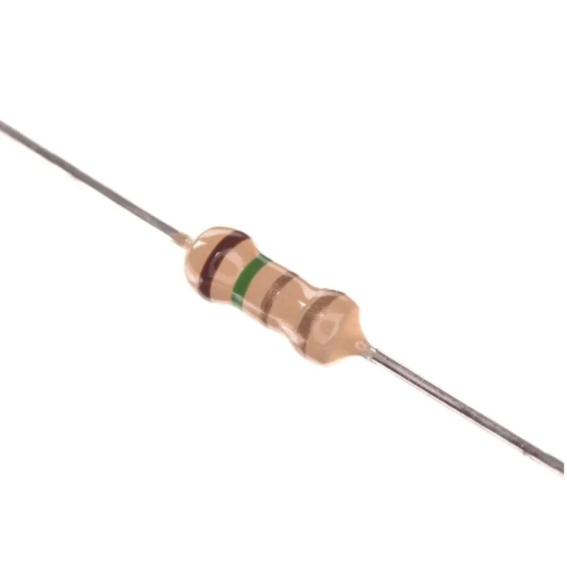
Carbon Resistor 10kΩ 0.25W Through Hole

Chip Resistor SMD 1kΩ ±1% 0.125W ±100ppm/℃ 0805

Chip Resistor SMD 1kΩ ±5% 0.25W ±100ppm/℃ 1206

Power Resistor 20W 20Ω
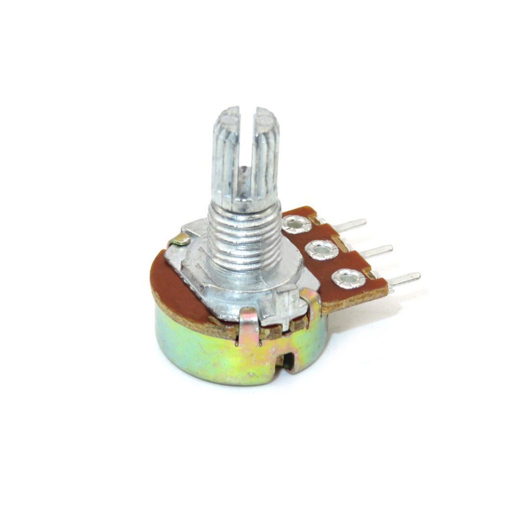
Metal Potentiometer 10KΩ 3-Pin
2. What Is a Resistor?
A resistor is a component that opposes the flow of electric current. Its value is measured in ohms (Ω). Larger values use kΩ (1,000 Ω) and MΩ (1,000,000 Ω). A resistor has no polarity, so it works the same in either direction.
Three relationships cover most of what you need (Ohm’s law and the power formula):
- V = I × R: the voltage across a resistor equals the current through it times its resistance. Rearranged, I = V ÷ R and R = V ÷ I.
- P = V × I = I² × R = V² ÷ R: the power the resistor turns into heat, in watts.
Example: 5 V across a 1 kΩ resistor gives I = 5 ÷ 1000 = 5 mA, and P = 5 × 0.005 = 0.025 W. That is far below the 0.25 W rating of a common through-hole resistor, so it stays cool.
3. Types of Resistors
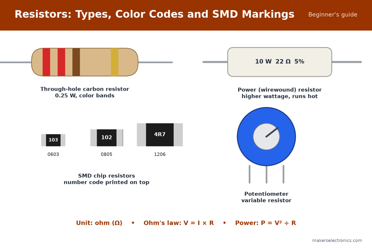
Resistors come in a few physical forms. Pick the form that matches how you build the circuit:
| Type | Typical use | Browse |
|---|---|---|
| Through-hole (axial) carbon or metal film | Breadboards, prototypes, learning kits, general circuits | 0.25 W through-hole resistors |
| SMD chip (0603, 0805, 1206) | Finished PCBs, compact designs, machine assembly | SMD resistors |
| Power (wirewound or ceramic) | High-current paths, dummy loads, braking and heating | Power resistors |
| Potentiometer and trimmer | Adjustable value: volume, calibration, sensor input | Potentiometers |
Carbon film vs metal film
Carbon film resistors are the common low-cost choice. They are usually ±5% and use four color bands. Metal film resistors are usually ±1% or better, have lower noise and drift less with temperature, and usually use five bands. For LEDs and pull-ups ±5% is fine. For voltage dividers that feed an ADC, filters or measurement circuits, use ±1%.
For measuring current there are special very-low-value parts. See our guide to current sense resistors.
4. How to Read the Resistor Color Code
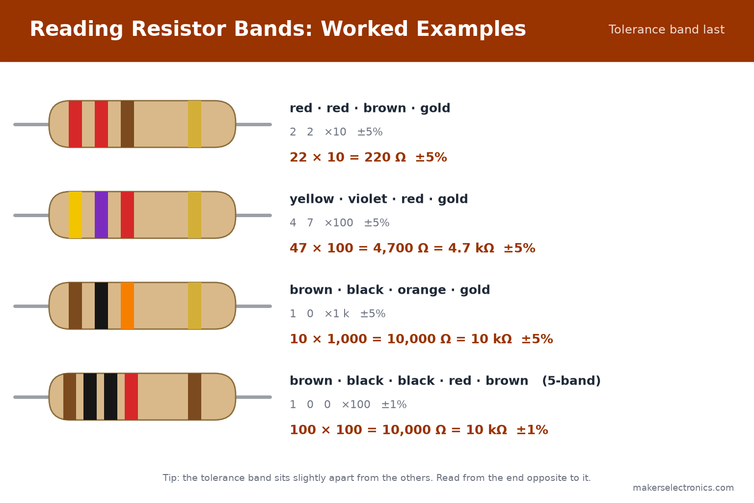
Through-hole resistors are too small to print numbers on, so they use colored bands. A four-band resistor has two digits, a multiplier and a tolerance. A five-band resistor has three digits, a multiplier and a tolerance. The standard is described in IEC 60062 and summarized in this electronic color code reference.
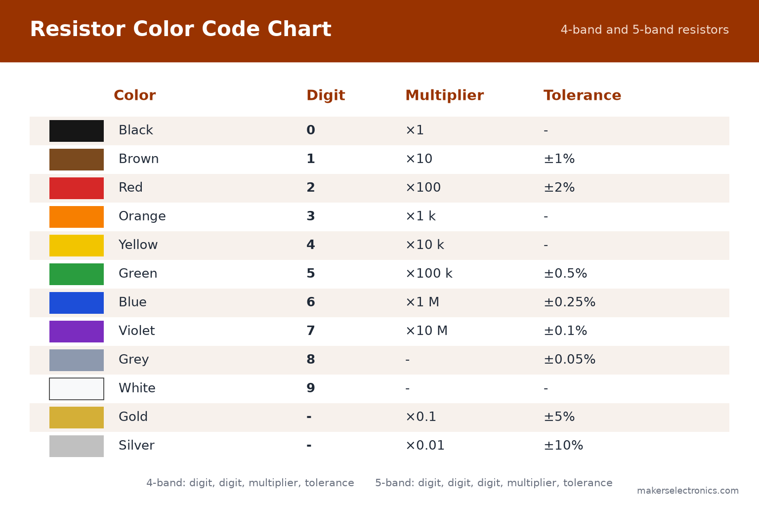
| Color | Digit | Multiplier | Tolerance |
|---|---|---|---|
| Black | 0 | ×1 | – |
| Brown | 1 | ×10 | ±1% |
| Red | 2 | ×100 | ±2% |
| Orange | 3 | ×1 kΩ | – |
| Yellow | 4 | ×10 kΩ | – |
| Green | 5 | ×100 kΩ | ±0.5% |
| Blue | 6 | ×1 MΩ | ±0.25% |
| Violet | 7 | ×10 MΩ | ±0.1% |
| Grey | 8 | – | ±0.05% |
| White | 9 | – | – |
| Gold | – | ×0.1 | ±5% |
| Silver | – | ×0.01 | ±10% |
Reading the bands in three steps
- Turn the resistor so the tolerance band is on the right. It is usually gold or silver and sits slightly apart from the other bands.
- Write down the digits of the first two bands (four-band) or three bands (five-band).
- Multiply by the multiplier band, then note the tolerance.
Common values at a glance
| Value | Four-band colors |
|---|---|
| 220 Ω | red, red, brown, gold |
| 330 Ω | orange, orange, brown, gold |
| 1 kΩ | brown, black, red, gold |
| 4.7 kΩ | yellow, violet, red, gold |
| 10 kΩ | brown, black, orange, gold |
| 100 kΩ | brown, black, yellow, gold |
Some resistors have a sixth band for the temperature coefficient. You can ignore it for hobby work. Brown, red and orange are easy to confuse on old or faded resistors. If you are not sure, measure the resistor with a multimeter instead of guessing (see section 12).
5. How to Read SMD Resistor Codes
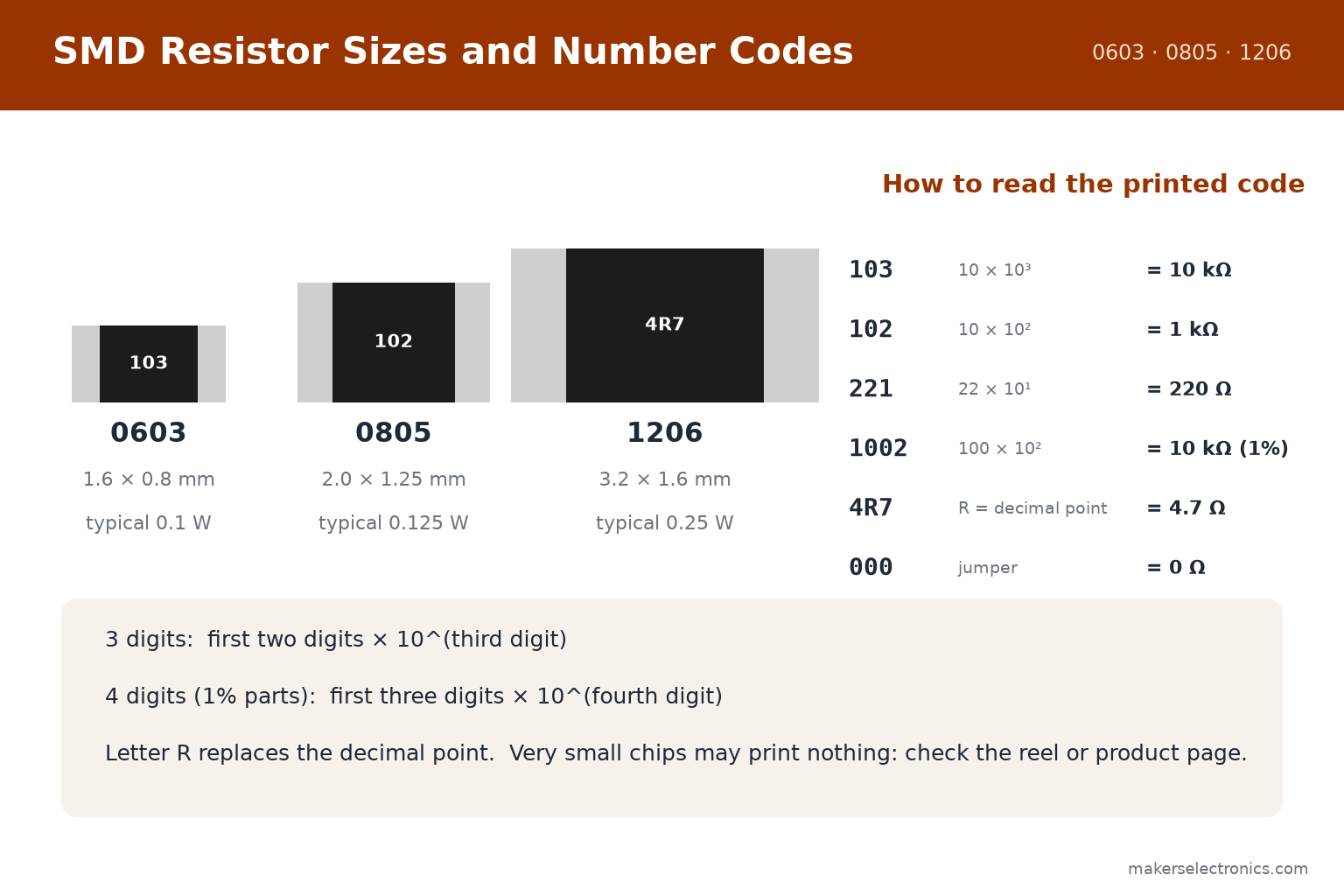
SMD (surface-mount) resistors are small rectangular chips. Instead of colors they carry a printed number code. The size is named by a four-digit code. These are the common ones:
| Size name | Metric name | Dimensions | Typical power |
|---|---|---|---|
| 0603 | 1608 | 1.6 × 0.8 mm | 0.1 W |
| 0805 | 2012 | 2.0 × 1.25 mm | 0.125 W |
| 1206 | 3216 | 3.2 × 1.6 mm | 0.25 W |
Always confirm the exact rating on the product page or the datasheet, because it depends on the manufacturer.
How to decode the printed code:
- Three digits: the first two digits are the value and the third is the multiplier (the number of zeros). 103 = 10 followed by three zeros = 10,000 Ω = 10 kΩ.
- Four digits (common on 1% parts): the first three digits are the value and the fourth is the multiplier. 1002 = 100 followed by two zeros = 10 kΩ.
- The letter R marks the decimal point: 4R7 = 4.7 Ω and R22 = 0.22 Ω.
- 000 or 0 is a 0 Ω resistor, used as a jumper on a PCB.
- Small 1% parts sometimes use the EIA-96 code: two digits and a letter. For example 01C = 100 × 100 = 10 kΩ. Look up the code in the EIA-96 table.
| Printed code | Value | How |
|---|---|---|
| 101 | 100 Ω | 10 × 10¹ |
| 102 | 1 kΩ | 10 × 10² |
| 103 | 10 kΩ | 10 × 10³ |
| 104 | 100 kΩ | 10 × 10⁴ |
| 221 | 220 Ω | 22 × 10¹ |
| 472 | 4.7 kΩ | 47 × 10² |
| 1002 | 10 kΩ | 100 × 10² |
| 4R7 | 4.7 Ω | R is the decimal point |
0805 and 1206 are the easiest sizes to hand-solder with a soldering station. 0603 saves space but needs a fine tip and steady hands. Browse 0603, 0805 and 1206 resistors. Keep SMD resistors in their labeled bags: the smallest sizes are often unmarked, so you cannot identify them by eye.
6. Standard Values and Tolerance
Resistors are not made in every value. Manufacturers follow the E series. E12 (±10%) has 12 values per decade: 10, 12, 15, 18, 22, 27, 33, 39, 47, 56, 68, 82. E24 (±5%) has 24 values per decade and E96 (±1%) has 96. That is why 220 Ω, 330 Ω and 470 Ω exist, but 250 Ω does not. See the E series of preferred numbers.
Tolerance is how far the real resistance can be from the marked value. A 10 kΩ ±5% resistor can measure anywhere from 9.5 kΩ to 10.5 kΩ and still be within specification. That does not matter for an LED, but it can matter for a voltage divider feeding an ADC.
When your calculation gives a value that is not standard, use the nearest standard value. Go up, not down, when the resistor protects something, such as an LED.
7. Power Rating (Wattage)
A resistor turns the power it dissipates into heat. Calculate it with P = I² × R or P = V² ÷ R, and choose a resistor whose rating is higher than the result. Common ratings are 0.125 W, 0.25 W, 0.5 W and 1 W, then larger power resistors. A safe rule is to choose a rating of at least twice the calculated power so the part runs warm, not hot.
Example: a 100 Ω resistor across 12 V carries I = 12 ÷ 100 = 0.12 A and dissipates P = 12² ÷ 100 = 1.44 W. A 0.25 W resistor would overheat and burn. Use a 3 W or higher part from the power resistors range, and mount it with air space around it, away from plastic parts and wires.
A resistor that is too hot to touch is a warning. Check the power calculation before you power the circuit again.
8. Choosing a Resistor for an LED
An LED has almost no resistance once it conducts. Without a resistor in series, it draws as much current as the supply allows and burns out. The formula is:
R = (Vs − Vf) ÷ I
Vs is the supply voltage, Vf is the LED forward voltage and I is the current you want. Typical forward voltages are about 1.8 to 2.2 V for red, 2.0 to 2.2 V for yellow and orange, 2.0 to 3.2 V for green (it varies a lot), and 2.8 to 3.4 V for blue and white. Check the datasheet for your LED.
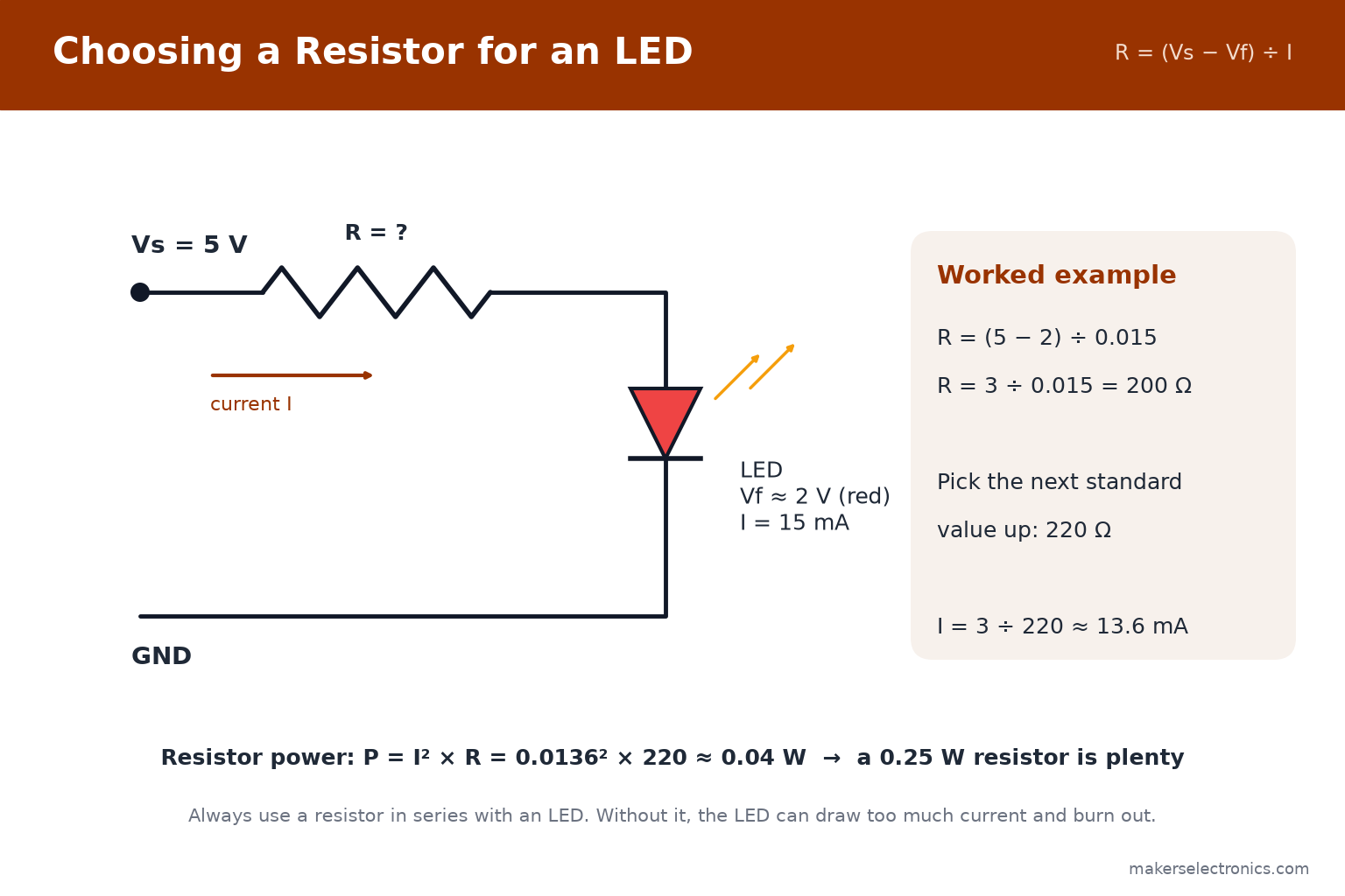
- Choose the current. 5 to 15 mA is bright enough for most indicator LEDs. A standard 5 mm LED is usually rated for 20 mA at most.
- Calculate R = (Vs − Vf) ÷ I.
- Round up to the next standard value.
- Check the power: P = I² × R. For LEDs it is a few milliwatts, so a 0.25 W resistor is plenty.
| Supply | LED | Target current | Calculated R | Use |
|---|---|---|---|---|
| 5 V | Red (Vf 2.0 V) | 10 mA | 300 Ω | 330 Ω |
| 5 V | Red (Vf 2.0 V) | 15 mA | 200 Ω | 220 Ω |
| 5 V | White (Vf 3.2 V) | 10 mA | 180 Ω | 180 Ω |
| 3.3 V | Red (Vf 2.0 V) | 10 mA | 130 Ω | 150 Ω |
Two notes. First, if the supply is only slightly above the LED voltage (for example a white LED on 3.3 V), the current becomes very sensitive to small voltage changes. Use a higher supply voltage or a constant-current driver. Second, an Arduino Uno pin should supply about 20 mA at most (40 mA is the absolute maximum), so the resistor protects the pin as well as the LED. Use one resistor per LED, and do not share one resistor between several LEDs. Browse our LEDs. Addressable LEDs such as the WS2812 contain their own driver chip: see our WS2812 guide.
9. Pull-up and Pull-down Resistors
A digital input that is not connected to anything is said to float. It picks up noise and reads random HIGH and LOW values. A pull-up resistor connects the pin to the supply, so it reads HIGH by default. When the button is pressed, the pin is connected to ground and reads LOW. A pull-down resistor does the opposite.
The usual value is 4.7 kΩ to 10 kΩ. It is low enough to hold the pin firmly, and high enough not to waste current: with a 10 kΩ pull-up on 5 V, a pressed button draws only 0.5 mA.
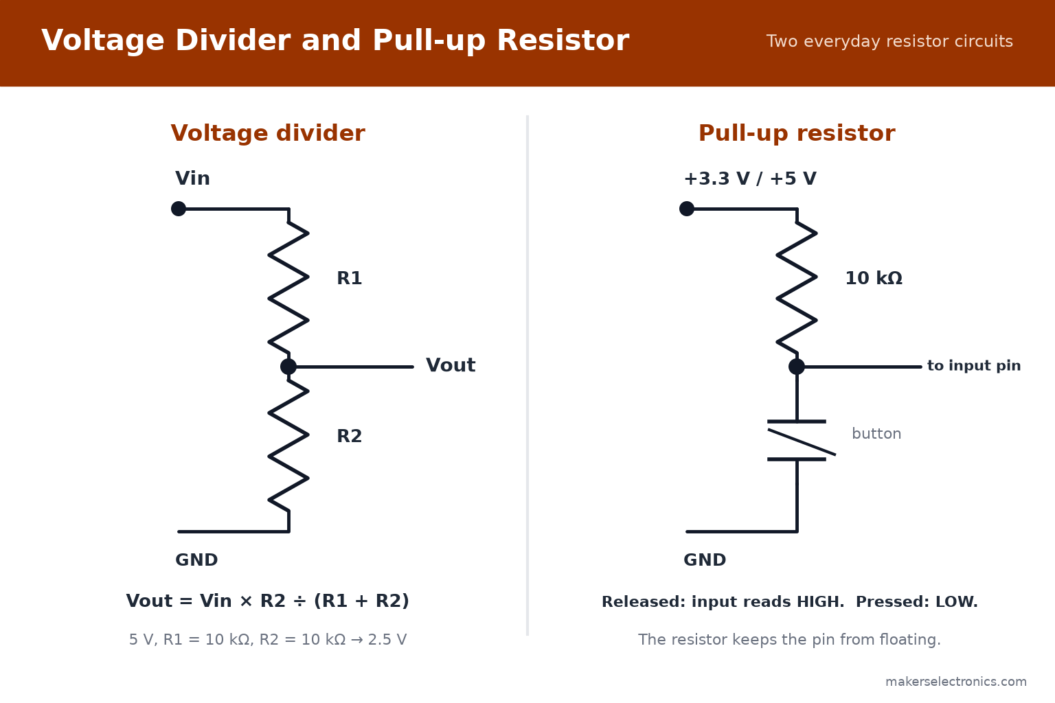
Most Arduino boards have internal pull-up resistors, so you often do not need an external one. The internal pull-up of the ATmega328P (Arduino Uno) is roughly 20 to 50 kΩ. See the official Arduino digital input pull-up tutorial.
const int buttonPin = 2;

void setup() {
  Serial.begin(9600);
  pinMode(buttonPin, INPUT_PULLUP);   // uses the internal pull-up resistor
}

void loop() {
  if (digitalRead(buttonPin) == LOW) {   // LOW means the button is pressed
    Serial.println("Button pressed");
    delay(200);                          // simple debounce
  }
}
If you use an external 10 kΩ pull-up instead, change the pin mode to INPUT. I2C buses also need pull-up resistors, commonly 4.7 kΩ, and many modules already include them. See I2C vs SPI vs UART.
10. Voltage Divider
Two resistors in series divide a voltage. The output is taken from the point between them:
Vout = Vin × R2 ÷ (R1 + R2)
| Vin | R1 | R2 | Vout |
|---|---|---|---|
| 5 V | 10 kΩ | 10 kΩ | 2.5 V |
| 5 V | 1 kΩ | 2 kΩ | 3.33 V |
| 5 V | 2 kΩ | 1 kΩ | 1.67 V |
Dividers are used to read a sensor with an ADC (for example a thermistor or a light-dependent resistor), to scale a voltage down for a measurement input, and to bring a slow 5 V signal down to a 3.3 V input. Fast signals need a proper level shifter instead.
A divider only works for signals. Its output voltage drops when something draws current from it, so never use one to power a motor, a module or an LED. For that, use a regulator: see Buck Converter vs LDO Regulator.
11. Resistors in Series and in Parallel
- In series, resistances add: R = R1 + R2. Two 220 Ω resistors in series give 440 Ω.
- In parallel, R = (R1 × R2) ÷ (R1 + R2). The total is always smaller than the smallest resistor. Two equal resistors in parallel give half the value: two 10 kΩ resistors give 5 kΩ.
Combining resistors is a quick way to make a value you do not have in the drawer. Power is shared too: two equal 0.25 W resistors in parallel can handle about 0.5 W together.
12. How to Measure a Resistor with a Multimeter
- Switch the circuit off and discharge any capacitors.
- Remove the resistor from the circuit, or at least lift one leg. Other parts in parallel will make the reading lower than the real value.
- Set the multimeter to the ohm (Ω) range. An auto-range meter selects the range for you.
- Touch the probes to the two legs. Do not hold both metal tips with your fingers, because your body adds a parallel resistance.
- Compare the reading with the color code or SMD code. It should be within the tolerance. OL means open circuit or a value above the range.
For SMD parts, use fine probes or tweezer probes. Browse UNI-T multimeters and test equipment or the multimeter category.
13. Common Mistakes to Avoid
- Connecting an LED without a series resistor.
- Using a 0.25 W resistor where the calculated power is higher than 0.125 W. Always leave a safety margin.
- Reading the color bands from the wrong end. Start from the end opposite the tolerance band.
- Mixing up 1 kΩ (brown, black, red) and 10 kΩ (brown, black, orange).
- Reading the SMD code 103 as 103 Ω. It is 10 kΩ.
- Measuring a resistor while it is still soldered into a powered circuit.
- Using ±5% resistors in a divider or filter that needs accuracy.
- Touching a power resistor after the circuit has been running.
14. Starter Values to Keep in Your Kit
If you build with Arduino, ESP32 and general electronics, these values cover most jobs:
| Value | Typical use | Colors (four-band) |
|---|---|---|
| 220 Ω | LEDs on 5 V | red, red, brown, gold |
| 330 Ω | LEDs on 5 V, lower brightness | orange, orange, brown, gold |
| 1 kΩ | Transistor base, light-load LEDs, general use | brown, black, red, gold |
| 4.7 kΩ | I2C pull-ups, general use | yellow, violet, red, gold |
| 10 kΩ | Pull-up and pull-down, dividers | brown, black, orange, gold |
| 100 kΩ | High-impedance dividers, bleed resistors | brown, black, yellow, gold |
Browse through-hole resistors for breadboard work and SMD resistors for PCB designs. For transistor base resistors, see our transistors guide. Current prices and availability are shown on each product page.
15. Frequently Asked Questions
Which end do I start reading the color bands from?
Start from the end opposite the tolerance band. The tolerance band is usually gold or silver and is set slightly apart from the others.
What does 103 mean on an SMD resistor?
It is 10 followed by three zeros, which is 10,000 Ω or 10 kΩ.
Does the direction of a resistor matter?
No. A resistor has no polarity and works the same in either direction.
Can I use a resistor with a higher power rating than needed?
Yes. A higher wattage rating is safe. The part is just physically larger.
What resistor should I use with an LED on an Arduino (5 V)?
For a typical red or green LED, 220 Ω to 330 Ω gives a safe current of roughly 9 to 14 mA. For other colors, calculate it with R = (Vs − Vf) ÷ I.
What is the difference between a 1% and a 5% resistor?
Tolerance. A 1% resistor stays much closer to its marked value, which matters in dividers, filters and measurement circuits. For LEDs and pull-ups, 5% is fine.
What is a 0 Ω resistor for?
It is a jumper in a resistor package. It bridges two tracks on a PCB or lets a design be configured during assembly.
Why does my multimeter reading differ from the color code?
The resistor may be within its tolerance, still connected to the circuit, or the reading may be affected by your fingers on the probes. Measure it out of circuit.
16. Conclusion
Reading a resistor comes down to a few habits: find the tolerance band, read the digits, apply the multiplier, and check the result with a multimeter when in doubt. For SMD parts, decode the printed number: the last digit is the number of zeros. Choose a standard value, make sure the power rating has a safety margin, and always put a resistor in series with an LED.
When you are ready to build, browse the through-hole resistors, SMD resistors, power resistors and potentiometers at Makers Electronics.



Leave a comment
You must be logged in to post a comment.