



1. Introduction
Every project needs a way to connect wires to a board: a motor, a battery, a sensor, a power supply. Soldering wires directly works, but it makes a board hard to repair and hard to test. Terminal blocks and JST connectors solve this: they make a connection that is solid, removable and repeatable.
This guide explains the types of terminal blocks (screw, pluggable and barrier), what pitch means and why 5.0 mm is not 5.08 mm, how to read part names such as KF127-5.0-3P, how to pick a wire size for the current, how to wire a screw terminal correctly, how JST XH and PH connectors differ, and how to choose between them. Every section has worked numbers and details you can check against the product page.

KF127-5.0-3P Green Terminal Block 300V/10A 3 Pins 5mm Pitch

Pluggable Terminal Block KF2EDGR-5.08-4P PCB Solder Right Angle 5.08mm 4 Pin

HB9500SS Barrier Terminal Block with Cover 300V 30A 2 Pin 9.5mm Pitch
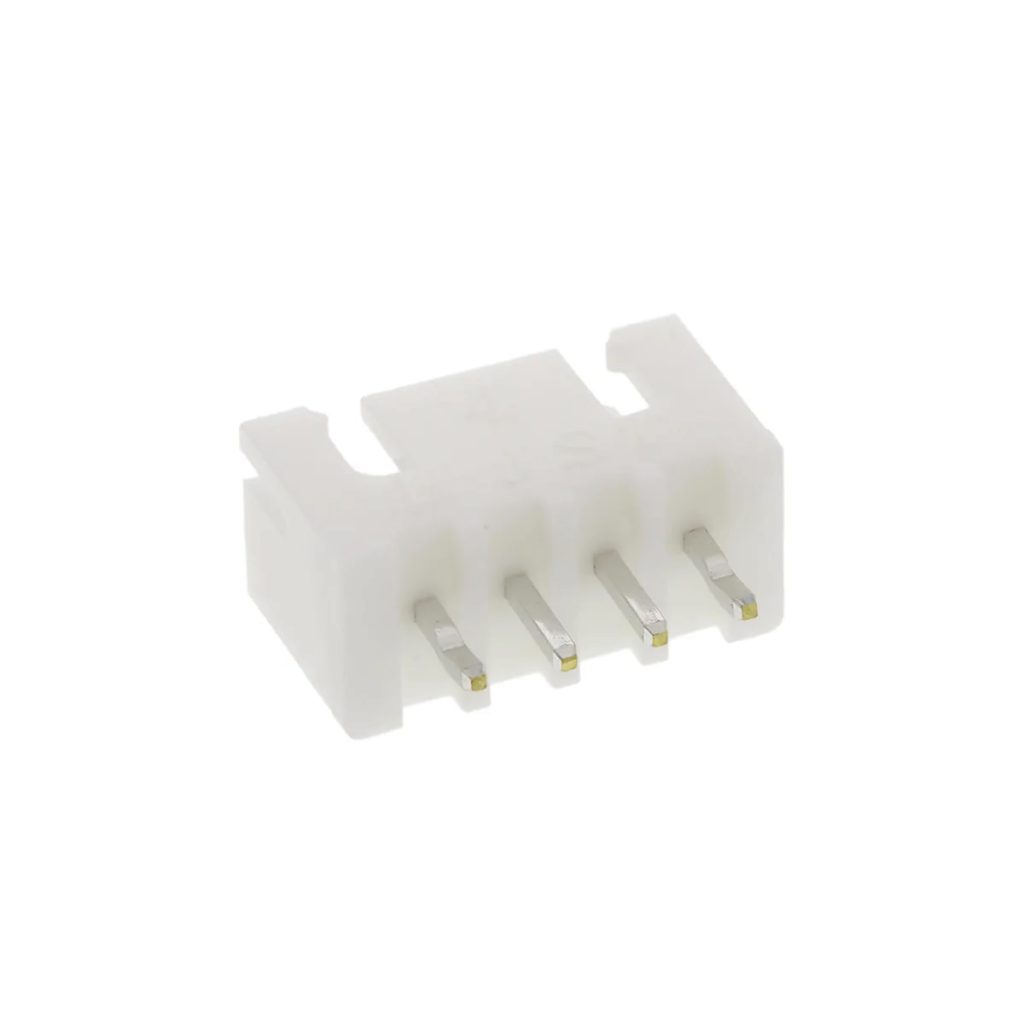
B4B-XH-A JST XH Data Terminal Male 4 Pin Connector Header 2.5mm

JST XH Female To Female Data Cable 4 Pin 2.54mm 30cm

PHR-4 JST PH Connector Housing Female 4 Pin 2mm with 20cm Terminal Cable
2. Types of Terminal Blocks
A terminal block is a connector that clamps a bare wire with a screw, so you can connect and disconnect wires without soldering the wire itself. The block is soldered to the board. There are three families you will meet:
| Type | How it works | Typical use | Browse |
|---|---|---|---|
| Fixed screw terminal block (KF127, KF126, KF128) | A block soldered to the board. The wire clamps under a screw. | Power inputs, motor and relay outputs, general wiring | Terminal blocks |
| Pluggable terminal block (KF2EDG series) | A header soldered to the board and a plug the wire screws into. The plug pulls out. | Boards you often remove or service, modular designs | Terminal blocks |
| Barrier terminal block (HB9500SS) | A large block with barriers between poles, usually with a cover. | High current and higher voltage, mains and power wiring | Terminal blocks |
| Spring lever connector (WAGO) | A lever clamps the wire, no screw and no board needed. | Joining wires in boxes and lighting | WAGO connectors |

KF127-5.0-2P Green Terminal Block 300V/10A 2 Pins 5mm Pitch

KF126-5.0-2P Green Terminal Block 300V 10A 2 Pin

KF128-5.0-3P Terminal Block 3 Pin 300V 10A 5mm Pitch

Pluggable Terminal Block KF2EDGR-5.08-2P Right Angle PCB Solder 5.08mm 2 Pin

Pluggable Terminal Block KF2EDGV-5.08-2P PCB Solder Straight 5.08mm 2 Pin

Pluggable Terminal Block 2 Pin Pitch 3.81mm
HB9500SS Barrier Terminal Block with Cover 300V 30A 2 Pin 9.5mm Pitch

Terminal Block 2 Pin KF128-7.5-2P 7.5mm
3. What Is Pitch?
Pitch is the distance between the centers of two neighboring pins. It decides whether a connector fits the holes of a board, and which blocks can sit side by side. Pitch is the first thing to check, before the number of pins, the current or the color.
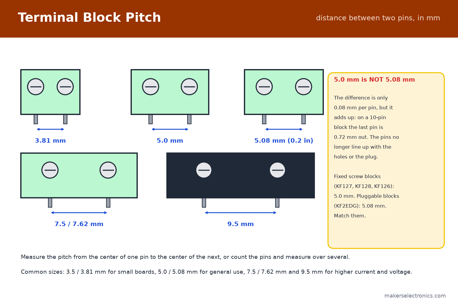
| Pitch | Typical use | Examples in our range |
|---|---|---|
| 3.5 / 3.81 mm | Small boards, low current | Pluggable KF2EDGR-3.81, pluggable 3.81 mm |
| 5.0 mm | General use, up to about 10 A | KF127-5.0, KF128-5.0, KF126-5.0 |
| 5.08 mm (0.2 in) | General use, pluggable blocks | KF2EDGR-5.08, KF2EDGV-5.08 |
| 7.5 / 7.62 mm | More current and voltage | KF128-7.5 |
| 9.5 mm | High current, barrier blocks | HB9500SS |
5.0 mm and 5.08 mm look the same but are not. The 5.08 mm pitch is exactly 0.2 inch, from the imperial grid, and 5.0 mm is metric. The difference is 0.08 mm per pin, which does not matter for two pins but adds up: on a 10-pin block the last pin is 0.72 mm off, and the pins no longer line up with the holes. Check the exact pitch on the product page, and match a pluggable header with its plug.
4. Reading Part Names: KF127-5.0-3P
Terminal block names follow a pattern. For example KF127-5.0-3P:
- KF127: the series. KF126, KF127 and KF128 are fixed screw blocks with different housing shapes. They differ in housing shape, for example in height and in how blocks interlock.
- 5.0: the pitch in millimeters.
- 3P: three poles (pins).
- KF2EDGR-5.08-2P: a pluggable header and plug in the KF2EDG series. The R means right angle (the plug enters from the side), and the V in KF2EDGV means straight (vertical).
Our listings also give the rating, for example 300 V / 10 A for the KF127 and 8 A for the KF126, and the number of pins. Always check the rating of the exact part, because it depends on the series and the pitch. Most terminal blocks are green (the common color), and the housing is normally flame-retardant.
KF127-5.0-2P Green Terminal Block 300V/10A 2 Pins 5mm Pitch
KF127-5.0-3P Green Terminal Block 300V/10A 3 Pins 5mm Pitch

Terminal Block 3 Pins KF126-5.0-3P 8A 300V Green
KF128-5.0-3P Terminal Block 3 Pin 300V 10A 5mm Pitch

Terminal Block 3Pin 3.96mm Pitch
5. Pluggable Terminal Blocks
A pluggable block has two parts: a header soldered to the board and a plug that the wires screw into. You can remove the plug with all its wires attached, which makes boards easy to service, replace and test.
- Right angle (KF2EDGR): the plug enters from the side of the board, so the wires run parallel to it. Good for boards inside enclosures.
- Straight (KF2EDGV): the plug enters from above.
- Pins: available from 2 to 12 poles and more. A longer block can be built by joining plugs.
- Match the pair: a plug fits only a header of the same series and pitch, for example 5.08 mm with 5.08 mm.
The listings show right-angle KF2EDGR-5.08 blocks from 2 to 12 pins, straight KF2EDGV-5.08 blocks, and smaller 3.81 mm versions for compact boards. For a motor driver, an Arduino shield or any board you will take out for adjustments, pluggable blocks save time.
Pluggable Terminal Block KF2EDGR-5.08-2P Right Angle PCB Solder 5.08mm 2 Pin
Pluggable Terminal Block KF2EDGR-5.08-4P PCB Solder Right Angle 5.08mm 4 Pin

Pluggable Terminal Block KF2EDGR-5.08-6P PCB Solder Right Angle 5.08mm 6 Pin
Pluggable Terminal Block KF2EDGV-5.08-2P PCB Solder Straight 5.08mm 2 Pin

Pluggable Terminal Block KF2EDGV-5.08-3P PCB Solder Striate 5.08mm 3 Pin

Pluggable Terminal Block KF2EDGR-3.81-3P PCB Solder Right Angle 3.81mm 3 Pin
6. Barrier Terminal Blocks
Barrier blocks, such as the HB9500SS series, are large blocks with a 9.5 mm pitch and a protective cover. The listings show 300 V / 30 A for the 2-pin and 3-pin versions. They are made for thick wire and higher current: power supplies, inverters, battery banks and machine wiring.
- Use ring or fork lugs on the wire ends for thick conductors, crimped, not soldered.
- Use the cover to prevent accidental contact, especially with mains voltage.
- Only work on mains wiring if you are trained to. See the safety note in the soldering guide, and use the right wire size for the current.
For general low-voltage boards, a barrier block is oversized. Choose it when the current is above what a 5.0 mm block can carry, or when the wire is too thick to fit.
HB9500SS Barrier Terminal Block with Cover 300V 30A 2 Pin 9.5mm Pitch

HB9500SS Barrier Terminal Block with Cover 300V/30A 3 Pin 9.5mm Pitch
7. Choosing the Wire Size
The wire must carry the current without getting warm, and it must fit the terminal. These are typical limits for short runs of chassis wiring. They are not guarantees, because the safe current depends on the insulation, the temperature, the bundle and the length:
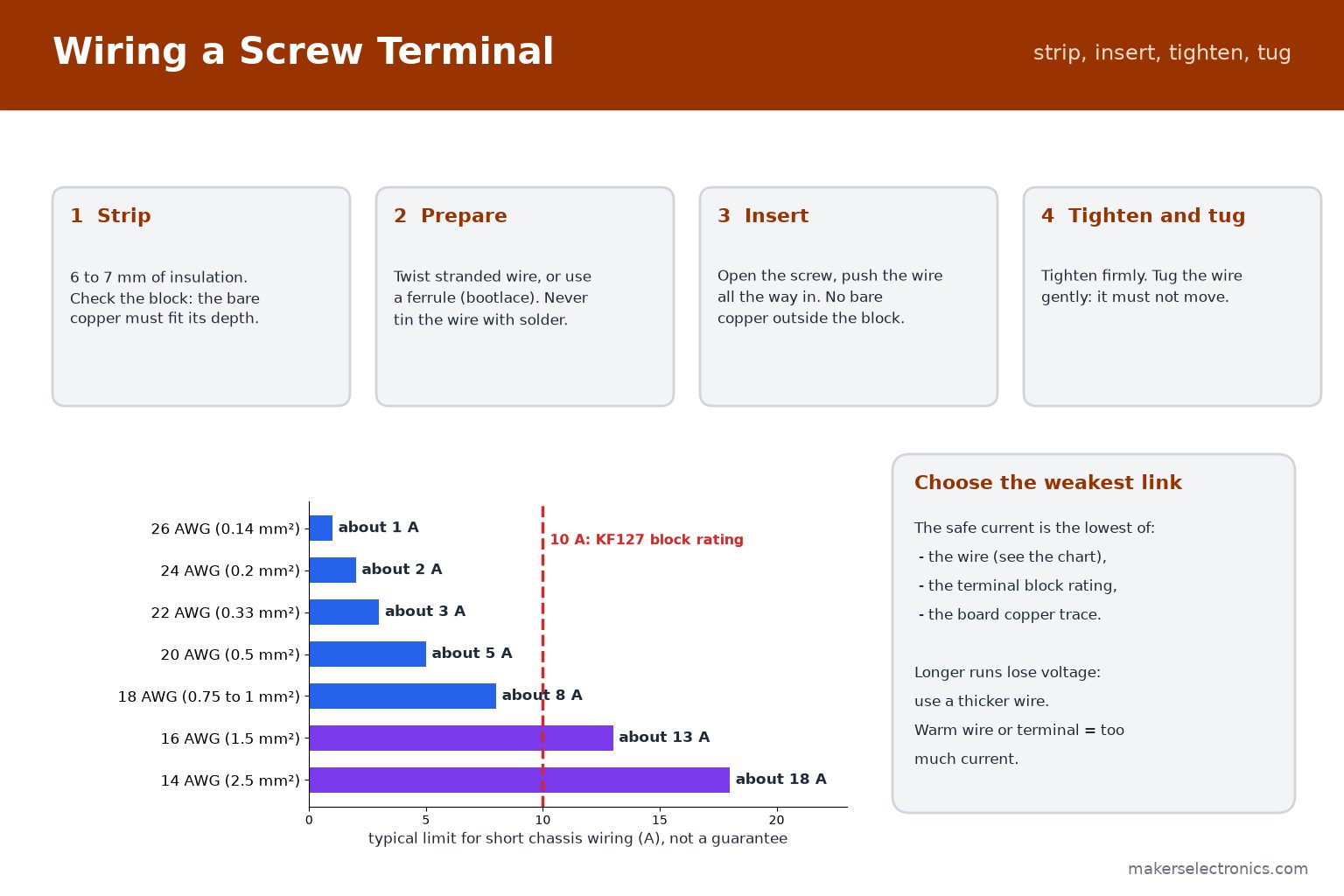
| Wire size | Cross-section | Typical limit |
|---|---|---|
| 24 AWG | 0.2 mm² | about 2 A |
| 22 AWG | 0.33 mm² | about 3 A |
| 20 AWG | 0.5 mm² | about 5 A |
| 18 AWG | 0.75 to 1 mm² | about 8 A |
| 16 AWG | 1.5 mm² | about 13 A |
| 14 AWG | 2.5 mm² | about 18 A |
- The weakest link decides. A KF127 block is rated 10 A, so a 14 AWG wire does not make it carry more. The block, the wire and the board trace are three limits: use the lowest.
- Longer runs lose voltage. For a 12 V motor at 5 A over several meters, use a thicker wire than the table suggests.
- Warmth is a warning. If a wire or a terminal gets warm, the current is too high or the connection is loose.
Stranded, flexible wire is best for moving parts. Solid wire suits fixed wiring. See our wires category for different sizes and colors.
8. How to Wire a Screw Terminal Correctly
- Strip 6 to 7 mm of insulation (check the depth of the block). Too short and the clamp grips the insulation, and too long leaves bare copper showing.
- Prepare the strands. Twist stranded wire tightly, or crimp a ferrule (bootlace) on it, which gives the cleanest, most reliable connection. Do not tin the wire end with solder: solder cold-flows under the screw pressure and the joint loosens.
- Open the screw and push the wire all the way into the opening. No bare copper should be outside the block.
- Tighten firmly, then tug the wire gently. It must not move.
- Check again after the first hours of use for loads with high current or vibration, and tighten if needed.
For a fixed block, solder the pins to the board with a clean joint, and keep the block flat against the board. Use a soldering station with a suitable tip; larger pins need more heat. See our soldering guide for beginners.
9. JST Connectors: XH and PH
JST connectors are small plastic connectors with a polarized housing, so they plug in only one way. They are used for batteries, sensors, fans, LED strips and boards. The two series you will meet most are XH and PH:
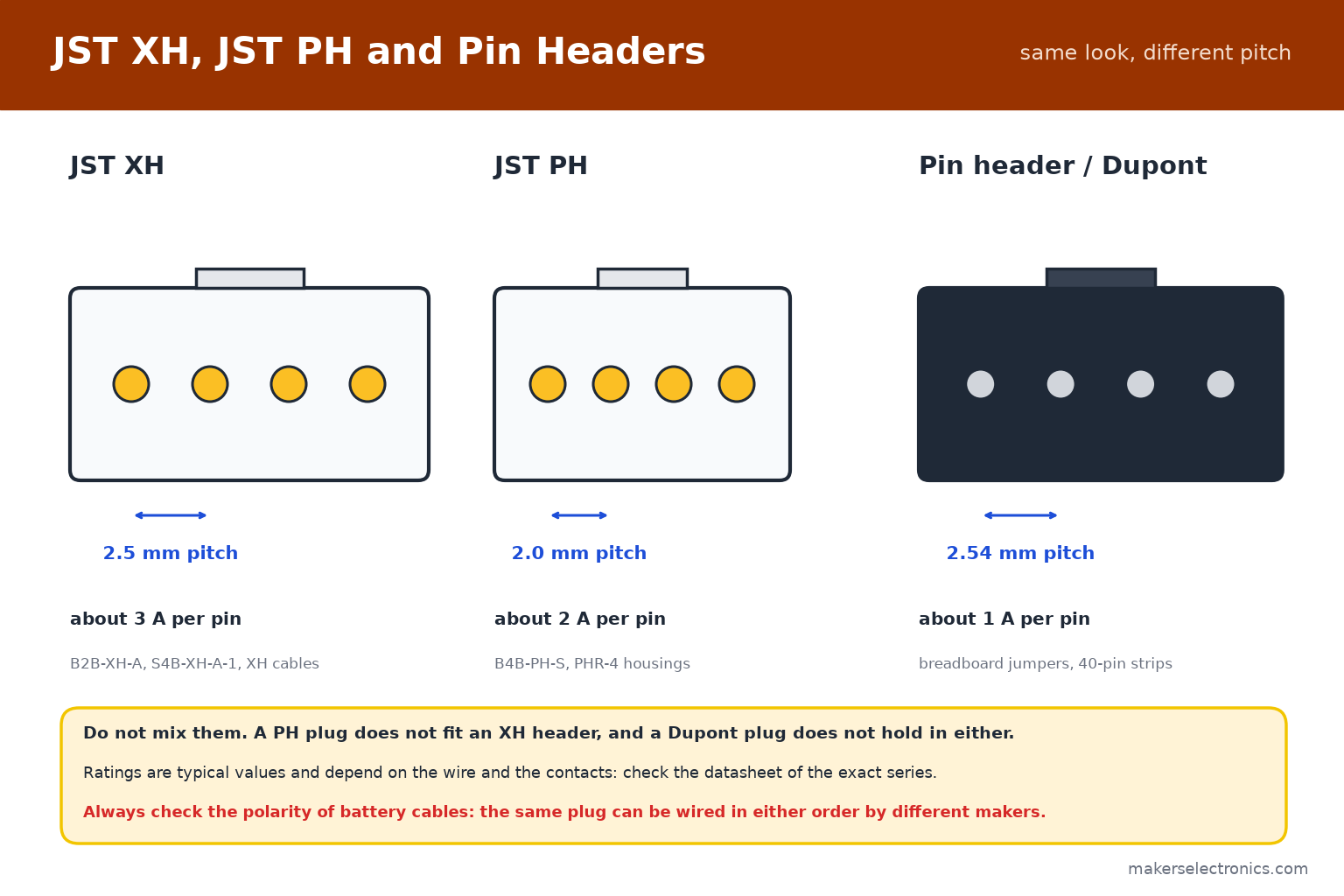
| Series | Pitch | Typical rating | Typical use |
|---|---|---|---|
| JST XH | 2.5 mm | about 3 A per pin | Battery balance leads, motors, LED strips, sensor boards |
| JST PH | 2.0 mm | about 2 A per pin | Small batteries, compact boards |
| Pin header (Dupont) | 2.54 mm | about 1 A per pin | Breadboards, jumper wires, modules |
The ratings above are typical and depend on the wire and the contacts: check the datasheet of the exact series.
- JST XH has a 2.5 mm pitch and a robust latch. Listings for XH cables sometimes state 2.54 mm. The cables are made for XH headers, which are 2.5 mm.
- JST PH has a 2.0 mm pitch and is smaller. PHR is the housing (the plug) and B…PH is the header on the board.
- Do not mix them. A PH plug does not fit an XH header, and a pin-header plug does not fit either.

B2B-XH-A JST XH Data Terminal Male 2 Pin Connector Header 2.5mm

B3B-XH-A JST XH Data Terminal Male 3 Pin Connector Header 2.5mm
B4B-XH-A JST XH Data Terminal Male 4 Pin Connector Header 2.5mm
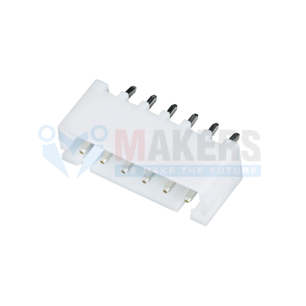
B6B-XH-A JST XH Data Terminal Male 6 Pin Connector Header 2.5mm

B8B-XH-A JST XH Data Terminal Male 8 Pin Connector Header 2.5mm

S2B-XH-A-1 JST XH Data Terminal Angle Male 2 Pin Connector Header 2.5mm

S4B-XH-A-1 JST XH Data Terminal Angle Male 4 Pin Connector Header 2.5mm

B3B-PH-S JST PH Data Terminal Male 3 Pin Connector Header 2mm
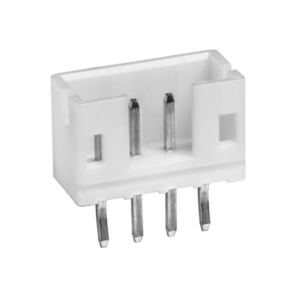
B4B-PH-S JST PH Data Terminal Male 4 Pin Connector Header 2mm
10. Reading JST Part Names
JST names follow a pattern too. For example, B4B-XH-A and S4B-XH-A-1:
- B…: a straight (top-entry) header, where the plug comes from above. S…: a side-entry (right-angle) header, where the plug comes in parallel to the board.
- The number: the number of pins. XH headers are listed from 2 up to 8 pins in our range.
- XH or PH: the series, which sets the pitch.
- PHR-4: a PH housing (plug) with 4 positions. XH housings use similar XHP names.
The listings in our shop describe each part in plain words, such as ‘JST XH Data Terminal Male 4 Pin Connector Header 2.5mm’ or ‘JST PH Connector Housing Female 4 Pin 2mm with 20cm Terminal Cable’. Always match series, number of pins and entry direction.
11. JST Cables and Crimping
For most hobby projects, the easiest way is to use ready-made cables: a plug with wires already crimped. Our range includes XH female-to-female cables from 2 to 8 pins, 30 cm long, and cables with a JST plug on one end and bare wire on the other, which you can solder or screw into a terminal block.

JST XH Female To Female Data Cable 2 Pin 2.54mm 30cm

JST XH Female To Female Data Cable 3 Pin 2.54mm 30cm
JST XH Female To Female Data Cable 4 Pin 2.54mm 30cm

JST XH Female To Female Data Cable 6 Pin 2.54mm 30cm

Data Cable JST 2 Pin 2.54mm 26AWG 15cm One Side Terminal

Data Cable JST 3 Pin 2.54mm 26AWG 25cm One Side Terminal

PHR-2 JST PH Connector Housing Female 2 Pin 2mm with 20cm Terminal Cable
PHR-4 JST PH Connector Housing Female 4 Pin 2mm with 20cm Terminal Cable
- To make your own, you need the housing, the crimp contacts of the same series and a crimping tool made for them. A general crimping tool for other terminals will not hold these small contacts.
- Wire size: use 22 to 28 AWG for small JST contacts. The contacts are made for thin wire.
- Strain relief: do not pull a cable by the wire. Pull on the housing, and keep the wire from bending at the plug.
- Soldering a bare end: tin and solder with a clean tip, and cover the joint with heat-shrink tubing.
See our JST cable, JST connector and crimp connector categories.
12. Polarity: Check Before You Connect
JST housings are keyed, so a plug goes in one way, but that does not make the wiring correct. The same-looking plug can be wired in either order by different makers. This matters most for batteries: a battery with a JST plug wired with reversed polarity can destroy a board in a second.
- Check the red and black wires against the + and − marks on the board before connecting a battery.
- Do not trust the plug shape alone. When you buy a new battery for an existing board, check with a multimeter first: see our multimeter guide.
- If the order is wrong, swap the two pins in the housing with a small tool, or buy the matching cable.
- Mark the cables with colored heat shrink or a label, so a mix-up cannot happen later.
13. Pin Headers and Dupont Connectors
The 2.54 mm pin header is the standard of breadboards, Arduino and many modules. It is not a terminal block and not a JST connector, but it is everywhere. Male headers come in strips of 40 that you break to length, in straight and right-angle versions, and in 2.54 mm round female strips for sockets.

Pin Headers Male 2.54mm : 5Pin, Straight, Black, 11mm

Pin Headers Male 2.54mm : 40-Pin, Straight, Black, 11mm

Pin Headers Male 2.54mm : 40-Pin, Right Angle, Black
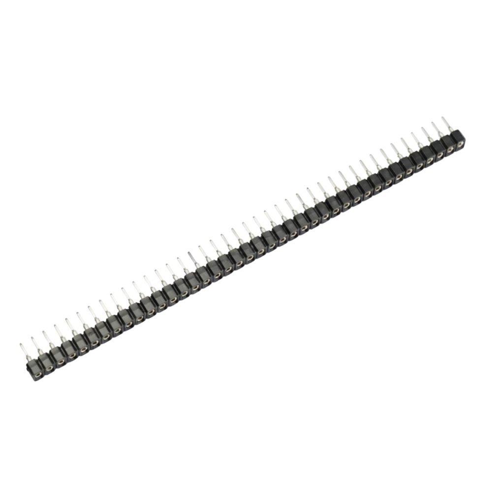
Round Pin Headers Female 2.54mm : 40-Pin, Straight, Black, 7.5mm
Dupont jumper wires fit these headers. Their ratings are small (around 1 A per pin), so they are for signals and low-power modules. See our jumper wires and breadboards guide and the pin header category. For power and motors, use terminal blocks or larger connectors.
14. Choosing a Connector
| Job | Best choice | Why |
|---|---|---|
| Power input of a board (12 V, a few amps) | KF127 or pluggable KF2EDG | Solid screw connection for thicker wire |
| A board you will remove often | Pluggable KF2EDG | The plug pulls out with the wires attached |
| High current (up to 30 A) or thick wire | Barrier block (HB9500SS) | Large clamps, cover, 9.5 mm pitch |
| Battery with a small plug | JST XH or PH (matching the battery) | Polarized, small, repeatable |
| Sensor, fan or LED strip cable | JST XH with a ready-made cable | Easy to plug and unplug, keyed |
| Breadboard, modules, signals | 2.54 mm pin header and Dupont wire | Standard for prototyping |
| Joining two wires in a box | WAGO lever connector | No tools, no board |
| DC adapter with a barrel plug | DC jack adapter with terminal block | Converts the plug to screw terminals |

Female DC Jack Adapter with Terminal Block
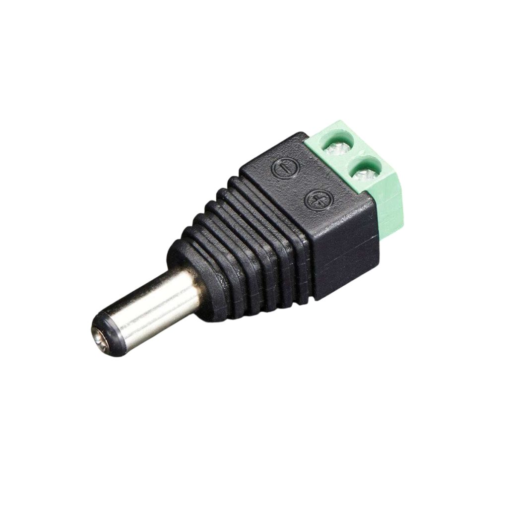
Male DC Jack Adapter with Terminal Block
Browse all connectors and terminals, including power connectors. Prices and availability are on each product page.
15. Common Mistakes to Avoid
- Mixing 5.0 mm and 5.08 mm blocks, or ordering a header without matching its plug.
- Putting a wire under the screw with the insulation in the clamp.
- Tinning a stranded wire with solder before a screw terminal.
- Using a wire that is too thin for the current, or a block that is rated lower than the load.
- Pulling a JST cable by the wire instead of the housing.
- Connecting a battery before checking the polarity of its JST plug.
- Using a general crimping tool on JST contacts.
- Mixing JST XH, PH and Dupont plugs.
- Leaving mains terminals uncovered.
16. Connectors to Keep in Your Kit
For Arduino, ESP32 and general electronics, this set covers most needs:
| Part | Why |
|---|---|
| KF127-5.0 blocks, 2 and 3 pins | Power and motor connections on boards |
| Pluggable KF2EDGR-5.08, 2 to 6 pins | Boards you remove often |
| JST XH headers and cables, 2 to 6 pins | Sensors, fans and LED strips |
| JST PH housing with cable | Small batteries |
| Male and female 2.54 mm header strips | Modules and breadboard work |
| A few ferrules and a crimping tool | Clean screw terminal connections |
| Heat-shrink tubing and a multimeter | Insulation and polarity checks |
KF127-5.0-2P Green Terminal Block 300V/10A 2 Pins 5mm Pitch
Pluggable Terminal Block KF2EDGR-5.08-4P PCB Solder Right Angle 5.08mm 4 Pin
B4B-XH-A JST XH Data Terminal Male 4 Pin Connector Header 2.5mm
JST XH Female To Female Data Cable 4 Pin 2.54mm 30cm
PHR-4 JST PH Connector Housing Female 4 Pin 2mm with 20cm Terminal Cable
Pin Headers Male 2.54mm : 40-Pin, Straight, Black, 11mm
17. Frequently Asked Questions
What does pitch mean on a terminal block?
It is the distance between the centers of two neighboring pins, in millimeters. It must match the holes of the board and the plug.
Is 5.0 mm the same as 5.08 mm?
No. 5.0 mm is metric and 5.08 mm is 0.2 inch. For two pins the difference is small, but over a 10-pin block the last pin is about 0.72 mm out, so they do not fit each other.
How much current can a terminal block carry?
Check the rating on the product page. The listed KF127 blocks are rated 300 V and 10 A. The wire and the board trace must also carry the current.
Can I use a pluggable block with any plug?
No. A plug fits only a header of the same series and pitch.
What is the difference between JST XH and PH?
XH has a 2.5 mm pitch and a larger, stronger housing, with a typical rating of about 3 A. PH has a 2.0 mm pitch, is smaller, and is rated around 2 A. They do not fit each other.
Do all JST plugs have the same polarity?
No. Different makers wire the same plug in different orders. Check the polarity with a multimeter before connecting a battery.
Should I solder wires into a screw terminal?
No. Use a ferrule or twist the strands. Solder cold-flows under the screw and the joint loosens over time.
Do I need a special tool to crimp JST contacts?
Yes. Use a crimping tool made for small open-barrel contacts, or buy ready-made cables.
18. Conclusion
Match the pitch first, then the number of pins, then the current. Use screw or pluggable terminal blocks for power and motor wiring, barrier blocks for thick wire and high current, JST XH or PH for small battery and sensor cables, and 2.54 mm headers for prototyping. Keep the wire size within the weakest rating, tighten screws firmly, and check polarity before you connect a battery.
When you are ready to build, browse terminal blocks, JST connectors, JST cables, pin headers and all connectors at Makers Electronics.


Leave a comment
You must be logged in to post a comment.