


How to Use a Multimeter: Voltage, Current, Resistance, Continuity and Diode Test
Contents List
- Introduction.
- What a Multimeter Measures.
- Parts of a Multimeter and the Right Jacks.
- Safety First.
- How to Measure DC Voltage.
- How to Measure AC Voltage.
- How to Measure Current.
- How to Measure Resistance.
- Continuity Test.
- Diode Test.
- Capacitance, Frequency and Temperature.
- Finding Why a Circuit Is Dead.
- How to Choose a Multimeter.
- Common Mistakes to Avoid.
- Frequently Asked Questions.
- Conclusion.
Time reading is 15min.
1. Introduction
A multimeter is the one instrument every electronics bench, workshop and toolbox needs. It measures voltage, current and resistance, and most meters also test continuity and diodes, and measure capacitance, frequency and temperature. With it you can check a battery, find a broken wire, test a fuse, confirm a power supply is really giving 5 V, and find out why a circuit is dead.
This guide explains how to use a digital multimeter step by step: what each jack and dial position does, how to connect the probes for voltage, current and resistance, how to run the continuity and diode tests, how to stay safe, and how to choose a meter. Each section includes the readings you should expect, so you can tell a good result from a bad one.
2. What a Multimeter Measures
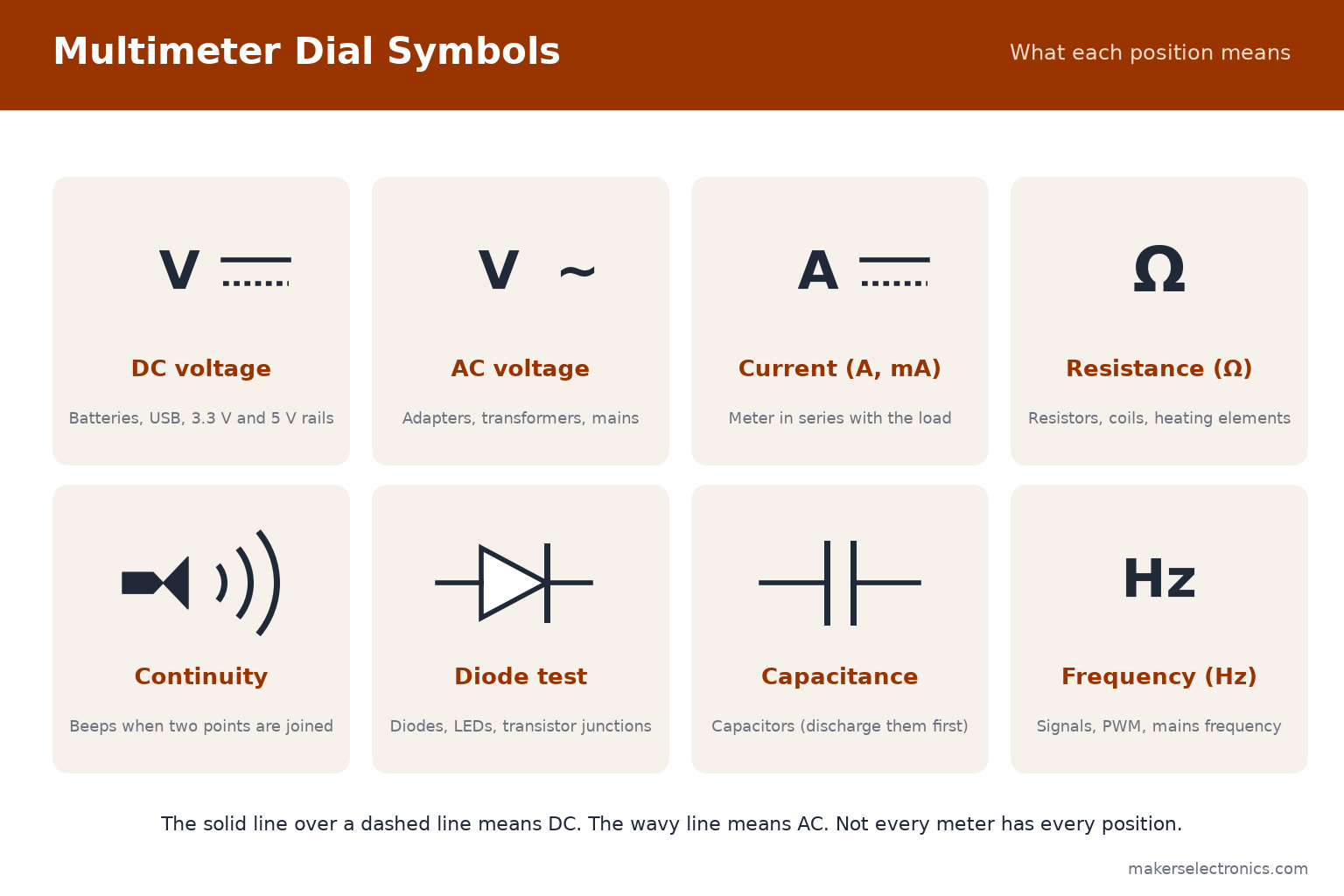
A digital multimeter (DMM) has one display, one selector dial and a few jacks. The dial chooses what it measures:
| Function | Dial symbol | Unit | Use it to check |
|---|---|---|---|
| DC voltage | V with a straight line | Volts (V) | Batteries, USB, 3.3 V and 5 V rails, power supplies |
| AC voltage | V with a wavy line | Volts (V) | Adapters, transformers, mains (with care) |
| Current | A or mA | Amps (A), milliamps (mA) | How much a circuit draws, with the meter in series |
| Resistance | Ω | Ohms (Ω, kΩ, MΩ) | Resistors, coils, heating elements, wires |
| Continuity | Sound-wave symbol | Beep | Wires, fuses, switches, solder joints, PCB tracks |
| Diode test | Diode symbol | Volts (forward drop) | Diodes, LEDs, transistor junctions |
| Capacitance, frequency, temperature | Capacitor, Hz, °C | F, Hz, °C | Capacitors, signals, probes (only on meters that have them) |
Meters are described by their counts. A 6000-count meter can show values up to 5999, which gives finer readings than a 2000-count meter. Most hobby and bench work is comfortable with a 4000 to 6000 count meter.
3. Parts of a Multimeter and the Right Jacks
Most handheld meters have four jacks. The black probe always goes in COM. The red probe changes jacks depending on what you measure:
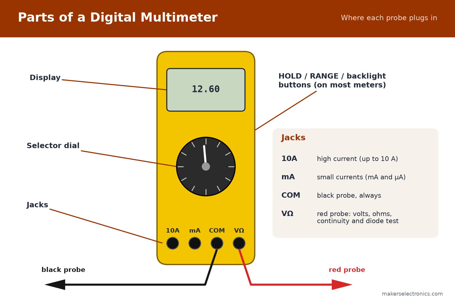
| Measurement | Red probe jack | Dial position |
|---|---|---|
| Voltage (DC or AC) | VΩ | V (straight line for DC, wavy line for AC) |
| Resistance, continuity, diode test | VΩ | Ω, continuity or diode symbol |
| Small current (mA and µA) | mA (or µA/mA) | A or mA range |
| Large current (up to the meter’s limit, often 10 A) | 10A | A range |
Many meters are auto-range: they choose the range for you. On a manual-range meter, start from the highest range and step down until the reading is clear. Buttons such as HOLD (freezes the reading), REL (zero the reading) and the backlight vary by model, so check the manual.
4. Safety First
A multimeter is safe when it is used within its rating. Follow these rules every time:
- Check the probes and leads for cracks and bare metal before use. Do not use damaged leads.
- Never measure resistance, continuity or diodes on a circuit that is powered. Switch off and discharge capacitors first.
- Make sure the red probe is in the right jack before you touch the circuit. The mA and 10A jacks are for measuring current only.
- Connect the black (COM) probe first, then the red probe. Remove the red probe first.
- Keep your fingers behind the finger guards of the probes and do not touch the metal tips.
- Work with one hand where you can, and do not stand on a wet floor when working near mains.
- Mains electricity is dangerous. Egypt’s mains is about 220 V AC at 50 Hz. If you are not trained to measure it, do not.
- If you replace a fuse inside the meter, use the same type and rating that the manufacturer specifies.
Meters carry a CAT rating (measurement category) from CAT I to CAT IV, followed by a voltage such as 600 V. The higher the category, the closer the place you measure is to the power source, and the more energy is available during a fault. For electronics work with low voltages, a CAT II meter is enough. If you measure sockets or distribution boards, choose at least CAT III with a voltage rating that matches your installation. The rating applies to the meter together with its probes: use the probes that came with it. See the measurement category overview for the definitions.

5. How to Measure DC Voltage
DC voltage is what batteries, USB ports and electronic circuits use. The meter goes in parallel with the part: across it, with the circuit powered.
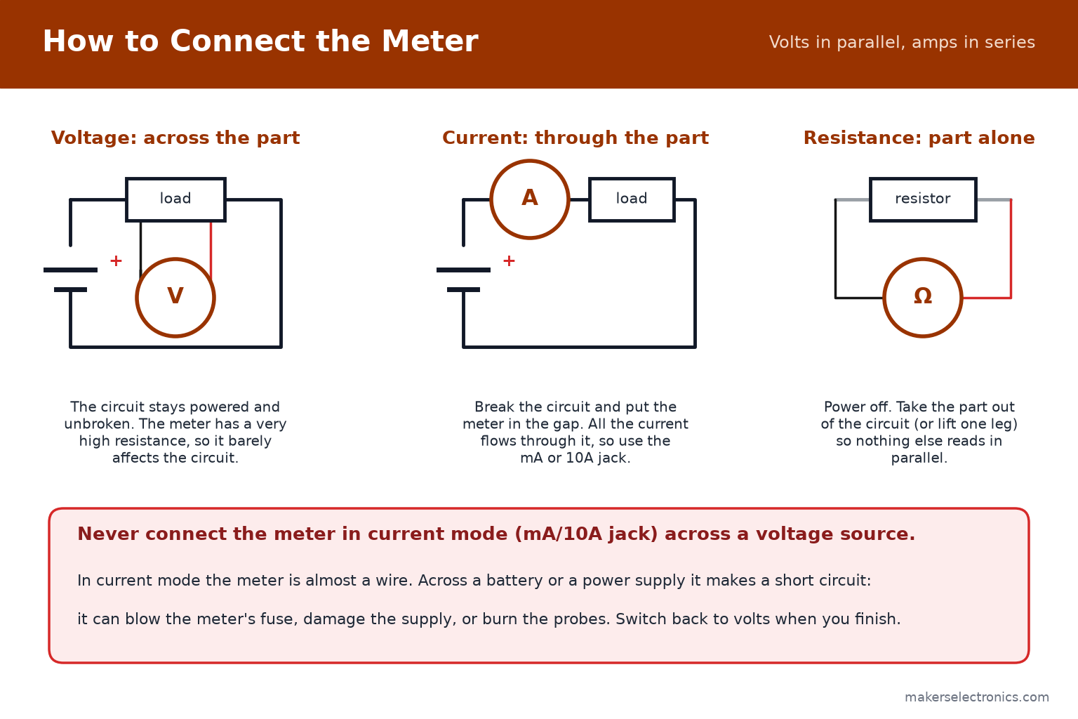
- Plug the black probe in COM and the red probe in VΩ.
- Turn the dial to DC voltage (V with a straight line). On a manual-range meter, choose a range above the expected voltage.
- Touch the red probe to the positive point and the black probe to the negative point (or ground).
- Read the display. A minus sign means the probes are reversed, which is harmless.
Compare what you read with these typical values. A reading far from them usually points to the problem:

Measure a battery or a supply under its normal load when you can. A weak battery can read nearly normal with nothing connected and then drop sharply when it has to deliver current. For Li-ion cells and charger boards, see our guide to the lithium-ion charger and BMS protection modules.
6. How to Measure AC Voltage
Turn the dial to AC voltage (V with a wavy line). The connection is the same as for DC, in parallel and with the circuit powered, and polarity does not matter.
Good places to practice are low-voltage AC outputs, such as the secondary of a small transformer or an AC adapter. Do not push probes into mains sockets unless you are trained and your meter and probes are rated for it.
True RMS vs average-responding: a basic meter assumes the waveform is a clean sine wave. If the signal is not (motor drives, dimmers, switching power supplies, PWM), the reading can be wrong. A True RMS meter measures the real effective value of the signal and is the better choice when you work with such loads.
7. How to Measure Current
To measure current, the meter must become part of the circuit: all the current flows through it. That is why current is the measurement where most mistakes and blown fuses happen.
- Switch the circuit off.
- Move the red probe to the mA jack for small currents, or to 10A for large currents. Keep the black probe in COM.
- Turn the dial to the A or mA range (DC for batteries and electronics).
- Break the circuit where you want to measure, for example disconnect the positive supply wire.
- Connect the meter into the gap: one probe on the supply side, the other on the circuit side.
- Switch the circuit on and read the display. Switch off before you disconnect the meter.
- Return the red probe to VΩ and the dial to voltage when you finish.
Example: an LED circuit with a 220 Ω resistor from 5 V and a red LED should draw about 13.6 mA (see the worked example in our resistors guide). If the meter shows far more, check the resistor value. If it shows zero, check the LED direction and the connections.
Never connect the meter in current mode across a battery or a power supply. In current mode the meter is almost a wire, so it creates a short circuit that can blow its fuse or damage the supply. The 10A range is meant for short measurements only, and the maximum time is given in the manual. To measure large AC currents without breaking the circuit, use a clamp meter.
8. How to Measure Resistance
- Switch the circuit off and discharge any capacitors.
- Remove the component from the circuit, or at least lift one leg. Other parts connected in parallel make the reading lower than the real value.
- Plug the probes in COM and VΩ and turn the dial to Ω.
- Touch the two probes to the two ends of the component. Do not pinch both metal tips with your fingers, because your body adds a parallel resistance.
- Read the value. OL means open circuit or a value above the range.
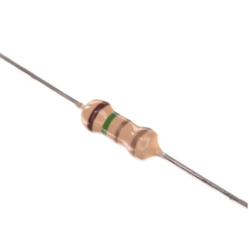
Compare the reading with the color bands or SMD code. It should fall within the tolerance of the part. To learn how to read them, see the resistors guide. For potentiometers, measure between the two outer legs to get the total value, then between the middle leg and an outer leg while turning the shaft: the reading should change smoothly.
9. Continuity Test
The continuity test tells you whether two points are electrically connected. Turn the dial to the continuity symbol (sound waves), power the circuit off, and touch the probes to the two points. The meter beeps when the resistance between them is low, usually below a few tens of ohms.
- Fuses: a good fuse beeps. A blown fuse reads OL.
- Cables and connectors: test each wire end to end, and wiggle it. A cable that beeps only sometimes has a break inside.
- Switches and buttons: the meter should beep when pressed (or closed) and stay silent when released.
- Solder joints and PCB tracks: find open joints and broken tracks. If you rework joints, see our soldering stations.
- Shorts: test between supply and ground with the power off. A beep means a short. A reading that climbs slowly from a low value is normally just the capacitors charging.
Do not use the continuity test to check if a wire is live. Use the voltage range for that, and only if it is safe to do so.
10. Diode Test
The diode test position makes the meter push a small current through the part and shows the forward voltage drop. Put the red probe on the anode and the black probe on the cathode: a good diode shows a value. Swap the probes: it should show OL.
| Part | Forward reading | Reverse reading |
|---|---|---|
| Silicon diode (for example 1N4007, 1N4148) | 0.5 to 0.7 V | OL |
| Schottky diode | 0.15 to 0.45 V | OL |
| LED | About 1.8 to 3.4 V depending on color (it may glow dimly) | OL |
| Shorted diode | 0 V in both directions | 0 V |
| Open diode | OL in both directions | OL |
The same test works as a quick check on a bipolar transistor, which behaves like two diodes. On an NPN transistor, red on the base and black on the emitter or the collector should read about 0.6 V, and the other direction should read OL. For more about transistors, see our transistors guide. Zener diodes behave as normal diodes in the forward direction. Read more in the zener diodes guide.
11. Capacitance, Frequency and Temperature
Many mid-range meters add three more functions. Check the dial to see what yours has.
- Capacitance: discharge the capacitor first. Then connect it to the meter (the meter often has a dedicated socket) and read the value. Compare it with the marking on the part. Electrolytic capacitors that read well below their value are worn.
- Frequency (Hz): measures the frequency of a signal, such as a PWM output or a square wave. Connect like a voltage measurement.
- Temperature (°C): uses a thermocouple probe plugged into the dedicated socket. Useful for checking whether a part or a heat sink is running hot.
12. Finding Why a Circuit Is Dead
When a project does nothing, work through it in this order. Each step takes a single measurement, and the first failing step shows where the fault is:

Example: an Arduino board does not power on. Measure DC volts across the USB or power jack. If it reads 5 V, measure at the 5V pin of the board. If the voltage is missing there, check the fuse, the regulator and the ground path with the continuity test. If everything reads normally and the project is still dead, look at the parts in the signal path with resistance and diode tests.
13. How to Choose a Multimeter
The right meter depends on the work. These are the features that matter most:
- CAT rating and voltage: match it to the place you measure (see the safety section).
- True RMS: important when you measure motors, dimmers, inverters and switching supplies.
- Counts and accuracy: 4000 to 6000 counts is a good starting range for electronics. Check the DC voltage accuracy in the datasheet.
- Input impedance: 10 MΩ on the voltage ranges is standard. It keeps the meter from loading the circuit.
- Auto-range makes it easier for beginners. A manual range option is faster for experienced users.
- Extras: capacitance, frequency, temperature, non-contact voltage detection, data hold, backlight and a protected current input.
- Fuses and protection: the current inputs should be protected by fuses, and replacements should be easy to get.
| Your work | Look for | Browse |
|---|---|---|
| Electronics, Arduino, ESP32 projects | 4000 to 6000 counts, auto-range, capacitance, frequency, diode test, continuity beeper | Multimeters |
| Electrical installation, panels, motors | CAT III 600 V or better, True RMS, non-contact voltage detector | UNI-T multimeters and test equipment |
| Measuring AC current without breaking the circuit | A clamp jaw, True RMS | Clamp meters |
| Labs, calibration, precise measurements | Higher resolution, bench-top form, computer interface | Benchtop multimeters |
Some examples from our range:

UNI-T UT33D+ Palm Size Multimeters

UNI-T UT890D+ Digital Multimeter

UNI-T UT121B Smart Digital Multimeter

UNI-T UT201+ Digital Clamp Meter

UNI-T UT210E Current Clamp and Multimeter

UNI-T UT8806E 6½-digit desktop digital multimeter
Specifications and availability differ by model. Check the product page for the exact rating of each meter.
14. Common Mistakes to Avoid
- Leaving the red probe in the mA or 10A jack and then measuring voltage. The meter acts as a short circuit and can blow its fuse.
- Measuring current in parallel instead of in series.
- Measuring resistance on a circuit that is still powered, or with other parts connected in parallel.
- Forgetting to switch from DC to AC (or the reverse), and then reading zero or a strange value.
- Starting with the lowest range on a manual-range meter. Start high and step down.
- Holding both metal probe tips with your fingers while measuring resistance.
- Trusting a battery reading taken with no load.
- Measuring mains with a meter or probes that are not rated for it.
15. Frequently Asked Questions
What does OL mean on a multimeter?
OL means overload or open loop. The value is above the selected range, or the circuit between the probes is open.
Why does my multimeter show a negative voltage?
The probes are reversed: the red probe is on the more negative point. The reading is correct, only the sign shows the polarity.
What is the difference between a multimeter and a clamp meter?
A multimeter measures current by being part of the circuit. A clamp meter measures current through a wire by clamping around it, with no need to break the circuit. Many clamp meters also measure voltage and resistance.
Can I test a fuse with a multimeter?
Yes. Remove the fuse, then use the continuity test or the resistance range. A good fuse beeps or reads close to 0 Ω. A blown fuse reads OL.
How do I test a battery with a multimeter?
Set the dial to DC voltage, touch the red probe to the positive terminal and the black probe to the negative one. Compare with the typical values in this guide, and measure under load if you can.
Can a multimeter measure AC current?
Some can, using an AC current range. For household and workshop loads, a clamp meter is the safer and more practical choice.
Why does my meter show a small voltage when nothing is connected?
A meter with high input impedance can pick up stray voltages from nearby wiring and show a small floating value. It is normal and disappears when the probes touch a real circuit.
Do I need a True RMS multimeter?
For batteries, USB and regular DC electronics, no. For AC loads with non-sinusoidal waveforms, such as motors, dimmers and inverters, yes.
16. Conclusion
Using a multimeter comes down to a few rules: plug the black probe into COM, choose the right jack for the red probe, put the meter across the part for voltage and through the part for current, and power the circuit off for resistance, continuity and diode tests. Compare readings with the typical values, and always keep within the meter’s CAT and voltage rating.
When you need a meter, browse the multimeters, clamp meters and UNI-T test equipment at Makers Electronics. And if you want to learn how to read the parts you measure, see our guide to resistors, color codes and SMD codes.



Leave a comment
You must be logged in to post a comment.