


Jumper Wires and Breadboards: Types, Sizes and How to Connect Them
Contents List
- Introduction.
- What Is a Breadboard and How Does It Connect?.
- Breadboard Sizes: What Do Tie Points Mean?.
- Power Rails and Split Rails.
- Jumper Wire Types: Male and Female Ends.
- Jumper Wire Lengths.
- Jumper Wire Kits.
- How to Wire a Circuit on a Breadboard, Step by Step.
- Color Coding Your Wires.
- What a Breadboard Cannot Do.
- Common Problems and How to Fix Them.
- From Breadboard to a Permanent Circuit.
- Quick Buying Guide.
- Frequently Asked Questions.
- Conclusion.
Time reading is 15min.
1. Introduction
A breadboard lets you build a circuit without soldering. You push the parts into the holes, join them with jumper wires, and change anything in seconds. It is the first tool for testing an Arduino, ESP32 or Raspberry Pi idea before it becomes a permanent board, and jumper wires are what link the breadboard to your boards, sensors and modules.
This guide explains how the holes of a breadboard are connected inside, how to read its size, what the power rails do, the three types of jumper wire and when to use each, how long they should be, how to wire a first circuit step by step, and how to find the usual faults. At the end you will find a short buying guide.
2. What Is a Breadboard and How Does It Connect?
A solderless breadboard is a plastic block with rows of small holes, spaced 2.54 mm (0.1 inch) apart, the same spacing as the pins of most electronic parts. Under each hole is a spring metal clip. When you push a lead into a hole, the clip holds it and joins it electrically to the other clips in the same strip.
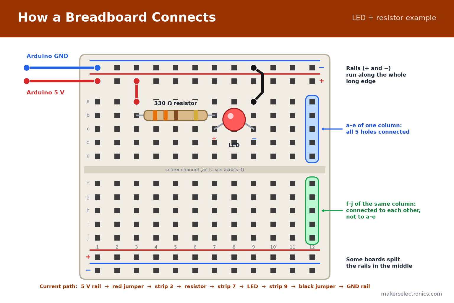
- Terminal strips (the main area): each column has two groups of five holes, rows a to e and rows f to j. The five holes of one group are connected to each other. The upper group is not connected to the lower group.
- The center channel: the gap between the two halves. A DIP chip sits across it, so the pins on the left side and the pins on the right side land on different strips and are not shorted.
- Power rails: the long lines of holes marked + and − along the edges. All holes in one rail are connected along its length, so they carry the supply and ground to every part of the board.
- Rule to remember: two component legs in the same strip are connected. Legs in different strips are not, unless you join them with a wire or another part.
In the figure, 5 V goes through a red jumper to strip 3, through the 330 Ω resistor to strip 7, through the LED to strip 9, and back to GND through a black jumper. Each part has its own strip, so each connection is deliberate.
3. Breadboard Sizes: What Do Tie Points Mean?
Breadboards are sold by the number of tie points, which is simply the number of holes that can hold a lead. More tie points means more room for parts and wires.
| Size (tie points) | What it is | Typical use |
|---|---|---|
| 170 (mini) | A very small board, usually without power rails | A single small circuit, a sensor test, a travel kit |
| 400 (half size) | One main area and one pair of rails | Learning, Arduino Uno projects with a few parts |
| 830 (full size) | The standard board: two main halves and two pairs of rails | Most projects, ESP32 or Arduino with several modules |
| 1660, 2390, 3220 | Several boards on a metal base, with more strips and rails | Large prototypes, labs, logic and teaching kits |
In board names such as BB-2T4D, the T counts the terminal (main) strips and the D counts the distribution (power) strips. The multi-board models sit on a metal base, which keeps them flat and steady on the desk.

Mini Breadboard 170 Pin

Breadboard 400 points

Breadboard 830 Point Splitted Power Rails
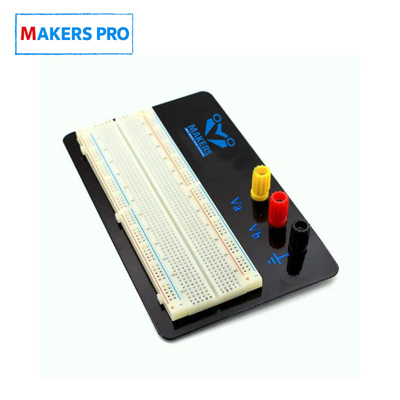
MAKERS PRO ZY-201 Solderless Bread Board 830 Points With Metal Base
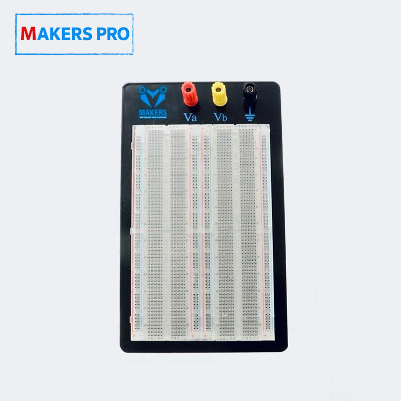
MAKERS PRO ZY-204 Bread Board 1660 Tie Point BB-2T4D With Metal Base

MAKERS PRO ZY-206 Bread Board 2390 Tie Point BB-3T5D With Metal Base
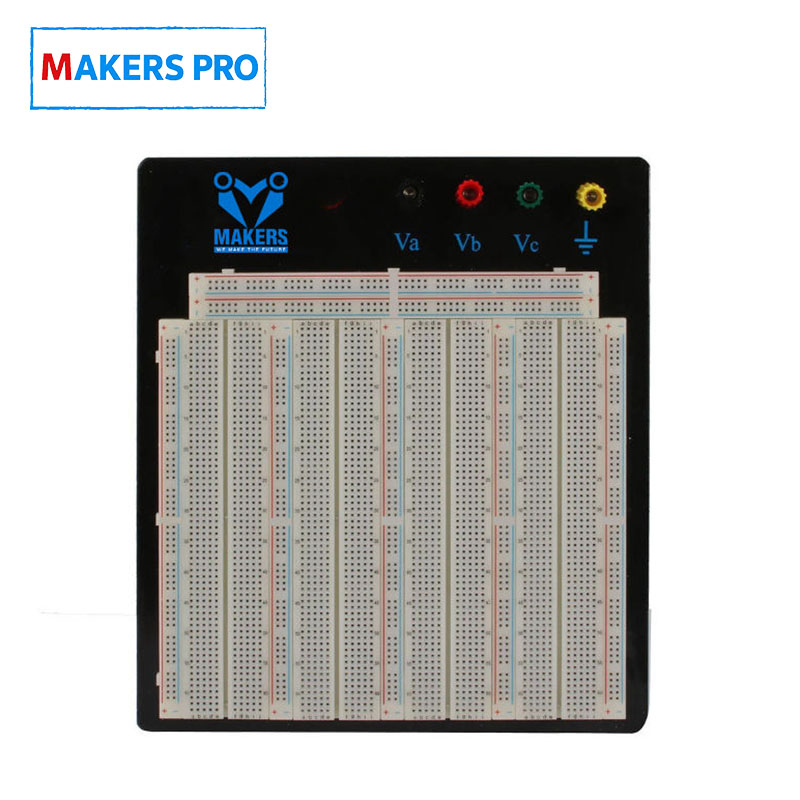
MAKERS PRO ZY-208 Bread Board 3220 Tie Point BB-4T7D With Metal Base
Which one should you pick? Wide development boards, such as many ESP32 boards, leave very few free holes beside their pins on a small board. For these boards an 830-point board is a more comfortable choice. See all options in our breadboards category.
4. Power Rails and Split Rails
The rails give you a place to bring the supply and ground once, then tap them anywhere on the board with a short jumper. A common habit is to use the red rail for the positive supply and the blue or black rail for GND.
- Split rails: on some 830-point boards the rail is broken in the middle. The left half is not connected to the right half. This is useful when you want two voltages on one board, for example 5 V and 3.3 V, but it surprises beginners who expect one continuous line.
- Joining the halves: if you want one continuous rail, bridge the gap with a jumper wire on the + rail and another on the − rail.
- Check, do not guess: set a multimeter to continuity mode and touch both ends of the rail. A beep means the rail is continuous.
- Share the ground: when you use two boards or two power supplies, connect their GND together. Without a common ground, signals between them are unreliable.
A breadboard power module plugs into the rails and gives 3.3 V or 5 V from a USB or DC supply, so you do not have to borrow power from the Arduino:

MB102 Breadboard Power Supply Module 3.3V/5V
5. Jumper Wire Types: Male and Female Ends
A jumper wire is a short flexible wire with a connector at each end. The ends are either male (a pin that plugs into a hole) or female (a small socket that fits over a pin). This gives three types, and choosing the right one depends on what is at each end of the connection.

Jumper Wire 20 cm (Male To Male Pin)

Jumper Wire 20 cm (Male to Female Pin)

Jumper Wire 20 cm (Female To Female Pin)
| You want to connect | Use |
|---|---|
| Breadboard hole to breadboard hole | Male to male |
| An Arduino Uno header (female sockets) to the breadboard | Male to male |
| A sensor or module with male pins to the breadboard | Male to female: the female end goes on the module, the male end into the breadboard |
| A sensor or module with male pins to the female header of an Arduino Uno | Male to female |
| A module with male pins to another board with male pins, such as an ESP32 board with pins soldered on | Female to female |
Browse the full range in our wires and cables category. The connectors used on most jumper wires fit the 2.54 mm pin headers, which you can see in the pin header category.
Not the same thing: a jumper shunt is a tiny plastic cap with a metal link inside. It joins two neighboring pins of a header to select a setting on a board. It is also called a jumper, but it is not a wire.

Jumper Shunt 2 Pin 2.54mm (5 Pcs)
6. Jumper Wire Lengths
The right length is the shortest one that reaches comfortably. Short wires look tidier and are easier to debug. Long wires act as antennas, add resistance, and make fast signals less reliable.
| Length | Good for |
|---|---|
| 10 cm | Neighboring parts on the same board, compact builds, wiring between two modules that sit side by side |
| 20 cm | The most useful general length: Arduino to breadboard, sensor to board |
| 30 cm | Reaching across a larger project, a sensor mounted a little away from the board |
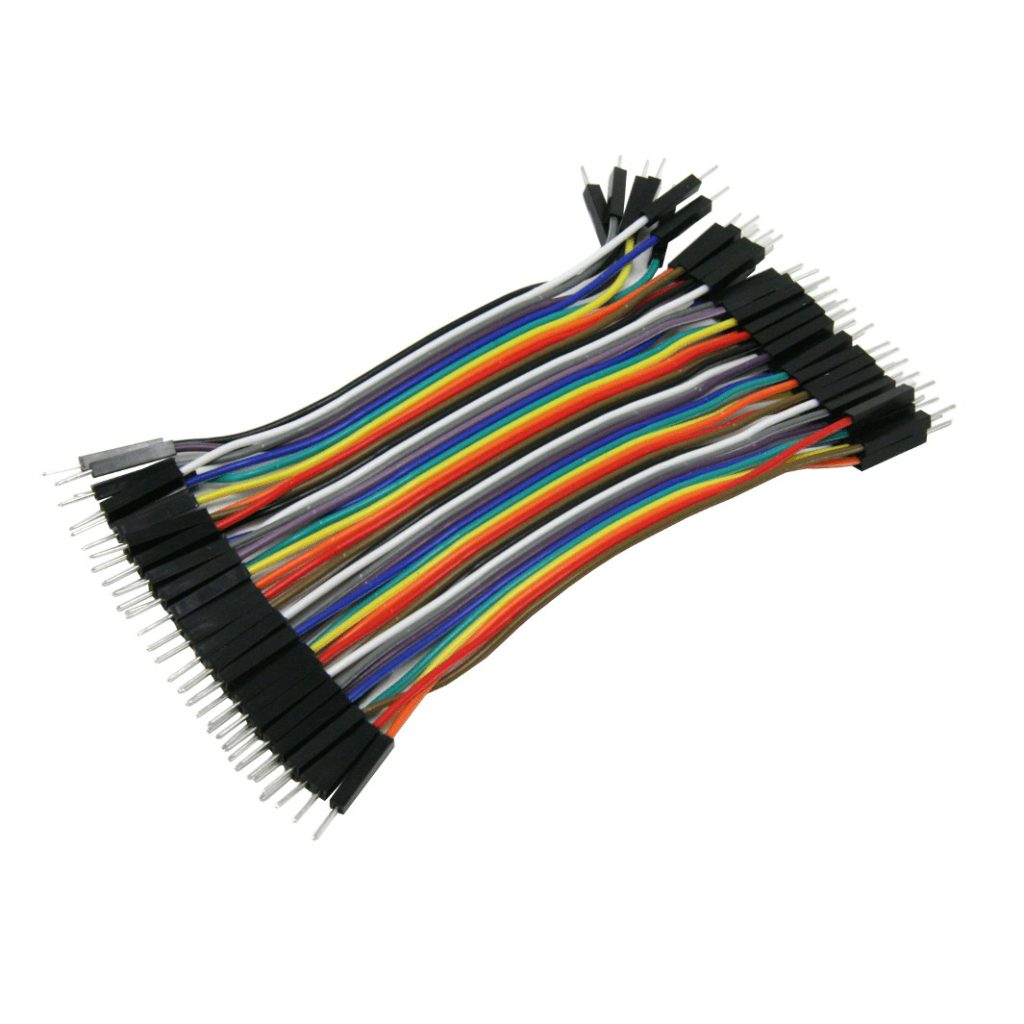
Jumper Wire 10 cm (Male To Male Pin)
Jumper Wire 20 cm (Male To Male Pin)
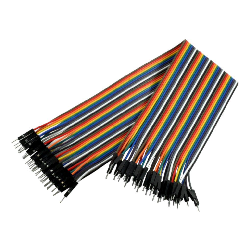
Jumper Wire 30 cm (Male to Male Pin)

Jumper Wire 10 cm (Female To Male Pin)
Jumper Wire 20 cm (Male to Female Pin)

Jumper Wire 30 cm (Male To Female Pin)
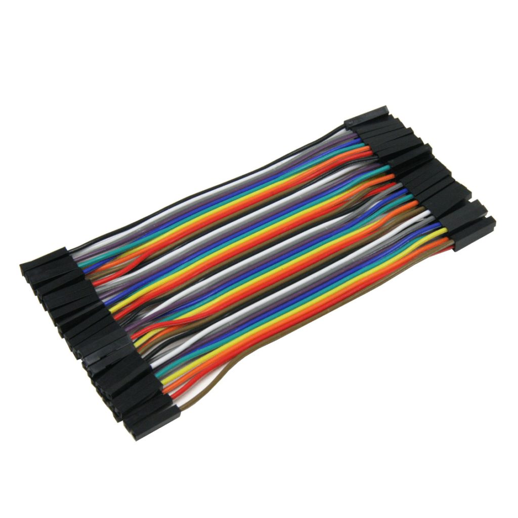
Jumper Wire 10 cm (Female To Female Pin)
Jumper Wire 20 cm (Female To Female Pin)

Jumper Wire 30 cm (Female To Female Pin)
- Signals: keep wires short for I2C, SPI and other fast buses. The protocol guide I2C vs SPI vs UART explains why wire length matters.
- Current: jumper wires are thin. They are meant for signals and small loads such as LEDs and sensors. For motors, heaters or anything that draws a high current, use thicker wire and a terminal block or soldered connections.
7. Jumper Wire Kits
When you build many circuits, a kit saves time. There are two styles:
- Dupont ribbon wires: flexible wires with plastic connectors, in colors. Good for connecting boards and modules, and for temporary wiring.
- Pre-cut breadboard wires: solid wires, pre-bent into a U shape, in assorted lengths. They lie flat on the board and make a neat, easy-to-read layout. They are meant for the breadboard only.
Breadboards accept solid wire of roughly 0.4 to 0.8 mm, about 22 AWG. Do not force thicker wire or the stripped end of a stranded cable into a hole: it opens the clip and the contact becomes loose for good.

Jumper Wires for BreadBoard & Arduino (65 Pcs)

Breadboard Jumper Wires Kit (140 Pcs)

Breadboard Jumper Wires Kit 350 Pcs

Breadboard Jumper Wires Kit (560 PCS)

Breadboard Jumper Wires Kit (840 PCS)
8. How to Wire a Circuit on a Breadboard, Step by Step
This example lights an LED from a 5 V supply. The same steps apply to any circuit.
- Switch everything off. Unplug the USB cable or the supply before you change wires.
- Place the large parts first. Modules, microcontroller boards and ICs go in first. A DIP chip sits across the center channel so each pin has its own strip.
- Wire the rails. Run a red jumper from the 5 V pin of your board to the + rail and a black jumper from GND to the − rail. If you use a split rail, bridge it.
- Add the small parts. Put the resistor between two different strips, and the LED so that its long leg (the anode, +) is on the side that goes toward the supply. Each leg goes in its own strip.
- Connect with short jumpers. Join the strips as in the figure: rail + to strip 3, resistor to strip 7, LED from strip 7 to strip 9, strip 9 to the GND rail.
- Check before you power on. Look for a wire that bridges the wrong strips, an LED the wrong way round, and two legs in one strip.
- Power on and test. If nothing lights, switch off and test continuity with a multimeter, strip by strip.
The resistor protects the LED. For a red LED that drops about 2 V at 10 mA, the value comes from Ohm’s law:
R = (5 V − 2 V) ÷ 0.010 A = 300 Ω → use 330 Ω
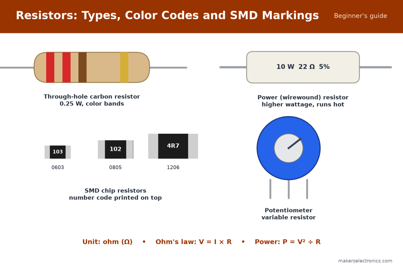
If you need help choosing the value or reading the color bands, read our guide to resistors and color codes.
9. Color Coding Your Wires
Breadboards get messy quickly. A fixed color habit makes a circuit readable for you and for anyone you ask for help:
| Color | Common use |
|---|---|
| Red | Positive supply (5 V, 3.3 V, VCC) |
| Black or blue | Ground (GND) |
| Yellow, green, white | Signals: digital pins, I2C, SPI |
| Orange or other | Special lines: reset, analog, enable |
This is a convention, not a rule, but it makes mistakes visible at a glance. Also keep wires flat against the board and avoid crossing over parts, so you can see and reach every hole.
10. What a Breadboard Cannot Do
A breadboard is a prototyping tool, and it has limits:
- Low voltage only. Never use a breadboard with mains voltage.
- Low current. The contacts and thin jumper wires are not designed for high currents. Motors, relays with high coil current, heaters and power stages need proper wiring.
- Fast and sensitive circuits. The metal strips add stray capacitance and contact resistance. High-frequency circuits and precise analog measurements behave better on a soldered board.
- Wear. The clips loosen with time and with thick leads. A board that has lost its grip causes intermittent faults, so replace it.
11. Common Problems and How to Fix Them
| Problem | Likely cause | What to do |
|---|---|---|
| Nothing works at all | A rail is not connected, or a split rail is not bridged | Check continuity along the rail and bridge the split |
| An LED does not light | The LED is reversed, or there is a missing connection | Flip the LED (long leg to +) and check each strip |
| It works only when you touch the part | A loose contact: bent lead, worn clip or thin lead | Re-seat the part, try another hole, or replace the board |
| Two parts behave as one | Two legs are in the same strip | Move one leg to a different strip |
| A chip gets hot or does not respond | The chip is on one side of the channel, shorting its pins | Place it across the center channel |
| Random resets or sensor errors | Long wires, weak supply or no common ground | Shorten the wires, use a proper supply and join the grounds |
| A wire does not fit, or a hole is loose | A lead that is too thick or stranded | Use solid wire of about 22 AWG and never force it |
To measure a live breadboard circuit, use probes with thin pins that fit the holes without damaging them:

Multimeter CAT II AVO Probes with Thin Pins for Breadboard 100cm
12. From Breadboard to a Permanent Circuit
When the circuit works, move it to a board with soldered joints. It is more reliable, it does not loosen, and it can go into a case. A prototype board (also called a perfboard or vero board) has the same 2.54 mm grid, so the layout carries over directly. Some boards copy the breadboard strips, so you can place the parts in the same positions.
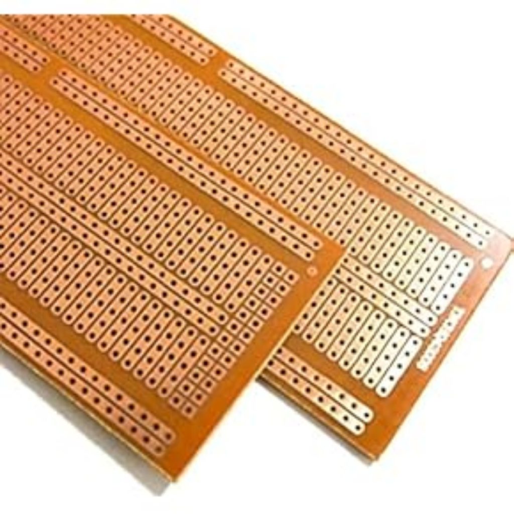
PCB Prototype Board – Vero Board FR-2 Breadboard

PCB Prototype Board – Vero Board FR-2 Center Splitted

OSEPP LS-00049 Solder-able Breadboard – Large
If you have not soldered before, start with our soldering guide for beginners, and see the soldering stations range. All prototype boards are in the PCB boards category.
13. Quick Buying Guide
| If you are… | Choose |
|---|---|
| Learning the basics | A 400- or 830-point breadboard and a 20 cm male to male kit |
| Building with an ESP32 or a wide module | An 830-point board, see the ESP32 boards page |
| Working with Arduino and sensors | An 830-point board plus male to male and male to female wires, see the Arduino boards page |
| Building a larger prototype | A multi-board model on a metal base, such as 1660 points or more |
| Building a neat final layout | Pre-cut U-shaped wires, or a prototype board and solder |
| Powering a circuit without a USB port nearby | A breadboard power module |
14. Frequently Asked Questions
What is the difference between a breadboard and a PCB?
A breadboard is a reusable, solderless board for testing. A PCB has fixed copper tracks and parts soldered to it. You prototype on the breadboard and build the final circuit on a PCB or prototype board.
How many tie points do I need?
For a first project, 400 points is enough. For most Arduino and ESP32 projects with several modules, an 830-point board gives more room.
Can I connect two breadboards together?
Yes. Join the + rails with a jumper and the − rails with another, and keep the grounds common. Many boards also have clips on the sides to snap together.
Why is my breadboard rail not connected all the way?
It is probably a split rail. Bridge the middle with a jumper on each rail, or confirm with a continuity test.
Can jumper wires carry a high current?
No. They are thin and the contacts are small. Use them for signals and small loads. For motors and other high-current parts, use thicker wire and proper connectors.
What is the difference between male and female jumper wires?
A male end is a pin that plugs into a socket or breadboard hole. A female end is a socket that fits over a pin. Choose the type by looking at the two things you want to connect.
Can I use jumper wires for the permanent version?
They are fine for temporary and demonstration setups. For anything that vibrates or must last, solder the connections or use secure connectors.
Why do my I2C sensors fail on long jumper wires?
Long wires add capacitance and noise to fast signals. Keep the wires short and use good connections.
15. Conclusion
A breadboard connects the five holes of each column together, the two halves of the board are separate, and the rails run along the edges. Pick the size for the parts you use, choose male or female jumper wires according to the two ends, keep the wires short and color-coded, and check each strip before you power on.
When you are ready to shop, see our breadboards and the jumper wires and cables. To test your circuits, read how to use a multimeter, and when the circuit is ready for a permanent build, follow our soldering guide.


Leave a comment
You must be logged in to post a comment.