



MOSFET as a Switch: Logic-Level MOSFETs, Gate Drive and How to Choose
Contents List
- Introduction.
- What Is a MOSFET and How Does It Work?.
- MOSFET vs BJT: Which One for Switching?.
- The Numbers on the Datasheet.
- Logic-Level MOSFETs and the 10 V Trap.
- A Low-Side Switch with an N-Channel MOSFET.
- Driving a Motor or Strip with PWM.
- Power Loss and Heat: P = I² × RDS(on).
- High-Side Switching with a P-Channel MOSFET.
- Choosing a MOSFET: A Checklist.
- Level Shifting and Other Small-Signal Uses.
- How to Test a MOSFET with a Multimeter.
- Common Mistakes to Avoid.
- MOSFETs and Parts to Keep in Your Kit.
- Frequently Asked Questions.
- Conclusion.
Time reading is 15min.
1. Introduction
An Arduino or ESP32 pin can only supply a few tens of milliamps. To switch a motor, a strip of LEDs, a pump, a heater or a solenoid, you need a switch that the pin can control and that can carry amps. A MOSFET is the standard answer: it is controlled by voltage, it draws almost no current at the gate, and when it is on it behaves like a very small resistor.
This guide explains how a MOSFET works, how it compares with a bipolar transistor, what logic-level really means, which numbers to read on the datasheet, how to build a low-side switch and a high-side switch, how to drive a motor with PWM, how to choose a part and how to test one with a multimeter. Every section has worked numbers you can check yourself.

IRLZ44Z N-Channel MOSFET Transistor 55V 51A Through Hole TO-220AB

IRF3205 N-Channel Power MOSFET Transistor 55V 110A 8mΩ TO-220 (Original)

IRFZ44N N-Channel Power MOSFET Transistor 49A-55V-17.5mΩ TO-220

IRF9540N P-Channel Power MOSFET Transistor 100V 23A TO-220 (Orignal)

2N7000 N-Channel Enhancement-Mode MOSFET 60V 200mA TO-92

GOODWORK AO3400 A09T SMD MOSFET Transistor SOT-23
2. What Is a MOSFET and How Does It Work?
A MOSFET (metal-oxide-semiconductor field-effect transistor) has three terminals: the gate (G), the drain (D) and the source (S). The current you want to switch flows between drain and source. The voltage between gate and source, Vgs, controls it.
- N-channel (the common type): it turns on when the gate is more positive than the source by enough voltage. It is usually placed between the load and GND: a low-side switch.
- P-channel: it turns on when the gate is more negative than the source. It is placed between the supply and the load: a high-side switch.
- Enhancement mode: the MOSFETs used for switching are off at Vgs = 0 and turn on as Vgs rises (N) or falls (P).
- Body diode: every power MOSFET has a diode inside, from source to drain in an N-channel part. It conducts in the reverse direction, which matters for motors and for testing.
The gate is insulated, so it takes current only while it is being charged or discharged. That is why a microcontroller pin can drive a MOSFET directly in many cases, and why a MOSFET is efficient: when it is fully on it behaves like a resistor with a tiny value, the on-resistance RDS(on).
3. MOSFET vs BJT: Which One for Switching?
A bipolar transistor (BJT), such as the 2N2222 or BC547, is controlled by current into its base. A MOSFET is controlled by voltage at its gate. Both can switch loads:
| BJT (2N2222, BC547, BC337) | MOSFET (IRLZ44Z, IRF540, 2N7000) | |
|---|---|---|
| Control | Base current (needs a base resistor) | Gate voltage (almost no steady current) |
| On state | Saturation voltage drop, about 0.2 V or more | A resistance RDS(on), a few milliohms for power parts |
| Loss at high current | Higher: P = Vce(sat) × I | Lower: P = I² × RDS(on) |
| Typical current | Up to about 0.1 to 0.8 A for small parts | From 0.2 A (2N7000) to over 100 A (IRF3205) |
| Best for | LEDs, relays and small loads | Motors, strips, heaters and anything above a few hundred mA |
Rule of thumb: for a small relay or an LED, a BJT is fine and cheap. Above roughly half an amp, a MOSFET wastes much less power and stays cooler. See our transistors guide for the BJT side. For parts, browse bipolar transistors and MOSFETs.

2N2222 NPN Bipolar Transistor 30V 600mA TO-92

BC547 BJT NPN Transistor 45V 100mA TO-92

BC337 NPN Amplifier Transistor 800mA 45V TO-92
BC557 BJT PNP Epitaxial Silicon Transistor -50V -100 TO-92

Tip122 5A 100V NPN Darlington Power Transistor TO-220
4. The Numbers on the Datasheet
These are the parameters that matter when you pick a MOSFET for switching:
| Parameter | Meaning | How to use it |
|---|---|---|
| VDS | Maximum drain-source voltage | At least 1.5 to 2 times the supply voltage, to survive spikes |
| ID | Maximum continuous drain current | At least 2 times your load current; it depends on cooling |
| RDS(on) | On-resistance at a stated Vgs | Lower is better. Read it at YOUR gate voltage |
| Vgs(th) | Gate threshold: where it just starts to conduct | NOT the voltage for full turn-on |
| Vgs(max) | Maximum gate voltage, usually ±20 V | Never exceed it, or the gate oxide is destroyed |
| Qg / Ciss | Gate charge / input capacitance | Bigger means slower switching and more gate current at high PWM frequency |
Example from our listings: an IRF3205 is shown as 55 V, 110 A and 8 mΩ; an IRFZ44N as 55 V, 49 A and 17.5 mΩ; an IRF540 as 100 V and 33 A; an IRF520 as 100 V, 9.2 A and 0.27 Ω. These RDS(on) values are measured at a gate voltage of about 10 V, so they are not what you get from a 5 V or 3.3 V pin. That is the point of the next section.
5. Logic-Level MOSFETs and the 10 V Trap
Many classic power MOSFETs, such as the IRF520, IRF540, IRFZ44N and IRF3205, are specified at a gate voltage of 10 V. Driven from a 5 V Arduino pin, they conduct only partly: RDS(on) is much higher than the headline value, the part heats up, and the load may not get full voltage. On 3.3 V boards (ESP32, ESP8266) it is worse.
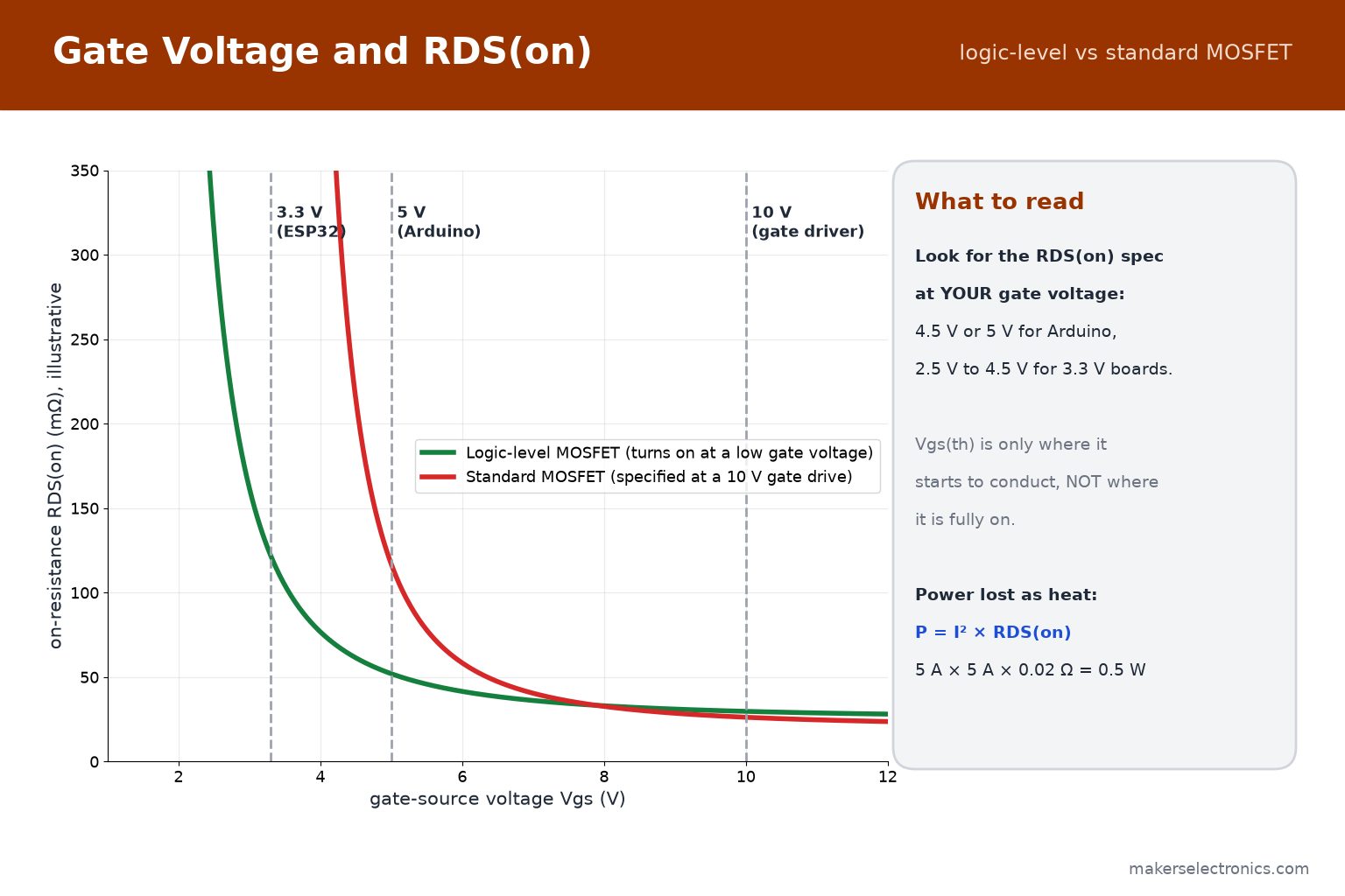
- Logic-level MOSFETs are designed to be fully on at 4.5 V or 5 V, and some at 2.5 V. The letter L in the name often marks them, as in the IRLZ44Z.
- Small SMD parts such as the AO3400, SI2302 and 2N7002K work from 3.3 V or 5 V for small and medium loads. The SI2302 is listed with a threshold of 1.1 V, and the 2N7002K with 1.7 Ω at 4.5 V.
- How to check: find the table or graph of RDS(on) versus Vgs in the datasheet and read the value at your gate voltage. If the datasheet only gives RDS(on) at 10 V, assume it is not a logic-level part.
- If you must use a 10 V part, drive its gate from a 12 V stage (a transistor or a gate-driver IC such as the TLP250 optocoupler driver) instead of from the microcontroller pin.
Many cheap ‘IRF520 MOSFET driver modules’ have exactly this problem: they work for small loads on 5 V, but heat up and lose voltage on larger ones.
IRLZ44Z N-Channel MOSFET Transistor 55V 51A Through Hole TO-220AB

2N7002K 7002 N Channel MOSFET SMD 60V 340mA 0.35W 1.7Ω@4.5V SOT-23

GOODWORK SI2302 N-Channel MOSFET Transistor SMD 1.1V@250uA SOT-23
GOODWORK AO3400 A09T SMD MOSFET Transistor SOT-23
SI2300 2300 20V 3A 35mΩ@4.5V,3.6A 0.4W N Channel SOT-23 SMD MOSFET

BSS138 SMD MOSFET Transistor 50V 220mA 1.7Ω@10V,220mA 350mW N Channel SOT-23

TLP250 MOSFET Transistor Driver 15V 11mA Dip-8
6. A Low-Side Switch with an N-Channel MOSFET
This is the circuit you will use most: the load connects to the supply, the MOSFET sits between the load and GND, and the microcontroller pin drives the gate.
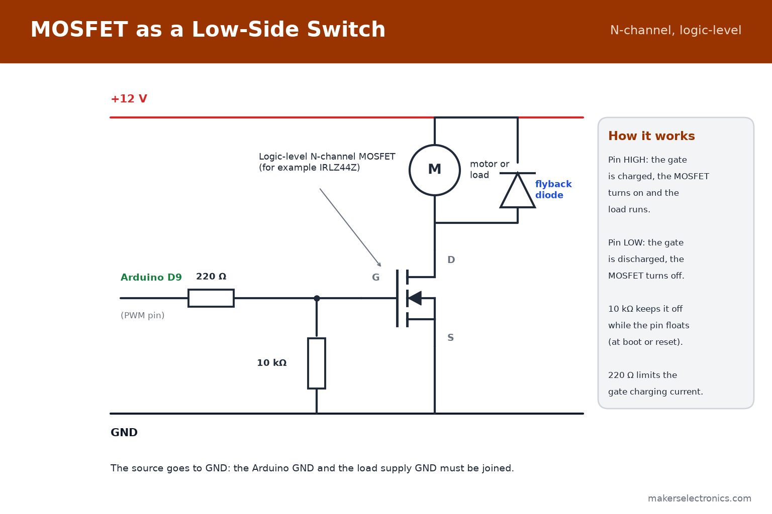
- Gate resistor (100 Ω to 220 Ω): limits the current that charges the gate capacitance and damps ringing. It also protects the pin from a short spike.
- Pull-down resistor (10 kΩ, gate to GND): keeps the MOSFET off while the pin floats, such as at power-up or while you upload a sketch. Without it, the motor may run by itself.
- Common ground: the source goes to GND, and the GND of the Arduino and the GND of the load supply must be connected.
- Flyback diode: needed for any motor, relay or solenoid. Place it across the load with the cathode to the positive supply: see our diodes guide.
- Load supply: the load voltage can be much higher than the logic voltage, for example 12 V or 24 V, as long as it is within VDS.
Use a breadboard and jumper wires for testing at low current, and solder power connections for anything above a few amps, because breadboard contacts are not rated for high current. See the jumper wires and breadboards guide.
7. Driving a Motor or Strip with PWM
To control the speed of a DC motor or the brightness of a strip, switch the MOSFET on and off fast with PWM (pulse-width modulation). The average voltage on the load follows the duty cycle.
// N-channel MOSFET gate on pin 9 (PWM), motor on the drain side
const int MOSFET_PIN = 9;

void setup() {
  pinMode(MOSFET_PIN, OUTPUT);
}

void loop() {
  analogWrite(MOSFET_PIN, 64);    // about 25 % speed
  delay(2000);
  analogWrite(MOSFET_PIN, 128);   // about 50 % speed
  delay(2000);
  analogWrite(MOSFET_PIN, 255);   // fully on
  delay(2000);
  analogWrite(MOSFET_PIN, 0);     // off
  delay(2000);
}
- Frequency: the default analogWrite on an Arduino Uno is about 490 Hz on most pins, which suits motors and strips. A higher frequency is quieter for motors but needs a MOSFET with a small gate charge.
- Loss in switching: a MOSFET dissipates the most heat while it is changing state. A slow gate (large resistor or weak drive) increases that heat, so keep the gate resistor at 100 Ω to 220 Ω for PWM.
- Current rating: check that the MOSFET and the wires can carry the stall current of the motor, which is several times the running current.
For a strip of LEDs on 12 V, the same circuit works with a single N-channel MOSFET per color channel. See our LED guide for LED basics, and our WS2812 guide for addressable strips, which need no MOSFET.
8. Power Loss and Heat: P = I² × RDS(on)
When a MOSFET is fully on, the heat it makes is the current squared times RDS(on):
P = I² × RDS(on)
- Example 1: RDS(on) = 20 mΩ (0.02 Ω) and a 5 A load: P = 5² × 0.02 = 0.5 W. A TO-220 part runs warm without a heat sink.
- Example 2: the same part at 10 A: P = 10² × 0.02 = 2 W. It needs a heat sink or a lower RDS(on).
- Example 3: the same part driven from a weak gate, with RDS(on) rising to 100 mΩ at 5 A: P = 5² × 0.1 = 2.5 W. This is the cost of a gate voltage that is too low.
Also remember that RDS(on) rises with temperature, often to about 1.5 times its 25 °C value when the part is hot. As a rule, a TO-220 MOSFET can dissipate roughly one to two watts without a heat sink. Above that, mount it on a heat sink, with an insulating pad if the tab must be isolated, since the tab is usually connected to the drain.
9. High-Side Switching with a P-Channel MOSFET
Sometimes the load must stay connected to GND and the switch must be on the positive side, for example on a car-style supply or with shared grounds. For that you use a P-channel MOSFET, with its source to the supply. It turns on when the gate is lower than the source by more than its threshold.
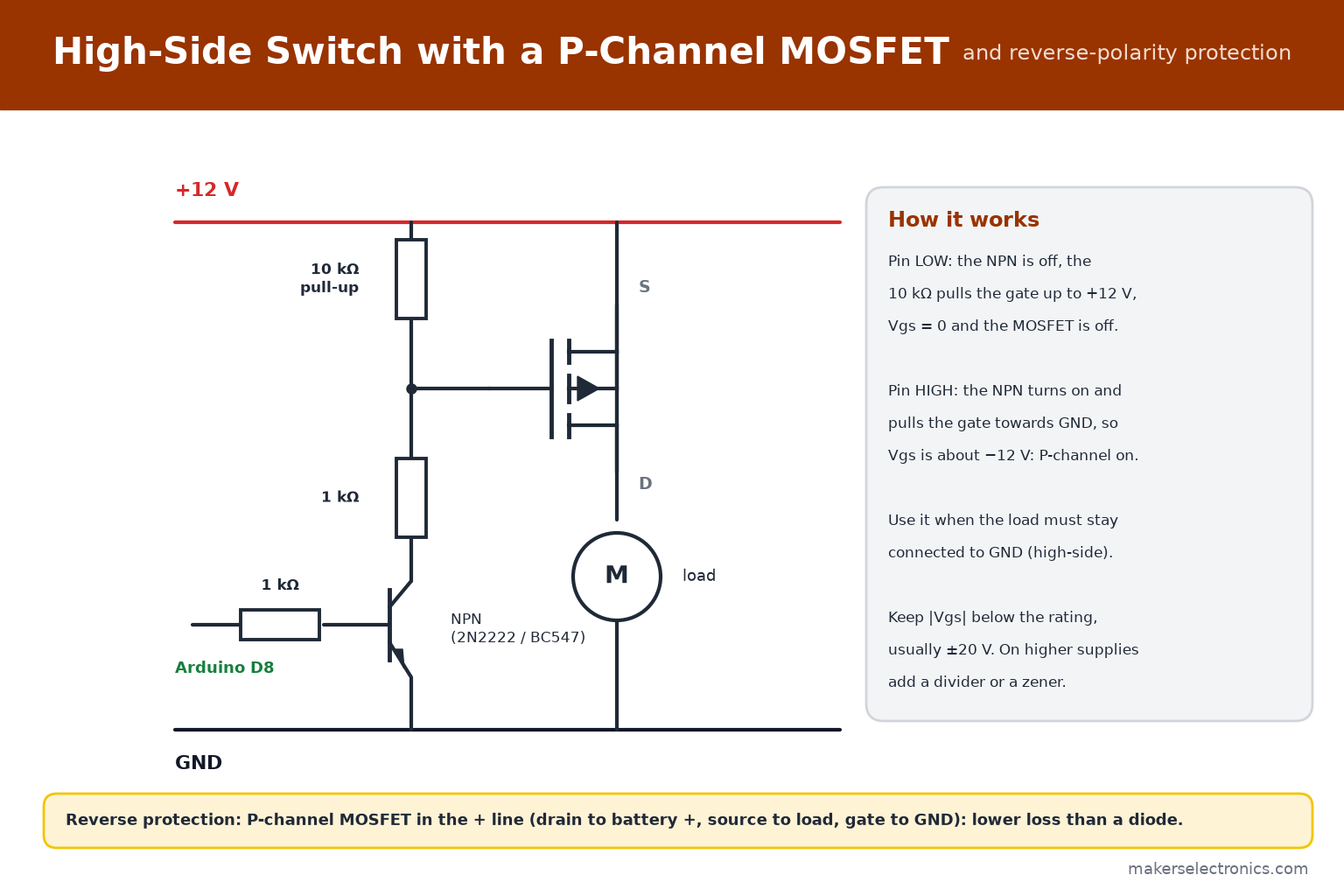
- Off state: the pull-up resistor holds the gate at the supply voltage, so Vgs = 0 and the MOSFET is off.
- On state: the small NPN (2N2222 or BC547), driven from the microcontroller, pulls the gate towards GND. Vgs becomes about −12 V and the P-channel turns on.
- Why the NPN: the microcontroller cannot pull a 12 V gate up to 12 V to turn the MOSFET off. The NPN and the pull-up solve that. Keep |Vgs| within the rating, usually ±20 V.
- Typical parts: IRF9540N (100 V, 23 A), IRF5305 (55 V, 31 A) and IRF9530 (100 V, 14 A) in TO-220, and AO3401 or BSS84 in SMD for small loads.
IRF9540N P-Channel Power MOSFET Transistor 100V 23A TO-220 (Orignal)

IRF5305 P-Channel Power MOSFET 55V 31A TO-220

IRF9530 P-Channel Power MOSFET Transistor 100V 14A 0.2Ω TO-220

AO3401 30V 4.2A 65mΩ@10V,4.2A 350mW P Channel SOT-23(TO-236) MOSFET SMD
BSS84 PD 50V 130mA 10Ω@5V,100mA 360mW P Channel SOT-23 SMD MOSFET
Reverse-polarity protection is another use: a P-channel MOSFET in the positive line, with its drain to the battery positive, its source to the load and its gate to GND, passes current with almost no drop when connected correctly and blocks a reversed supply. Compared with a diode, the loss is a fraction (see the figure and the diodes guide).
10. Choosing a MOSFET: A Checklist
- Type: N-channel for a low-side switch (the usual case). P-channel only when you need a high-side switch.
- Gate voltage: logic-level for 5 V or 3.3 V control. If the datasheet gives RDS(on) only at 10 V, drive the gate from 10 V or more.
- VDS: at least twice the supply voltage (for example 60 V parts on a 24 V supply).
- ID and RDS(on): pick RDS(on) so that I² × RDS(on) stays within the heat you can remove. Choose ID at least 2 times the load current.
- Package: TO-92 or SOT-23 for small loads, TO-220 for several amps, TO-247 for very high power.
- Extras: check Vgs(max), gate charge for high PWM frequency, and whether the body diode current rating suits an inductive load.
| Job | Example parts in our range |
|---|---|
| Small signal switching, logic level shifting | 2N7000, BSS138, 2N7002K, BSS123 |
| Small loads at 3.3 V or 5 V (LEDs, small motors) | AO3400, SI2302, SI2300, 2N7002K (SMD) |
| Motors, strips and heaters at 12 V to 24 V | IRLZ44Z (logic-level), IRF3205, IRFZ44N, IRFB4110 (with a 10 V gate drive) |
| High voltage (100 V to 500 V) | IRF540 (100 V), IRF740 (400 V) |
| High-side or reverse protection | IRF9540N, IRF5305, AO3401, BSS84 |
Browse the whole MOSFET category, SMD transistors, and bipolar transistors. Prices and availability are on each product page.
11. Level Shifting and Other Small-Signal Uses
Small MOSFETs such as the BSS138 and 2N7000 are widely used for bidirectional level shifting between 3.3 V and 5 V logic, for example on I2C lines, with a pull-up resistor on each side. They are also used as small switches for signals and as pass transistors for sensors.
- For I2C, use ready-made level shifter modules or build the standard BSS138 circuit: the gate to the 3.3 V rail, the source to the 3.3 V side, the drain to the 5 V side, and a pull-up on each side.
- For a one-way 5 V to 3.3 V signal, a resistor divider is enough for slow signals.
- Never connect a 5 V output directly to an ESP32 or ESP8266 pin.
The I2C protocol itself is explained in our I2C, SPI and UART guide.
12. How to Test a MOSFET with a Multimeter
Handle MOSFETs carefully: static electricity can destroy the gate. Touch a grounded metal object first. This test works for a typical N-channel part out of the circuit:
- Short all three pins together for a second to discharge the gate.
- Set the multimeter to the diode test range. See our multimeter guide for the basics.
- Put the red probe on the source and the black probe on the drain. You should see the body diode, about 0.4 to 0.7 V. The reverse direction shows OL.
- Touch the red probe to the gate (with the black probe still on the source) for a moment, then move the red probe back to the drain. Now the channel is on and the meter shows a very low reading, near 0 V, in both directions.
- Short the gate to the source again to turn the MOSFET off. The drain-source reading returns to OL in the reverse direction.
If the drain and source read near 0 V in both directions without touching the gate, the MOSFET is shorted. A reading of OL that never changes when the gate is touched suggests a dead or open part, but a high-threshold part may need a longer touch, so also test it in a circuit. Browse the UNI-T multimeters and the multimeter category.
13. Common Mistakes to Avoid
- Using a 10 V MOSFET such as the IRF520 or IRF540 from a 5 V or 3.3 V pin and expecting a full turn-on.
- Confusing the gate threshold Vgs(th) with the voltage needed for full turn-on.
- Leaving the gate floating, with no pull-down resistor.
- Forgetting the common GND between the microcontroller and the load supply.
- Leaving out the flyback diode on a motor, relay or solenoid.
- Choosing VDS too close to the supply voltage, with no margin for spikes.
- Exceeding the ±20 V gate rating, for example by driving a gate from a 24 V supply.
- Mounting a hot MOSFET with the tab touching other metal: the tab is usually the drain.
- Using a breadboard for high currents.
14. MOSFETs and Parts to Keep in Your Kit
For Arduino, ESP32 and general electronics, this set covers most needs:
| Part | Why |
|---|---|
| IRLZ44Z (a few) | Logic-level power MOSFET for motors and strips from 5 V or 3.3 V control |
| IRF3205 or IRFZ44N | General power N-channel MOSFET with a 10 V gate drive |
| IRF9540N or IRF5305 | P-channel for high-side switching and reverse protection |
| 2N7000 or BSS138 | Small signal MOSFET and level shifting |
| AO3400 or SI2302 (SMD) | Small loads on a PCB |
| 2N2222 or BC547 | Small BJT to drive a MOSFET gate or a relay |
| 10 kΩ and 220 Ω resistors | Pull-down and gate resistor |
| 1N4007 or a Schottky diode | Flyback diode for motors and relays |
Browse MOSFETs, SMD transistors and BJTs. For smoothing and decoupling around a motor supply, see our capacitors guide, and for the resistors, our resistors guide.
IRLZ44Z N-Channel MOSFET Transistor 55V 51A Through Hole TO-220AB
IRF3205 N-Channel Power MOSFET Transistor 55V 110A 8mΩ TO-220 (Original)
IRFZ44N N-Channel Power MOSFET Transistor 49A-55V-17.5mΩ TO-220
IRF9540N P-Channel Power MOSFET Transistor 100V 23A TO-220 (Orignal)
2N7000 N-Channel Enhancement-Mode MOSFET 60V 200mA TO-92
BSS138 SMD MOSFET Transistor 50V 220mA 1.7Ω@10V,220mA 350mW N Channel SOT-23
2N2222 NPN Bipolar Transistor 30V 600mA TO-92
15. Frequently Asked Questions
Can I drive a MOSFET directly from an Arduino pin?
Yes, if it is a logic-level MOSFET (for example the IRLZ44Z) and the load current is within its rating. Add a 100 Ω to 220 Ω gate resistor and a 10 kΩ pull-down.
Why does my IRF520 or IRF540 get hot at 5 V?
Because it is not fully on at 5 V: its RDS(on) is specified at 10 V. Use a logic-level MOSFET or drive the gate with a 10 V to 12 V stage.
Do I need a gate resistor?
It is recommended: 100 Ω to 220 Ω limits the gate charging current and reduces ringing. For slow, small circuits it can be omitted, but it costs almost nothing.
Can I use an N-channel MOSFET on the positive side?
It needs a gate voltage higher than the supply to turn on, which requires a driver. For simple projects, use a P-channel MOSFET for the high side, or keep the switch on the low side.
What does the letter L in IRL… mean?
It usually marks a logic-level part, one that is fully on at 4.5 V to 5 V of gate drive, compared with IRF… parts specified at 10 V.
Why did my motor run when I uploaded a sketch?
During upload the pin floats. Without a pull-down resistor the gate can charge by itself and turn the MOSFET on. Add a 10 kΩ resistor from gate to GND.
Is the MOSFET body diode a problem?
It conducts in the reverse direction, which is useful for freewheeling current from inductive loads, but it also means a reversed supply is not blocked by an N-channel switch. Use a P-channel protection MOSFET or a diode for that.
Can I use a MOSFET for AC loads?
A single MOSFET switches DC. For AC loads use a relay, a triac or a solid-state relay, or a special back-to-back MOSFET arrangement designed for AC.
16. Conclusion
A MOSFET is the right switch for anything above a few hundred milliamps, but it must be driven properly. Read RDS(on) at your own gate voltage, use a logic-level part for 5 V and 3.3 V control, add a gate resistor and a pull-down, keep a flyback diode across inductive loads, share the ground, and check the heat with P = I² × RDS(on).
When you are ready to build, browse MOSFETs, SMD transistors and bipolar transistors at Makers Electronics.


Leave a comment
You must be logged in to post a comment.