



DC Cooling Fans: Sizes, Voltage, Wires, Speed Control and How to Choose
Contents List
- Introduction.
- How a DC Fan Works.
- Fan Sizes and Hole Spacing.
- Voltage, Current and Power.
- Two, Three and Four Wires.
- Airflow and Static Pressure.
- Bearings and Lifetime.
- Mounting and Airflow Direction.
- Powering a Fan.
- Switching a Fan with a MOSFET.
- Controlling Fan Speed.
- Using a Fan with a Heat Sink.
- Guards, Filters and Safety.
- Server and Industrial Fans.
- How to Choose a Fan.
- Troubleshooting.
- Starter Kit for Fan Projects.
- Frequently Asked Questions.
- Conclusion.
Time reading is 15min.
1. Introduction
Heat is the most common reason an electronic project fails slowly: a regulator that runs too hot, a motor driver that shuts down, a power supply that dies after a summer. A small DC fan is often the cheapest and simplest fix. But fans come in many sizes, voltages and wire counts, and choosing one by looks alone leads to a fan that does not fit, does not start, or is far louder than expected.
This guide explains how a DC fan works, how to read its size and hole spacing, how to turn voltage and current into watts, what 2, 3 and 4 wires do, the difference between airflow and static pressure, bearing types, how to mount the fan so it blows the right way, how to power it and switch it with a MOSFET, how to control its speed, how to use a fan with a heat sink, and how to troubleshoot a fan that does not behave. Every section has worked numbers that you can check against the product page.

H.R.Y 12025S12V DC Cooling Fan 12V 0.38A 120×120×25mm

H.R.Y 8025S24V DC Fan 24V 0.25A 80x80x25mm 4000 RPM 2-Pin Connector

DC Fan 5V 0.25A 60x60x25mm

YD5020HSL DC Fan 12V 0.15A 50x50x20mm

Plastic Fan Guard with Filter for 12x12cm Fan

Aluminium Black Heatsink 34x25x12mm For TO-247
2. How a DC Fan Works
Almost every small DC fan is a brushless motor. A ring of permanent magnets sits on the rotating part, coils are fixed in the frame, and a small circuit inside the fan switches the coils in the right order. A sensor (usually a Hall sensor) tells that circuit where the magnets are. Because the electronics are built in, the fan needs only a DC supply: two wires are enough to make it spin.
- No brushes means no sparks and no brush wear, so the life of the fan depends mostly on the bearing.
- The built-in circuit is why swapping the two wires does not reverse the fan. A brushless fan only turns one way, and wrong polarity makes it stay still or, on some fans, damages the circuit.
- DC fans run from low voltage (5, 12, 24 or 48 V). AC fans run directly from mains (for example 110 V or 220 V) and are a different product: see the AC fans. This guide is only about low-voltage DC fans.
- Axial fans (the common square type) move air along the shaft. Blowers push air out sideways at higher pressure.
Browse the full DC fan range and the wider cooling solutions category.
3. Fan Sizes and Hole Spacing
A fan is named by the outside size of its square frame and its thickness: 80x80x25 mm is 80 mm wide, 80 mm high and 25 mm thick. The size of the blades is smaller. When you replace a fan, or fit one onto a heat sink or a case, the number that must match is the distance between the mounting holes.
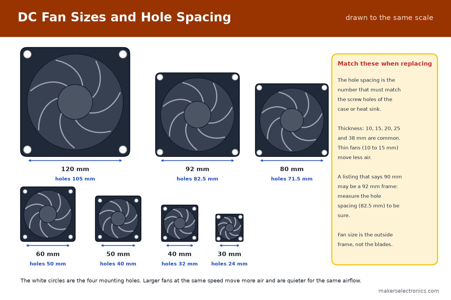
| Frame size | Hole spacing | Typical use | Example listing |
|---|---|---|---|
| 30 mm | 24 mm | Small modules and mini heat sinks | DC Fan 12V 0.09A 30x30x10mm |
| 40 mm | 32 mm | Small boards, 3D printer parts, servers | 40×40 server fans |
| 50 mm | 40 mm | Boards, small enclosures, heat sinks | YD5020HSL DC Fan 12V 50x50x20mm |
| 60 mm | 50 mm | Enclosures, amplifiers, small power supplies | DC Fan 5V 0.25A 60x60x25mm |
| 80 mm | 71.5 mm | Enclosures, power supplies, benches | DC Fan 12V 0.15A 80x80x25mm |
| 92 mm | 82.5 mm | Enclosures and larger heat sinks | YD9225HSL DC Fan 5V 90x90x25mm |
| 120 mm | 105 mm | Cases, large heat sinks, quiet cooling | H.R.Y 12025S12V DC Fan 120x120x25mm |
A larger fan can move the same air at a lower speed, which is quieter. Thickness matters too: a 25 mm fan is the common standard, a 10 to 15 mm fan fits in tight spaces but moves less air, and a 38 mm fan is thicker, stronger and usually draws more current. Some listings call a 92 mm frame “90 mm”: if you must be sure, measure the hole spacing (82.5 mm for 92 mm).
YD5020HSL DC Fan 12V 0.15A 50x50x20mm
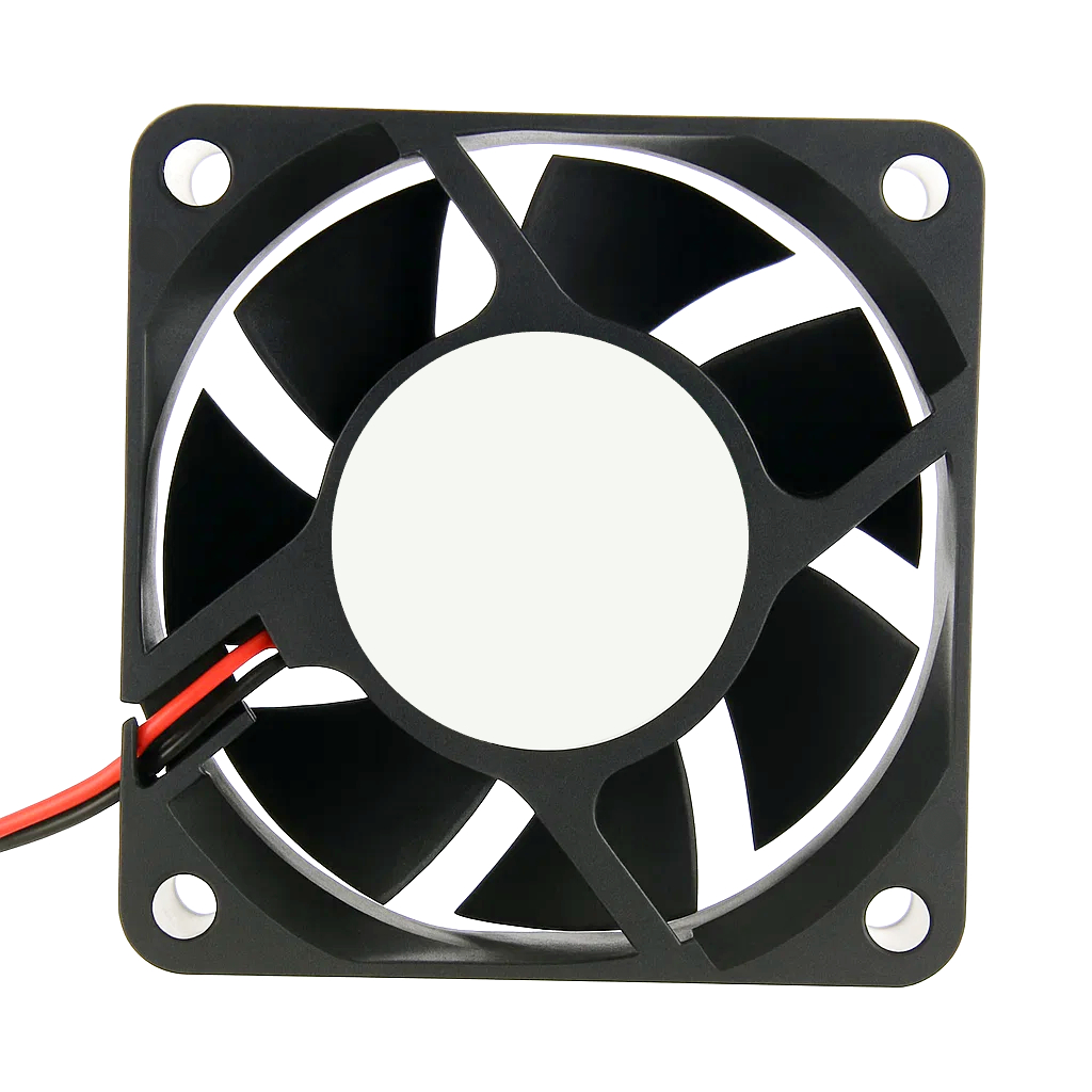
GOLDEN SUN KF0625HST DC Fan 12V 0.15A 60x60x25mm

DC Fan 12V 0.15A 80x80x25mm

YD9225HSL DC Fan 5V 0.2A 90x90x25mm
H.R.Y 12025S12V DC Cooling Fan 12V 0.38A 120×120×25mm
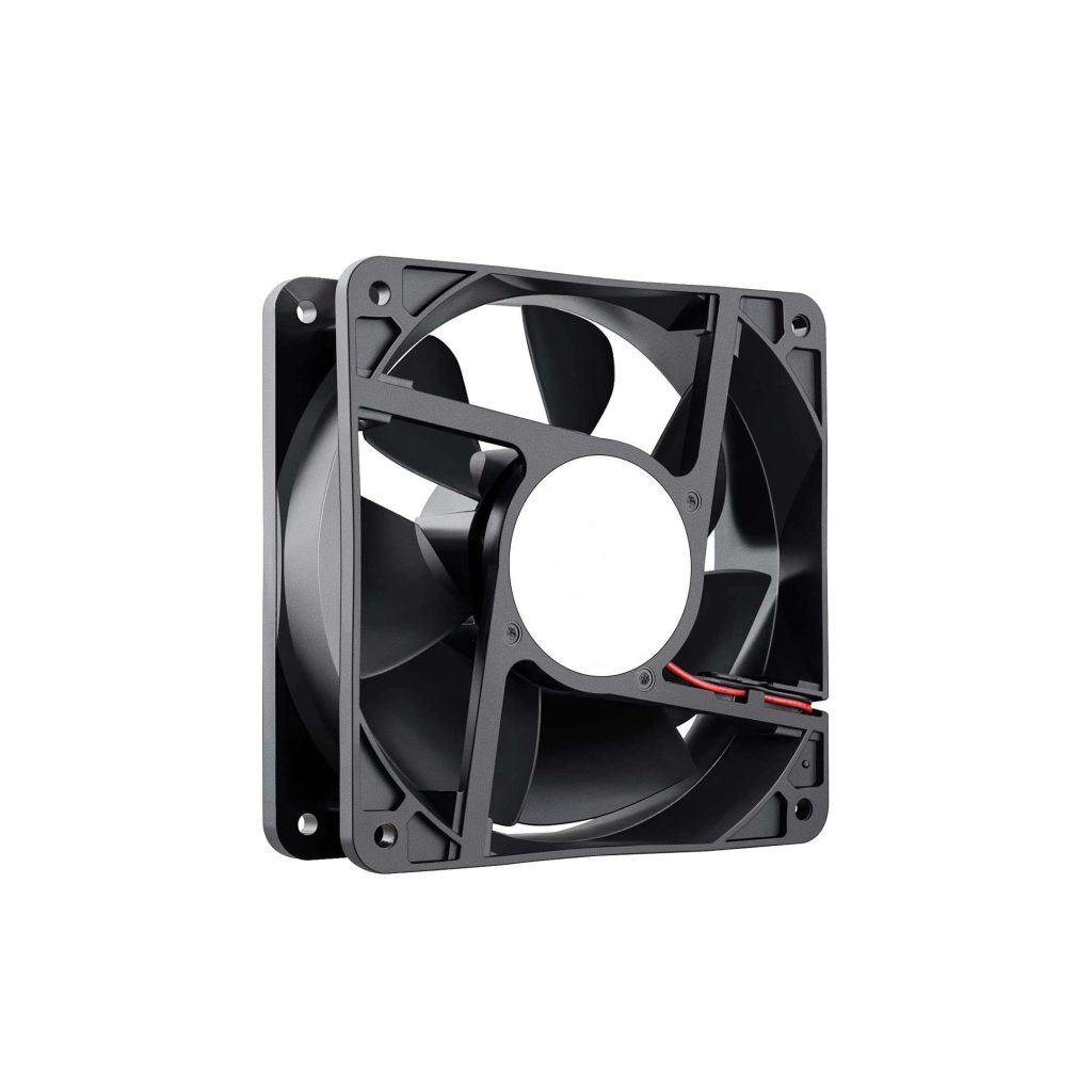
DC Fan 12V 0.35A 120x120x38mm
4. Voltage, Current and Power
The voltage printed on a fan is its rated voltage: the voltage it is designed to run at. Small fans are made for 5, 12, 24 and 48 V. Use the rated voltage, and read the current: it tells you what your supply must deliver. Power in watts is voltage times current:
Power (W) = Voltage (V) × Current (A)
| Listing | Voltage | Current | Power |
|---|---|---|---|
| DC Fan 12V 0.09A 30x30x10mm | 12 V | 0.09 A | 12 × 0.09 = 1.08 W |
| DC Fan 5V 0.25A 60x60x25mm | 5 V | 0.25 A | 5 × 0.25 = 1.25 W |
| YD5020HSL DC Fan 12V 0.15A 50x50x20mm | 12 V | 0.15 A | 12 × 0.15 = 1.8 W |
| BJC5012-S DC Fan 24V 0.08A 50x50x12mm | 24 V | 0.08 A | 24 × 0.08 = 1.92 W |
| DC Fan 12V 0.35A 120x120x38mm | 12 V | 0.35 A | 12 × 0.35 = 4.2 W |
| H.R.Y 12025S12V DC Fan 12V 0.38A 120x120x25mm | 12 V | 0.38 A | 12 × 0.38 = 4.56 W |
| H.R.Y 8025S24V DC Fan 24V 0.25A 80x80x25mm | 24 V | 0.25 A | 24 × 0.25 = 6 W |
- Several fans: add their currents. Three 12 V fans of 0.38 A need about 1.14 A from the supply.
- Margin: choose a supply that can deliver noticeably more than the total, because a fan draws more current while it starts.
- Never run a fan above its rated voltage. A 5 V fan connected to 12 V is damaged. A 12 V fan on 5 V may not start at all, and if it does it moves little air.
- Check with a meter: measure the supply voltage before you connect the fan. See how to use a multimeter.
DC Fan 5V 0.25A 60x60x25mm
YD5020HSL DC Fan 12V 0.15A 50x50x20mm

BJC5012-S DC Fan 24V 0.08A 50x50x12mm
H.R.Y 8025S24V DC Fan 24V 0.25A 80x80x25mm 4000 RPM 2-Pin Connector

Power Supply 24V 10A with Cooling Fan
5. Two, Three and Four Wires
The number of wires tells you what the fan can report and what it can be told:
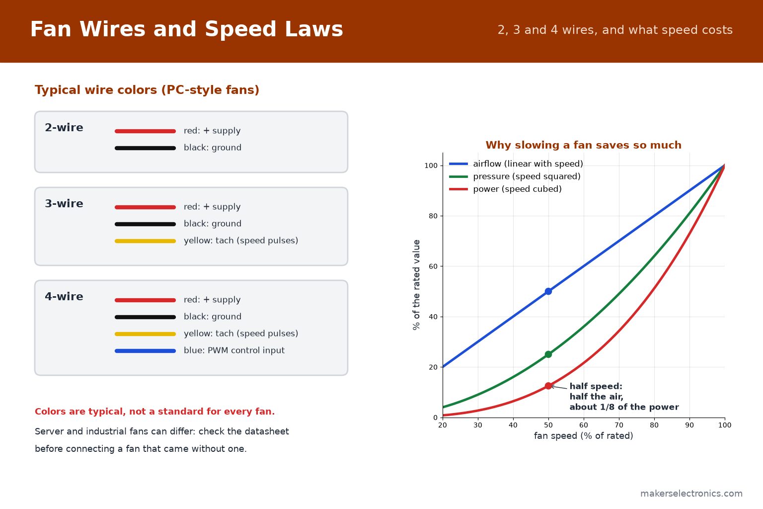
| Wires | Signals | What you can do |
|---|---|---|
| 2 | + supply and ground | Run it at full speed, or change the speed by changing the supply (voltage or PWM on the supply). |
| 3 | Adds tach | Read the real speed. The fan gives pulses, normally 2 per revolution. |
| 4 | Adds PWM input | Change the speed with a control signal while the fan stays powered. The target frequency is about 25 kHz. |
Reading the tach. Count the pulses per second and convert: RPM = pulses per second × 60 ÷ 2 for a fan that gives 2 pulses per revolution. For example, 100 pulses per second is 100 × 60 ÷ 2 = 3000 RPM. The tach output is usually open collector, so the board needs a pull-up resistor to its logic voltage.
Connectors. Small fans come with a 2-pin connector, and 3-pin or 4-pin headers on a 2.54 mm pitch are common on PC-style fans. Colors are typical but not a standard, and server fans can be wired differently, so check the datasheet. For plugs and housings see the terminal blocks and JST connectors guide and the JST connectors.
6. Airflow and Static Pressure
A datasheet gives two numbers that matter more than the size: airflow and static pressure.
- Airflow is how much air the fan moves in free air, with nothing in front of it. It is quoted in CFM (cubic feet per minute) or m³/h. 1 CFM is about 1.7 m³/h.
- Static pressure is how well the fan pushes against resistance, quoted in mmH₂O or Pa. A heat sink with tight fins, a dust filter or a narrow duct creates resistance.
- The numbers are linked: the more resistance there is, the less air the fan really moves. A fan with great airflow and low pressure can disappoint in front of a dense heat sink.
| Situation | What matters most | Choose |
|---|---|---|
| Vent holes in an open enclosure | Airflow | A larger, slower axial fan |
| A heat sink with tight fins or a long duct | Static pressure | A higher-pressure fan, often with more blades and higher speed |
| A very tight space or a blower layout | Pressure, in a small volume | A blower or a thin high-speed fan |
| A quiet bench or room | Low speed | The largest fan that fits, run slowly |
Fans with a higher speed (RPM) move more air and make more noise. For example, the H.R.Y 8025S24V listing states 4000 RPM, and the H.R.Y 12025S12V listing states 2700 RPM for a larger frame.
7. Bearings and Lifetime
In a brushless fan the bearing is the part that wears. These are the common types:
| Bearing | Advantages | Limits |
|---|---|---|
| Sleeve (plain) | Quiet, low cost | Shorter life, especially when hot. Best mounted with the shaft not pointing sideways or down. |
| Ball (single or dual) | Longer life, works in any orientation, handles heat better | Slightly more noise and cost |
| Hydraulic or other fluid bearings | Quiet with long life, in some designs | Check the datasheet of the exact fan |
Datasheets quote life in hours at a stated temperature. Life drops quickly as the fan gets hotter, so a fan that sits in the exhaust of a hot enclosure lasts less than the same fan in cool air. The H.R.Y listings show a sleeve bearing on their label, so keep the orientation in mind when you mount them.
8. Mounting and Airflow Direction
A fan that blows the wrong way is the most common beginner mistake. Look at the frame: two arrows are molded in it, one for the direction of the airflow and one for the rotation of the blades. Usually the side with the motor struts is the side the air leaves from, but always follow the arrows.
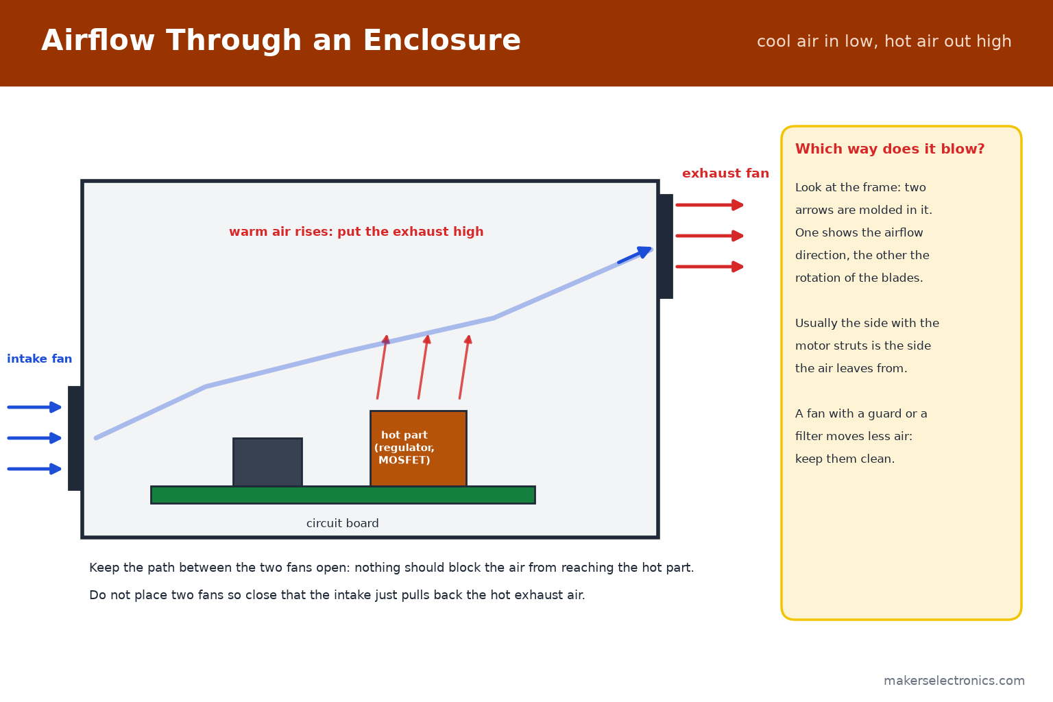
- Intake low, exhaust high. Warm air rises, so let the exhaust fan sit high and the intake fan low.
- Let the air reach the hot part. Parts and cables should not block the path between the two fans.
- Do not recirculate. If the intake and the exhaust are very close, the intake pulls back the hot air that was just pushed out.
- Mount firmly, but do not over-tighten. Four screws, or rubber mounts, to keep vibration low. Over-tight screws can distort a plastic frame.
- Keep the cable away from the blades and tie it so it cannot touch them.
- Leave some free space in front of the intake, or the fan will starve and become noisy.
9. Powering a Fan
A fan needs a supply at its rated voltage that can deliver its current. Three practical rules:
- Never power a fan from a microcontroller pin. A pin of a typical board gives about 20 mA, and even a small fan needs 100 mA or more. The pin would be overloaded.
- Use the right supply. A 5 V fan can run from a USB supply or a regulated 5 V rail with enough current. A 12 V fan needs a 12 V supply. If the board has a higher voltage and the fan needs 5 V or 12 V, use a step-down converter: see the buck converter vs LDO guide. A resistor in series to “drop” the voltage wastes power and gives a speed that depends on the load.
- Join the grounds. When a microcontroller controls a fan that has its own supply, the grounds of both must be connected.
Check the polarity before you apply power. Red is normally the positive wire and black the ground, and a reversed fan often does not run and can be damaged. When you extend the wires, use a proper connector or a soldered joint with heat-shrink: see the soldering guide.
10. Switching a Fan with a MOSFET
To turn a fan on and off from a microcontroller, or to change its speed with PWM, use a logic-level N-channel MOSFET as a switch on the ground side of the fan:
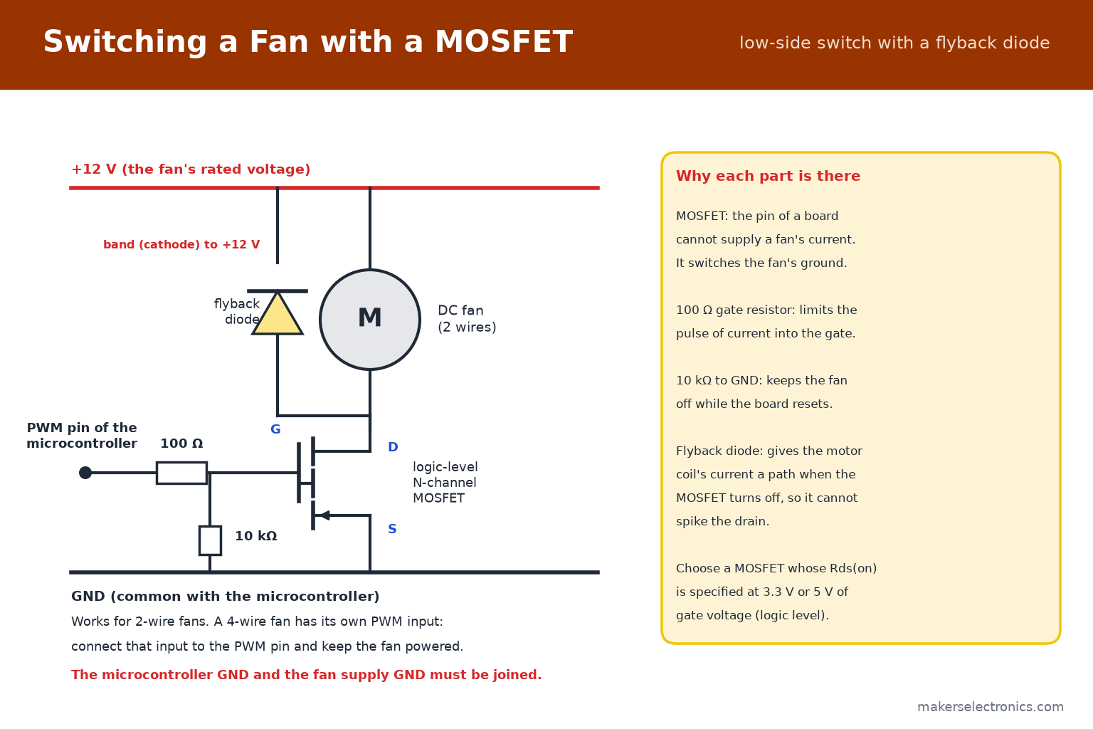
- Connect the fan between + supply and the drain of the MOSFET. The source goes to ground.
- Connect the microcontroller pin to the gate through a 100 Ω resistor, and add a 10 kΩ resistor from the gate to ground so the fan stays off while the board resets.
- Put a flyback diode across the fan, with the band (cathode) toward the positive supply. It gives the current of the motor coil a path when the MOSFET turns off.
- Join the ground of the microcontroller and the ground of the fan supply.
Choosing the MOSFET. It must be logic level: its on-resistance Rds(on) is specified at the gate voltage your board gives (3.3 V or 5 V). Fan currents are small, so the MOSFET stays cool: with a 0.38 A fan and a MOSFET of 0.05 Ω, the loss is 0.38² × 0.05 ≈ 0.007 W. See the full MOSFET as a switch guide for gate drive, and the diodes guide for the flyback diode.
PWM frequency. A typical Arduino Uno gives about 490 or 980 Hz, and a fan can whine at that frequency. A higher frequency, up to about 25 kHz, is quieter. Some fans with built-in electronics do not like a chopped supply, especially at low duty cycles, so test the fan you use. A 4-wire fan avoids the issue because it has its own PWM input.
Browse MOSFET transistors and read the transistors guide for small fans that a BJT can switch.
11. Controlling Fan Speed
A fan at full speed is often louder than needed. Slowing it reduces noise and power a lot, because airflow follows speed, pressure follows speed squared, and power follows speed cubed (see the chart in the wires figure). At half speed a fan moves about half the air with about one eighth of the power.
| Method | How | Notes |
|---|---|---|
| Lower the voltage | A step-down converter with an adjustable output, or a speed controller module | Simple. Many fans will not start below roughly half of their rated voltage, so test the lowest setting. |
| PWM on the supply of a 2-wire fan | A MOSFET switch driven by PWM | Quiet at a high frequency. Loses the tach reading. |
| The PWM input of a 4-wire fan | A PWM signal at about 25 kHz on the control wire | Best control. The fan stays powered and the tach still works. |
| Automatic by temperature | A temperature sensor and a microcontroller that sets the duty cycle | The fan runs slowly when cool and faster as the temperature rises. |
For small USB-powered fans, a ready-made module with a knob can be enough: the HW-602 USB fan speed controller is listed in the store, and its page gives the supported voltage. Check that the fan and the module use the same voltage.

HW-602 USB Fan Governor Wind Speed Controller
DC Fan 5V 0.25A 60x60x25mm
YD9225HSL DC Fan 5V 0.2A 90x90x25mm
12. Using a Fan with a Heat Sink
A heat sink spreads heat into more surface, and a fan makes that surface far more effective, because moving air takes heat away much faster than still air. The temperature of the part follows the thermal resistances in series:
Part temperature = Ambient + Power × (Rθ junction-case + Rθ case-sink + Rθ sink-air)
Example. A part dissipates 6 W and the total thermal resistance is 8 °C/W. The rise is 6 × 8 = 48 °C, so in a room at 25 °C the part reaches about 73 °C. The airflow of a fan lowers the sink-to-air resistance, and the heat sink datasheet usually shows by how much for a given airflow. The same 6 W then gives a smaller rise.
- Contact first. The part must press flat against the heat sink, with thermal paste or a pad, and a firm screw. A great fan does not help a loose heat sink.
- Blow along the fins. The air must pass between the fins, not hit them from the side with no way out.
- Match the size. The fan should be about the size of the finned area, so no fins are left in still air.
- Do not forget the rest of the box. A fan on the heat sink moves heat into the enclosure, which still needs an exhaust.
The range includes heat sinks for small parts such as TO-220 and TO-247 packages and for motor driver chips. Browse the heat sinks and read the MOSFET guide for how to estimate the power a part dissipates.

Aluminium Heatsink 20x15x10mm For TO-220
Aluminium Black Heatsink 34x25x12mm For TO-247

Aluminium Heatsink For L298 25x24x15mm

Aluminum Heatsink U SHAPE 20x19x10mm
13. Guards, Filters and Safety
A spinning fan can hurt a finger, and a fan in a dusty place slowly fills with dust. A guard and a filter solve both, at a small cost in airflow.
- Finger guards (the metal wire type) protect the blades and the user. Choose one that matches the frame size.
- Filters catch dust. A clogged filter reduces the airflow a lot, so clean it from time to time.
- Wires and loose items must stay away from the blades. A cable caught in a fan can stall it or tear.
- Mains fans are a different job. An AC fan carries mains voltage and should only be wired by someone trained to do it.

Chrome Fan Guard for Case Fan
Plastic Fan Guard with Filter for 12x12cm Fan
14. Server and Industrial Fans
The range also lists many server and industrial fans from makers such as Delta, Sanyo Denki, Nidec, Sunon and Papst, listed as used like new. They are built for high airflow and long life, and they differ from small fans:
- Higher current and power. A 12 V server fan can draw 1 to 4 A, which is 12 to 48 W. Make sure the supply and the wires can carry it.
- Higher speed and noise. They are designed for pressure and airflow, not for quiet.
- 48 V versions exist for telecom and industrial use. Do not mix them with 12 V supplies.
- 4-wire and special connectors. Many have a PWM input and a tach, and some have 6 pins. Find the datasheet by the part number and check the pinout before you connect power.
- Used. They are listed as used, so test one with a supply that can deliver its rated current.
Browse the DC fan category and filter by the voltage and size you need.
15. How to Choose a Fan
Go through these steps in order:
- Space: measure the room for the fan, and the hole spacing if it screws onto something.
- Voltage: match the supply you have: 5, 12, 24 or 48 V.
- Current: check that the supply can deliver the fan current, with margin.
- Airflow or pressure: open vent means airflow, heat sink or filter means pressure.
- Noise: prefer the largest fan that fits, run slowly.
- Wires: 2 wires for on and off, 3 to read the speed, 4 for PWM control.
- Bearing: ball for long life or any orientation, sleeve for quiet and low cost.
- Extras: a guard, a filter, a connector and the screws.
| Your project | A good starting point |
|---|---|
| A small 3.3 or 5 V board that runs warm | A 30 or 40 mm fan at 5 V |
| A box with a 12 V power supply | A 60 or 80 mm fan at 12 V, intake and exhaust |
| A heat sink on a power part | A 40 to 60 mm fan that blows along the fins |
| A large heat sink or a quiet case | A 120 mm fan at low speed |
| A 24 V system | An 80 mm or 120 mm fan at 24 V |
16. Troubleshooting
| Symptom | Likely cause | What to check |
|---|---|---|
| The fan does not spin | Wrong or no voltage, reversed polarity, or too low a voltage | Measure the voltage at the fan connector. Check the polarity and the rated voltage. |
| It spins slowly or stalls | The supply cannot give enough current, or the voltage is too low | Measure the voltage while the fan runs. Try a stronger supply. |
| It is noisy or vibrates | Loose mount, blocked intake, worn bearing | Tighten the screws, clear the intake, replace an old sleeve-bearing fan. |
| It whines when controlled with PWM | The PWM frequency is audible | Raise the frequency, or use a 4-wire fan. |
| The tach reads nothing | Missing pull-up, or the fan has no tach, or it is switched off at the supply | Check the wire count, add a pull-up, and keep a 3-wire fan powered. |
| It blows the wrong way | Mounted backwards | Follow the airflow arrow on the frame and turn the fan around. |
| It is on but the part is still hot | Poor contact to the heat sink, or the air cannot reach the part | Check the mounting of the part and the path of the air. |
| The MOSFET or the supply gets hot | A fan with a high current, or the MOSFET is not logic level | Check the fan current and the Rds(on) at your gate voltage. |
17. Starter Kit for Fan Projects
| Item | What it is for |
|---|---|
| A 12 V and a 5 V fan of 60 or 80 mm | Enclosure cooling and tests |
| A 120 mm fan | Quiet cooling and large heat sinks |
| Heat sinks for TO-220 and TO-247 | Regulators, MOSFETs and drivers |
| A logic-level MOSFET and a 1N4007 or a Schottky diode | Switching and PWM control |
| 100 Ω and 10 kΩ resistors | Gate network |
| 2.54 mm header strips and JST cables | Connecting the fan |
| A fan guard with a filter | Safety and dust |
| A multimeter | Voltage and polarity checks |
DC Fan 5V 0.25A 60x60x25mm
DC Fan 12V 0.15A 80x80x25mm
H.R.Y 12025S12V DC Cooling Fan 12V 0.38A 120×120×25mm
Aluminium Heatsink 20x15x10mm For TO-220
Plastic Fan Guard with Filter for 12x12cm Fan
18. Frequently Asked Questions
What is the difference between a DC fan and an AC fan?
A DC fan runs from low voltage such as 5, 12 or 24 V and contains its own electronics. An AC fan runs from mains. This guide is about DC fans.
Can I run a 12 V fan on 5 V?
It may not start, and if it does it moves little air. For a slower fan, control the speed properly instead, with a speed controller or PWM.
Can I power a fan from an Arduino pin?
No. A pin gives about 20 mA. Use a logic-level MOSFET to switch the fan from its own supply.
What do the 3rd and 4th wires do?
The third wire is the tach, which gives pulses so you can read the speed. The fourth wire is a PWM input that sets the speed.
How do I know which way a fan blows?
Follow the airflow arrow molded in the frame. Usually the air leaves from the side with the motor struts.
Why does a bigger fan sound quieter?
It can move the same air at a lower speed, and the noise grows quickly with speed.
Do I need a diode with a fan?
When you switch a 2-wire fan with a MOSFET, a flyback diode across the fan is cheap protection against the voltage spike of the motor coil.
How long does a fan last?
It depends on the bearing and the temperature. The datasheet gives hours at a stated temperature, and a cooler fan lasts longer.
19. Conclusion
Choose a fan by size and hole spacing, match its rated voltage, and check that your supply can deliver its current. Use 2 wires for simple on and off, 3 to read the speed, and 4 for PWM control. Mount it so it blows the right way, put the exhaust high and the intake low, and use a logic-level MOSFET with a flyback diode when a microcontroller controls it. A bigger fan run slowly is the quiet solution, and a heat sink with good contact and airflow along its fins does the most for the part you want to keep cool.
When you are ready to build, browse the DC fans, cooling fans, heat sinks, MOSFET transistors and all cooling solutions at Makers Electronics.


Leave a comment
You must be logged in to post a comment.