


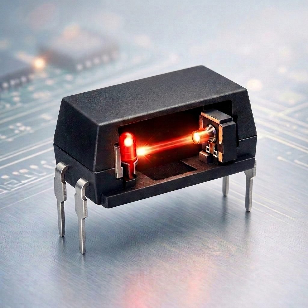
Optocoupler
Contents List
- Introduction
- What Is an Optocoupler?
- How Does an Optocoupler Work?
- Internal Structure of an Optocoupler
- Optocoupler Package Types and Forms
- Important Optocoupler Specifications
- Main Types of Optocouplers
- Optocoupler Applications
- Advantages and Limitations of Optocouplers
- Detailed Circuit Schematic and Connections
- Practical Optocoupler Circuit
- How the Practical Circuit Works?
- Understanding Current Transfer Ratio (CTR)
- How to Calculate the Input Resistor?
- Choosing the Output Pull-Up Resistor
- Differences Between Optocouplers, Relays, and Digital Isolators
- Common Optocoupler Design Mistakes
- Safety Considerations
- Frequently Asked Questions
- Conclusion
Reading Time is 20 minute
1- Introduction
An Optocoupler is an electronic component that transfers a signal between two electrically isolated circuits using light.
It is also commonly called a photocoupler, opto-isolator, or optical isolator. The basic principle is the same: an input signal drives a light-emitting device, and the light is detected by a device on the output side.
The most important characteristic of an optocoupler is the electrical isolation between its input and output sides. There is no normal conductive electrical connection between the two sides. Instead, information crosses the isolation barrier through light.
This makes optocouplers useful in power supplies, PLC interfaces, industrial control systems, communication interfaces, microcontroller circuits, feedback circuits, and many other applications where electrical isolation is required.
Optocouplers are particularly interesting because the same basic concept is available in many different forms, including phototransistor, photodiode, logic-output, TRIAC/thyristor, and photorelay devices. Toshiba’s technical documentation categorizes photocouplers according to their output structures and also provides separate guidance on their packages and applications.
This article explains optocouplers from the basic operating principle through practical circuit design. It is intended to be useful to beginners and hobbyists while also providing the important electrical and design considerations required by electronics engineers.
2- What Is an Optocoupler?
An Optocoupler is a semiconductor device that transfers an electrical signal from one circuit to another through an optical isolation barrier.
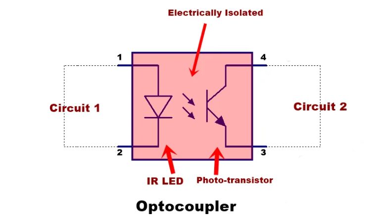
A common phototransistor optocoupler contains two main elements:
- An infrared LED on the input side.
- A phototransistor on the output side.
The input LED is electrically connected only to the input circuit.
The phototransistor is electrically connected only to the output circuit.
The two sides communicate through light.
This arrangement allows a signal to cross between circuits without creating a direct conductive path between their grounds.
Why Is Electrical Isolation Important?
Consider a system containing a low-voltage microcontroller and another circuit operating at a different voltage or ground potential.
If the two circuits are connected directly, unwanted current can flow between them. Depending on the application, this can cause ground-loop problems, electrical noise, malfunction, or even damage.
An optocoupler provides an isolation barrier between the two circuit domains.
The control circuit drives the LED, while the output circuit responds to the light produced by that LED.
The signal is therefore transferred without directly connecting the two electrical domains.
3- How Does an Optocoupler Work?
The operation of a basic phototransistor optocoupler can be understood in four steps:
- An input voltage is applied to the internal LED.
- Current flows through the LED.
- The LED emits infrared light across the internal isolation barrier.
- The phototransistor responds to the light and conducts current on the output side.
When the input LED is turned off, the amount of emitted light decreases and the phototransistor turns off.
The input and output circuits therefore communicate through light rather than through a conductive electrical connection.
A Simple Way to Understand the Principle
Imagine a small flashlight shining toward a light-sensitive switch.
The flashlight represents the input LED.
The light represents the optical signal.
The light-sensitive switch represents the output device.
There is no electrical wire connecting the flashlight to the switch, but the switch can still respond to the flashlight.
An optocoupler performs a similar function inside a semiconductor package.
4- Internal Structure of an Optocoupler
A typical phototransistor optocoupler contains an infrared LED and a phototransistor separated by an electrical isolation barrier.
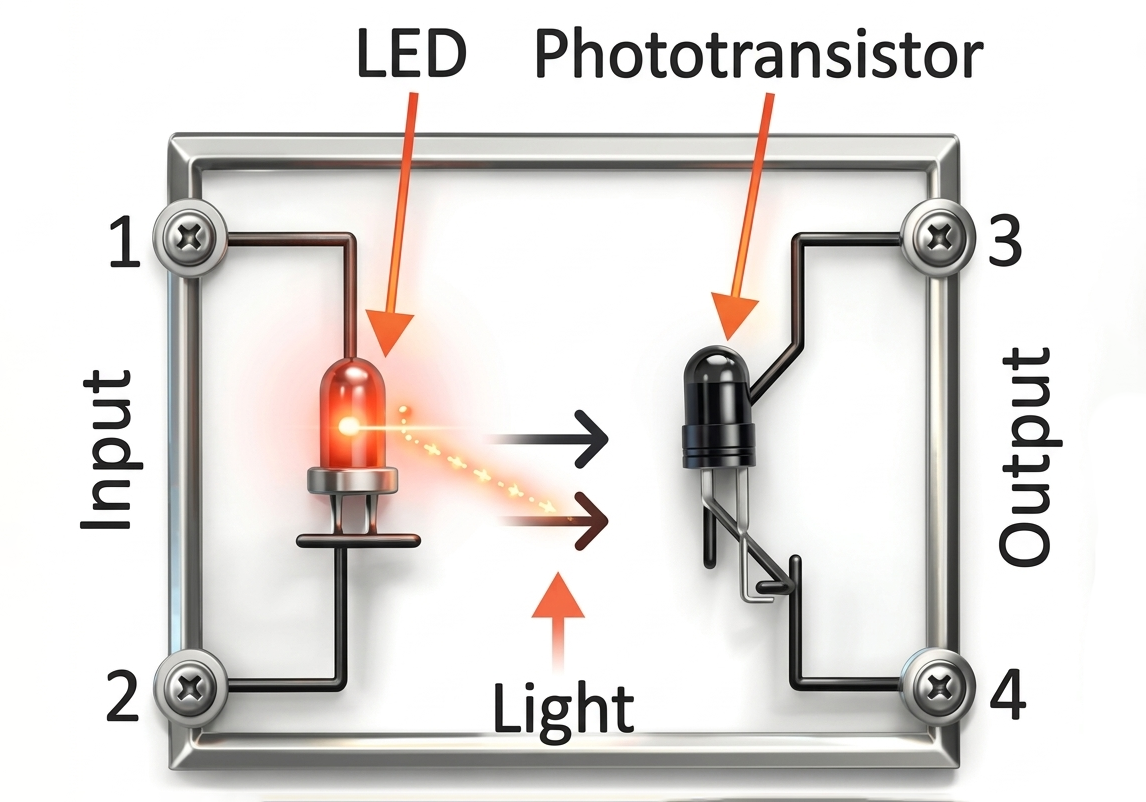
A simplified representation is:
             INPUT SIDE                    OUTPUT SIDE

           LED / Emitter                 Phototransistor

              Anode                           Collector
                |                                |
                |                                |
             +--|>|--+       Light            +---C
             |       |  ==================>   |
             |       |                        |
           Input     |                  Output transistor
           circuit   |                        |
             |       |                        +---E
             |       |
           Cathode

             GND1                              GND2

                    <--- Electrical Isolation --->
The input LED converts electrical current into light.
The photodetector converts the received light back into an electrical response.
The isolation barrier prevents normal current from flowing directly between the input and output circuits.
5- Optocoupler Package Types and Forms
Optocouplers are available in several physical package styles.
The package is not simply a mechanical enclosure. It can affect PCB footprint, assembly method, creepage, clearance, isolation capability, and the overall suitability of the device for a particular application.
Through-Hole DIP Packages
Traditional DIP optocouplers are designed for through-hole PCB assembly.
They are popular in:
- Educational projects
- Hobbyist circuits
- Prototypes
- Through-hole PCBs
- Manual assembly
The relatively large physical size can make the component easy to handle and inspect.
A common single-channel DIP optocoupler uses four pins, although the exact pin arrangement depends on the specific device.
The designer should always check the manufacturer’s datasheet before making the connections.
Surface-Mount SO and SOP Packages
Surface-mount optocouplers are available in small-outline package families such as SO and SOP.
They are suitable for:
- Compact PCBs
- Automated assembly
- High component density
- Commercial electronics
The practical TLP291(SE) used in this article is an example.
Toshiba specifies the TLP291(SE) as a 4-pin SO4 surface-mount package, measuring approximately 2.6 mm × 7.0 mm × 2.1 mm.
Wide-Body Packages
Some optocouplers use wider packages to provide increased spacing between the input and output sides.
The larger separation can help achieve greater creepage and clearance distances.
These packages are particularly useful when the application requires higher isolation performance or specific safety requirements.
However, package width alone does not determine whether a device is suitable for a particular safety application.
The designer must examine the manufacturer’s specified isolation voltage, working voltage, creepage, clearance, insulation characteristics, and applicable certifications.
Multi-Channel Packages
An optocoupler package does not necessarily contain only one isolated channel.
Some devices integrate multiple independent optocoupler channels into one package.
For example, a multi-channel device can provide two or four isolated signal paths while occupying less PCB area than several individual components.
This can be useful in:
- Industrial I/O
- Digital interfaces
- Microcontroller isolation
- Control systems
- Communication interfaces
The isolation between channels and the electrical characteristics of each channel must be checked in the manufacturer’s datasheet.
High-Isolation Packages
Some optocouplers are designed for applications requiring high isolation capability.
Such devices can use package structures and insulation systems designed to provide larger creepage and clearance distances.
When evaluating a high-isolation package, the designer should consider:
- Isolation test voltage
- Working voltage
- Creepage distance
- Clearance distance
- Insulation system
- Surge voltage
- Safety certification
An important point is that isolation test voltage is not automatically the same as continuous working voltage.
For example, the TLP291(SE) specifies a minimum isolation voltage of 3750 Vrms under the manufacturer’s defined test conditions. This should not be interpreted as a statement that 3750 Vrms can be continuously applied during normal operation.
Through-Hole vs. Surface-Mount Packages
| Characteristic | Through-Hole | Surface-Mount |
|---|---|---|
| PCB mounting | Leads pass through PCB holes | Mounted directly on PCB pads |
| Manual assembly | Very convenient | Requires more care |
| Automated assembly | Less suitable | Excellent |
| PCB area | Usually larger | Usually smaller |
| Prototyping | Very convenient | Convenient with suitable tools |
| Component density | Lower | Higher |
| Typical applications | Education, prototypes, through-hole boards | Commercial and compact PCBs |
- Neither package style is universally better.
- For hobby projects and educational experiments, a through-hole package can be easier to handle.
- For compact commercial products, a surface-mount package is often more appropriate.
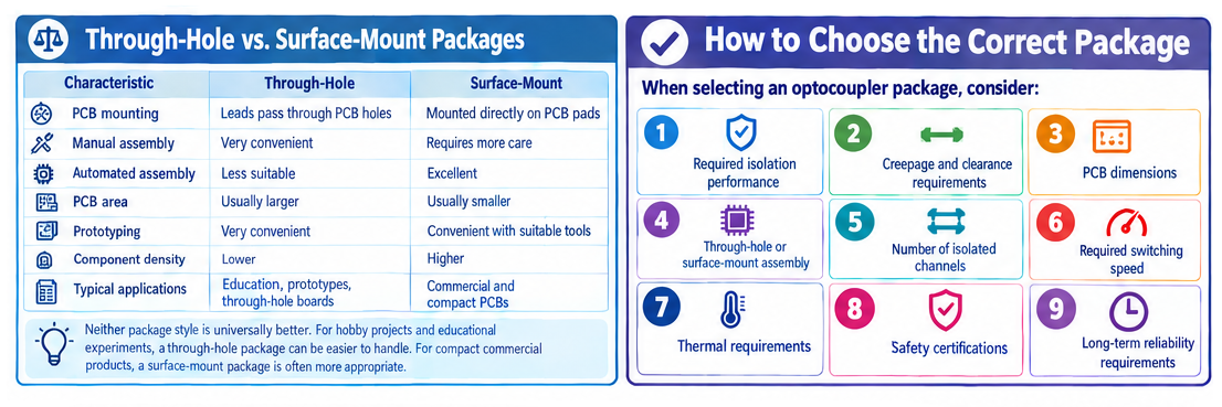
How to Choose the Correct Package
When selecting an optocoupler package, consider:
- Required isolation performance.
- Creepage and clearance requirements.
- PCB dimensions.
- Through-hole or surface-mount assembly.
- Number of isolated channels.
- Required switching speed.
- Thermal requirements.
- Safety certifications.
- Long-term reliability requirements.
The package should therefore be considered part of the electrical and safety design rather than merely a mechanical choice.
6- Important Optocoupler Specifications
Selecting an optocoupler requires more than checking its nominal isolation voltage.
The following parameters are particularly important.
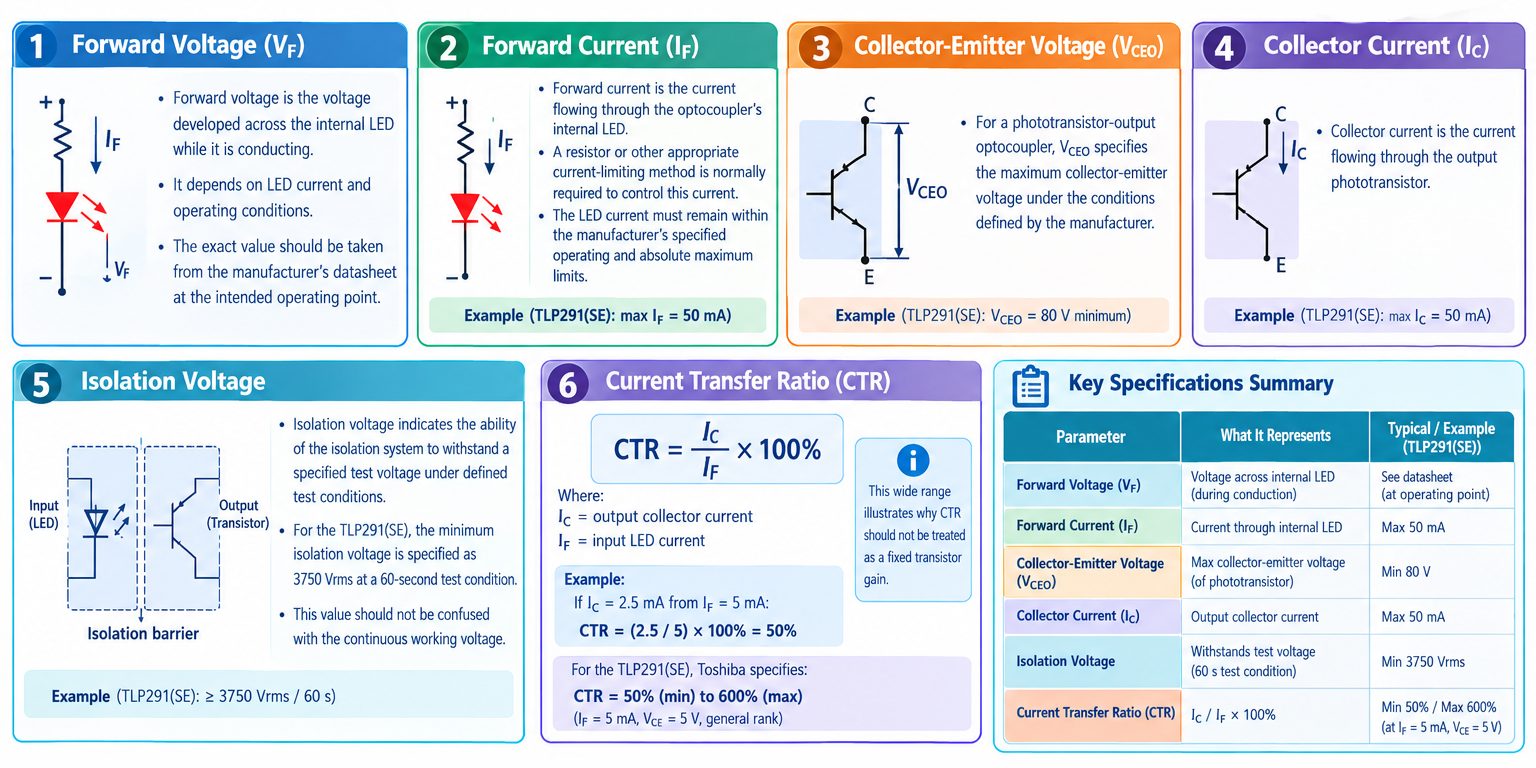
Forward Voltage (VF)
Forward voltage is the voltage developed across the internal LED while it is conducting.
It depends on LED current and operating conditions.
The exact value should be taken from the manufacturer’s datasheet at the intended operating point.
Forward Current (IF)
Forward current is the current flowing through the optocoupler’s internal LED.
A resistor or other appropriate current-limiting method is normally required to control this current.
The LED current must remain within the manufacturer’s specified operating and absolute maximum limits.
For the TLP291(SE), Toshiba specifies a maximum forward current of 50 mA.
Collector-Emitter Voltage (VCEO)
For a phototransistor-output optocoupler, VCEO specifies the maximum collector-emitter voltage under the conditions defined by the manufacturer.
For the TLP291(SE), VCEO is specified as 80 V minimum.
Collector Current (IC)
Collector current is the current flowing through the output phototransistor.
The TLP291(SE) specifies a maximum collector current of 50 mA.
Isolation Voltage
Isolation voltage indicates the ability of the isolation system to withstand a specified test voltage under defined test conditions.
For the TLP291(SE), the minimum isolation voltage is specified as 3750 Vrms at a 60-second test condition.
Again, this value should not be confused with the continuous working voltage.
Current Transfer Ratio (CTR)
CTR is one of the most important specifications of a phototransistor optocoupler.
It is commonly expressed as:
CTR = IC / IF × 100%
Where:
- IC = output collector current
- IF = input LED current
For example, if an optocoupler produces 2.5 mA collector current from 5 mA LED current:
CTR = (2.5 / 5) × 100%
CTR = 50%
For the TLP291(SE), Toshiba specifies a minimum CTR of 50% and a maximum of 600% under the stated test conditions of IF = 5 mA and VCE = 5 V for the general rank.
This wide range illustrates why CTR should not be treated as a fixed transistor gain.
7- Main Types of Optocouplers
The output device is one of the main characteristics used to classify optocouplers.
Toshiba identifies several major output types, including phototransistor, IC/logic, TRIAC/thyristor, and MOSFET-output photorelay devices.
Phototransistor Optocoupler
A phototransistor optocoupler uses a phototransistor as the output device.
This is one of the most common types and is particularly useful for general-purpose signal isolation.
The TLP291(SE) used in the practical circuit in this article is a phototransistor-output photocoupler.
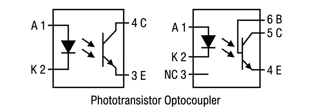
Phototransistor optocouplers are commonly used for:
- Digital signal isolation
- Feedback circuits
- PLC interfaces
- Microcontroller interfaces
- General-purpose switching
Their main design considerations include CTR, LED current, output load, temperature, and switching speed.
Photodiode and High-Speed Optocouplers
Photodiode-based optocouplers can provide faster response than basic phototransistor devices.
They are useful when higher switching speed or signal bandwidth is required.
Some devices combine a photodiode with additional integrated circuitry to produce a logic-level output.
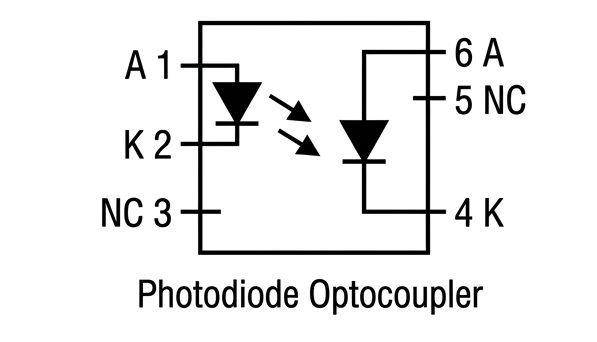
For high-speed digital applications, the designer should check the actual propagation delay, rise time, fall time, maximum data rate, and other dynamic specifications instead of selecting a device based only on its isolation rating.
Photo-SCR Optocoupler

The photo-SCR optocoupler uses a light-activated Silicon Controlled Rectifier (SCR) as its output device. When the internal LED emits light, it triggers the SCR into conduction. One key characteristic of this type is its ability to handle relatively high voltage and current levels. It can operate in both AC and DC circuits and may remain latched in the ON state after being triggered until the current falls below the holding level. Because of these features, photo-SCR optocouplers are often used in industrial power control systems and high-voltage switching applications.
Darlington Optocoupler
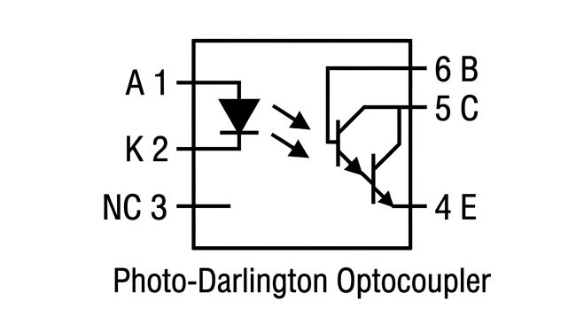
A Darlington optocoupler uses two transistors connected as a Darlington pair at the output stage. This configuration provides much higher current gain compared to a single phototransistor, meaning a very small input current can control a significantly larger output current. As a result, it is more sensitive and requires less LED drive current. However, the trade-off is slower switching speed due to the increased gain structure. Darlington optocouplers are commonly used when strong amplification is needed but high-speed switching is not critical.
TRIAC and Thyristor-Output Optocouplers
These optocouplers are designed primarily for AC switching and control.
A phototriac or phot thyristor is used on the output side.
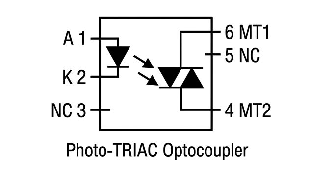
They can be used to isolate a low-voltage control circuit from an AC switching circuit.
The exact device must be selected according to whether zero-cross switching, random-phase switching, load current, voltage, and other requirements are important.
8- Optocoupler Applications
Optocouplers are used in a wide range of electronic systems.
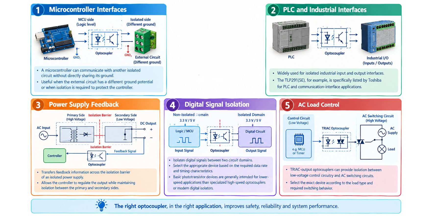
Microcontroller Interfaces
A microcontroller can communicate with another isolated circuit without directly sharing its ground.
This can be useful when the external circuit has a different ground potential or when isolation is required to protect the controller.
PLC and Industrial Interfaces
Optocouplers are widely used for isolated industrial input and output interfaces.
Power Supply Feedback
Optocouplers can transfer feedback information across the isolation barrier of an isolated power supply.
The controller can therefore regulate the output while maintaining isolation between the primary and secondary sides.
Digital Signal Isolation
Optocouplers can isolate digital signals between two circuit domains.
The appropriate device must be selected according to the required data rate and timing characteristics.
Basic phototransistor devices are generally intended for lower-speed applications than specialized high-speed optocouplers or modern digital isolators.
AC Load Control
TRIAC-output optocouplers can provide isolation between low-voltage control circuitry and AC switching circuits.
The exact device must be selected according to the load type and required switching behavior.
9- Advantages and Limitations of Optocouplers
Advantages
- Provides galvanic isolation.
- Does not require a direct conductive connection between the two isolated sides.
- Available in many output configurations.
- Suitable for a wide range of isolation applications.
- Available in compact surface-mount packages.
- Can be economical for simple isolated signal paths.
- Useful in power supplies, PLC interfaces, and general-purpose signal isolation.
Limitations
Conventional optocouplers also have characteristics that must be considered during design.
These include:
- CTR variation between devices.
- CTR dependence on operating conditions.
- CTR degradation with aging.
- LED input-current requirements.
- Limited speed for many general-purpose phototransistor devices.
- Additional external components such as LED resistors and pull-up resistors.
- Temperature dependence.
Texas Instruments specifically identifies CTR variation and aging as important considerations when comparing traditional optocouplers with digital isolators.
Therefore, an optocoupler should not automatically be selected simply because it provides electrical isolation.
The designer should select the isolation technology according to the complete system requirements.
10- Detailed Circuit Schematic and Connections
The basic circuit can be represented as follows:
                 INPUT SIDE                       OUTPUT SIDE
              ISOLATED DOMAIN                   ISOLATED DOMAIN

                  +5V                               +5V
                   |                                 |
                   |                                R2
                  R1                               4.7kΩ
                750Ω                                 |
                   |                                 |
                   |                                 +------ OUTPUT
                   |                                 |
                Pin 1                            Pin 4
                 Anode                           Collector
                   |                                 |
                ┌──┴──────────────────────────────┐  |
                │                                  │  |
                │          TLP291(SE)              │  |
                │                                  │  |
                │        LED          Light        │  |
                │       ────       ========>       │  |
                │                                  │  |
                │                    Phototransistor
                │                                  │  |
                └── Pin 2                 Pin 3 ───┘
                  Cathode                    Emitter
                     |                         |
                    GND1                      GND2


                NO ELECTRICAL CONNECTION
                  BETWEEN GND1 AND GND2

                   <--- ISOLATION BARRIER --->
Input-Side Connections
Connect the input side as follows:
- Connect the positive 5 V input supply to R1.
- Connect the other side of R1 to pin 1, the LED anode.
- Connect pin 2, the LED cathode, to GND1.
The input current path is therefore:
5 V → R1 → TLP291(SE) LED → GND1
When the LED conducts, it emits infrared light.
Output-Side Connections
Connect the output side as follows:
- Connect VCC2 to one side of R2.
- Connect the other side of R2 to pin 4, the collector.
- Connect pin 3, the emitter, to GND2.
- Take the output signal from the junction of R2 and pin 4.
This creates an open-collector-style output arrangement.
The Most Important Connection
Do not connect GND1 and GND2 if the purpose of the circuit is to demonstrate galvanic isolation.
The signal crosses from the input domain to the output domain through light.
11- Practical Optocoupler Circuit
To demonstrate the operating principle without introducing mains voltage, the practical circuit uses two isolated 5 V domains.
The input side contains:
- TLP291(SE)
- R1 = 750 Ω
- 5 V input supply
- GND1
The output side contains:
- Separate 5 V supply
- R2 = 4.7 kΩ
- GND2
- Output signal
The two grounds are intentionally not connected.
This allows the circuit to demonstrate the isolation principle using low-voltage supplies.
12- How the Practical Optocoupler Circuit Works?
When the input LED is OFF, the phototransistor is substantially OFF.
R2 then pulls the output toward VCC2.
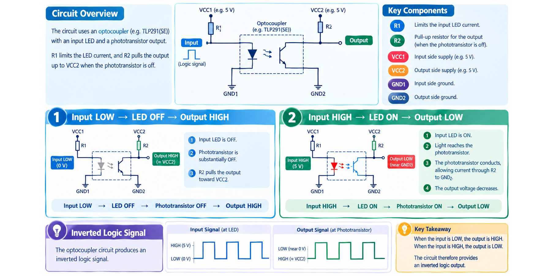
Therefore:
Input LOW → LED OFF → Phototransistor OFF → Output HIGH
When the input LED is ON, light reaches the phototransistor.
The phototransistor conducts and allows current to flow through R2 toward GND2.
The output voltage therefore decreases.
Therefore:
Input HIGH → LED ON → Phototransistor ON → Output LOW
The circuit consequently produces an inverted logic signal.
13- Understanding Current Transfer Ratio (CTR)
CTR describes how effectively the input LED current is transferred into output collector current.
For example:
IF = 5 mA
CTR = 50%
Then the corresponding minimum collector current under the specified test conditions is approximately:
IC = IF × CTR
IC = 5 mA × 0.50
IC = 2.5 mA
However, this calculation should not be interpreted as a universal operating point.
CTR depends on operating conditions, temperature, LED current, device variation, and aging.
Texas Instruments also highlights CTR variation and aging as important considerations when comparing traditional optocouplers with digital isolators.
For reliable circuit design, the designer should use the appropriate minimum guaranteed CTR rather than simply using a typical value.
14- How to Calculate the Input Resistor?
The input LED normally requires a current-limiting resistor.
The basic equation is:
RIN = (VIN − VF) / IF
Where:
- RIN = input resistor
- VIN = input voltage
- VF = LED forward voltage
- IF = desired LED current
Toshiba provides similar design guidance for determining the input current and resistor of a photocoupler.
Example With a 5 V Input
For an illustrative design, assume:
VIN = 5 V
VF ≈ 1.25 V
IF = 5 mA
Then:
RIN = (5 − 1.25) / 0.005
RIN = 750 Ω
Therefore, 750 Ω is a convenient nominal resistor value for this example.
However, the actual forward-voltage value and required LED current should be checked against the exact TLP291(SE) datasheet and the desired circuit operating point before using the design in a production application.
15- Choosing the Output Pull-Up Resistor
The output resistor determines the current that the phototransistor must sink when it is ON.
For example:
VCC2 = 5 V
R2 = 4.7 kΩ
The approximate current when the output is pulled close to ground is:
I = V / R
I = 5 / 4700
I ≈ 1.06 mA
This current is well below the TLP291(SE)’s 50 mA maximum collector-current rating.
However, the output should not be designed only from the maximum collector-current rating.
The designer must also verify that the available collector current is sufficient for the required logic-low voltage under the worst-case CTR and operating conditions.
The value of the pull-up resistor also affects switching speed.
A larger resistance reduces current consumption but can increase the time required for the output capacitance to charge and discharge.
This becomes especially important in higher-speed applications. Texas Instruments demonstrates that the pull-up resistor and optocoupler output characteristics can significantly affect the achievable timing performance.
16- Differences Between Optocouplers, Relays, and Digital Isolators
Optocouplers, relays, and digital isolators can all provide isolation between circuit domains, but they use fundamentally different technologies.
An optocoupler uses optical coupling.
A relay uses electromagnetic coupling and mechanical contacts.
A digital isolator uses semiconductor-based isolation techniques, commonly capacitive or magnetic coupling depending on the device architecture.
The choice between them depends on factors such as signal speed, output power, lifetime, power consumption, physical size, timing requirements, and the type of load being controlled.
Comparison of the Three Technologies
| Feature | Optocoupler | Relay | Digital Isolator |
|---|---|---|---|
| Isolation method | Optical | Electromagnetic | Semiconductor-based coupling |
| Main structure | LED + photodetector | Coil + mechanical contacts | Integrated semiconductor circuits |
| Moving parts | No | Yes | No |
| Direct conductive connection between sides | No | No | No |
| Typical output | Phototransistor, photodiode, TRIAC, logic, MOSFET | Mechanical contacts | Digital logic output |
| Switching speed | Depends strongly on type | Generally slow | Generally high |
| Contact bounce | No | Yes | No |
| Mechanical wear | No | Yes | No |
| Output load capability | Usually limited compared with power relays | Can be high, depending on relay | Intended primarily for electronic loads |
| Input power | LED current required | Coil power required | Usually low digital input current |
| Additional components | Often required | Driver may be required | Usually fewer external components |
| Digital timing | Can vary with CTR and load | Not suitable for high-speed digital signaling | Generally precise and fast |
| High-speed communication | Limited for many general-purpose types | Generally unsuitable | Excellent |
| AC load switching | Possible with suitable output type | Very suitable for many loads | Generally not direct load switching |
| Analog/feedback applications | Common | Possible in some systems | Possible with suitable device |
| Physical size | Small | Usually larger | Small |
| Mechanical lifetime | No contact wear | Limited by mechanical life | Generally high |
| Typical applications | Signal isolation, feedback, PLC interfaces | Load switching and power control | High-speed digital signal isolation |
| Main advantage | Simple and versatile isolation | Can switch substantial electrical loads through contacts | High speed and predictable digital performance |
| Main limitation | CTR variation and speed limitations | Mechanical wear and slow switching | Primarily designed for electronic signal isolation |
Which Technology Should You Choose?
A simple decision process is:
- Choose an optocoupler when you need general-purpose signal isolation and the required speed and transfer characteristics are compatible with the device.
- Choose a relay when the isolated output needs to switch a load through electrical contacts or when normally open/normally closed contacts are required.
- Choose a digital isolator when high-speed digital communication, predictable timing, low power consumption, or multiple isolated digital channels are important.
There is no universally superior isolation technology.
The correct choice depends on the electrical, mechanical, timing, safety, and system requirements of the application.
17- Common Optocoupler Design Mistakes
Connecting the Two Grounds
If GND1 and GND2 are connected together, the intended galvanic isolation between the two circuit domains may be defeated.
Always identify the input-side and output-side domains clearly.
Omitting the Input Current-Limiting Resistor
The internal LED requires controlled current.
A suitable resistor is normally required to prevent excessive LED current.
Designing With Typical CTR Only
A typical CTR value should not be treated as a guaranteed value.
For reliable designs, consider the minimum CTR under the actual operating conditions.
Using an Excessive LED Current
Increasing LED current is not always the correct way to improve performance.
The LED has maximum current and power limitations.
Higher current can also affect device lifetime and system power consumption.
Ignoring Switching Speed
A circuit that works at a few hertz may not work correctly at a much higher frequency.
For PWM, UART, SPI, or other digital signals, check the actual timing specifications.
Choosing the Pull-Up Resistor Without Considering Timing
A pull-up resistor that is too large can reduce current but may slow the output transition.
A resistor that is too small increases current consumption.
The correct value must balance logic levels, CTR, load, power consumption, and timing.
Treating Isolation Voltage as Continuous Working Voltage
A test voltage specification is not automatically a continuous operating-voltage specification.
The complete insulation system, package, PCB layout, and applicable safety requirements must be considered.
18- Safety Considerations
Optocouplers are often used in circuits containing hazardous voltages, but an optocoupler alone does not make a circuit safe.
When designing an isolation barrier, consider:
- Creepage distance
- Clearance distance
- Working voltage
- Surge voltage
- Insulation type
- Pollution degree
- PCB layout
- Component certification
- System-level safety standards
- Enclosure and touch protection
The TLP291(SE) has safety approvals listed by Toshiba, including UL 1577, cUL, EN 60747-5-5, EN IEC 62368-1, and CQC approvals for the specified device/configuration.
However, component certification does not automatically certify the complete PCB or finished product.
For beginners and hobbyists, the practical circuit presented in this article should be implemented using low-voltage isolated supplies rather than directly connecting the circuit to mains voltage.
19- Frequently Asked Questions
What is an optocoupler?
An optocoupler is a device that transfers a signal between two electrically isolated circuits using light.
Is an optocoupler the same as an opto-isolator?
In common electronics terminology, yes. Optocoupler, photocoupler, opto-isolator, and optical isolator are commonly used to describe devices that transfer information across an electrical isolation barrier using optical coupling.
Why are optocouplers used?
They are used to transfer signals while maintaining electrical isolation between two circuit domains.
Typical applications include power supplies, PLC interfaces, industrial controls, digital signal isolation, and feedback circuits.
Does an optocoupler connect the two grounds?
No.
If galvanic isolation is required, the input and output grounds should remain electrically separated.
Why does an optocoupler need a resistor?
The resistor limits the current through the internal LED.
The required value depends on the input voltage, LED forward voltage, desired LED current, and device specifications.
What is CTR?
CTR stands for Current Transfer Ratio.
It describes the relationship between output collector current and input LED current:
CTR = IC / IF × 100%
CTR is particularly important for phototransistor-output optocouplers.
Is higher CTR always better?
No.
The appropriate CTR depends on the circuit.
A high CTR may allow lower LED current, but other parameters such as switching speed, temperature characteristics, aging, and device variation must also be considered.
Can an optocoupler be used for AC?
Some optocouplers are specifically designed for AC switching.
TRIAC- and thyristor-output optocouplers are common examples.
A standard phototransistor optocoupler should not automatically be assumed to be suitable for an AC-load application.
Can an optocoupler protect a microcontroller from high voltage?
It can provide an isolation barrier between the microcontroller and another circuit.
However, system-level protection also depends on PCB creepage and clearance, insulation, surge protection, component ratings, and the applicable safety requirements.
What is the difference between an optocoupler and a relay?
An optocoupler is a semiconductor device that transfers a signal optically.
A relay uses an electromagnetic mechanism and mechanical contacts.
An optocoupler is generally more suitable for electronic signal isolation, while a relay can be useful when the isolated output must directly switch a load through contacts.
What is the difference between an optocoupler and a digital isolator?
An optocoupler normally uses an LED and optical detector.
A digital isolator uses semiconductor-based coupling and integrated digital circuitry.
Digital isolators are generally better suited to high-speed digital communication and applications requiring predictable timing.
Why does the output of the practical circuit become inverted?
The phototransistor and pull-up resistor form an inverting arrangement.
When the input LED is OFF, the phototransistor is OFF and the pull-up resistor drives the output HIGH.
When the input LED is ON, the phototransistor conducts and pulls the output LOW.
Can I replace the TLP291(SE) with a PC817?
Not automatically.
Although both can be used as phototransistor optocouplers, the exact electrical specifications, CTR range, switching characteristics, package, pinout, isolation rating, and safety certifications must be compared.
A replacement should be selected using the exact manufacturer’s datasheet rather than by assuming that all four-pin optocouplers are interchangeable.
20- Conclusion
An optocoupler is a fundamental isolation component that allows a signal to cross between two electrically isolated circuits without creating a direct conductive connection.
The basic operating principle is simple: an input LED generates light, and an output device detects that light.
However, designing a reliable optocoupler circuit requires more than understanding this basic principle.
Important parameters include LED forward current, forward voltage, CTR, collector current, collector-emitter voltage, isolation voltage, switching speed, temperature, aging, creepage, clearance, and package characteristics.
The article also demonstrates why package selection matters. Through-hole, surface-mount, wide-body, and multi-channel packages can have very different implications for PCB layout, assembly, isolation distance, and system requirements.
Finally, optocouplers should be considered alongside other isolation technologies.
A relay may be the better choice when mechanical contacts are required to switch a load.
A digital isolator may be the better choice for high-speed digital communication and applications requiring predictable timing and low input power.
An optocoupler remains an excellent choice for many general-purpose isolation applications, particularly when a simple, compact, and economical isolation solution is required.
المقحل الضوئي (Optocoupler)
قائمة المحتويات
- مقدمة
- ما هو المقحل الضوئي؟
- كيف يعمل المقحل الضوئي؟
- التركيب الداخلي للمقحل الضوئي
- أنواع وأشكال حزم المقحل الضوئي
- أهم مواصفات المقحل الضوئي
- الأنواع الرئيسية للمقحلات الضوئية
- تطبيقات المقحلات الضوئية
- مزايا المقحلات الضوئية وحدودها
- المخطط التفصيلي للدائرة والتوصيلات
- دائرة المقحل الضوئي العملية
- كيف تعمل الدائرة العملية؟
- فهم نسبة نقل التيار (CTR)
- كيف نحسب مقاومة الدخل؟
- اختيار مقاومة السحب لأعلى عند الخرج
- الفروق بين المقحلات الضوئية والمرحلات والعوازل الرقمية
- أخطاء التصميم الشائعة في دوائر المقحل الضوئي
- اعتبارات السلامة
- الأسئلة الشائعة
- الخلاصة
زمن القراءة حوالي : 20 دقيقة
1- مقدمة
المقحل الضوئي هو مكوّن إلكتروني ينقل إشارة بين دائرتين معزولتين كهربائياً باستخدام الضوء.
ويُعرف أيضاً بأسماء مثل Photocoupler وOpto-Isolator وOptical Isolator. والفكرة الأساسية واحدة: تقوم إشارة الدخل بتشغيل عنصر باعث للضوء، ثم يلتقط الضوء عنصر موجود في جهة الخرج.
أهم ما يميز المقحل الضوئي هو العزل الكهربائي بين الدخل والخرج. فلا يوجد مسار كهربائي توصيلي عادي يربط الجانبين، بل تنتقل المعلومات عبر حاجز العزل بواسطة الضوء.
ولهذا السبب يُستخدم في مزودات الطاقة، وواجهات PLC، وأنظمة التحكم الصناعية، وواجهات الاتصالات، ودوائر المتحكمات الدقيقة، ودوائر التغذية الراجعة، وغيرها من التطبيقات التي تحتاج إلى عزل كهربائي.
وتوجد هذه الفكرة في أشكال متعددة، منها المقحلات الضوئية ذات خرج الترانزستور الضوئي، والخرج بالدايود الضوئي، والخرج المنطقي، وTRIAC/Thyristor، والـPhotorelay.
يشرح هذا المقال المقحل الضوئي بدءاً من مبدأ عمله الأساسي وصولاً إلى تصميم دائرة عملية. وهو مناسب للمبتدئين والهواة، مع تضمين النقاط الكهربائية والتصميمية المهمة التي يحتاج إليها مهندس الإلكترونيات.
وفي المثال العملي سنستخدم المكوّن المحدد Toshiba TLP291(SE) بدلاً من الإشارة إلى مقحل ضوئي غير محدد، حتى تكون الحسابات والتوصيلات ومعلومات الحزمة والمواصفات الكهربائية مرتبطة مباشرة ببيانات الشركة المصنعة.
2- ما هو المقحل الضوئي؟
المقحل الضوئي هو عنصر شبه موصل ينقل إشارة كهربائية من دائرة إلى أخرى عبر حاجز عزل بصري.
يحتوي المقحل الضوئي الشائع ذو الخرج بالترانزستور الضوئي على عنصرين رئيسيين:
- LED يعمل بالأشعة تحت الحمراء في جهة الدخل.
- ترانزستور ضوئي في جهة الخرج.
يتصل LED الداخلي كهربائياً بدائرة الدخل فقط، بينما يتصل الترانزستور الضوئي كهربائياً بدائرة الخرج فقط.
ويتم التواصل بين الجانبين بواسطة الضوء. ويسمح هذا الترتيب بانتقال الإشارة بين الدائرتين دون إنشاء مسار توصيلي مباشر بين أرضيهما.
لماذا يُعد العزل الكهربائي مهماً؟
تخيل نظاماً يحتوي على متحكم دقيق منخفض الجهد ودائرة أخرى تعمل بجهد مختلف أو عند جهد أرضي مختلف.
إذا تم توصيل الدائرتين مباشرة، فقد يمر تيار غير مرغوب فيه بينهما. ووفقاً للتطبيق، قد يؤدي ذلك إلى مشاكل حلقات الأرضي، أو الضوضاء الكهربائية، أو حدوث خلل في التشغيل، أو حتى تلف بعض المكونات.
يوفر المقحل الضوئي حاجز عزل بين نطاقي الدائرة. تقود دائرة التحكم الـLED، بينما تستجيب دائرة الخرج للضوء الصادر عنه.
وبذلك تنتقل الإشارة دون توصيل المجالين الكهربائيين ببعضهما مباشرة.
3- كيف يعمل المقحل الضوئي؟
يمكن فهم عمل المقحل الضوئي ذي الترانزستور الضوئي من خلال أربع خطوات:
- يتم تطبيق جهد الدخل على الـLED الداخلي.
- يمر التيار عبر الـLED.
- يبعث الـLED ضوءاً تحت أحمر عبر حاجز العزل الداخلي.
- يستجيب الترانزستور الضوئي للضوء ويمرر التيار في جهة الخرج.
عندما ينطفئ LED الدخل، تقل كمية الضوء المنبعثة، فينطفئ الترانزستور الضوئي بدوره.
وبالتالي تتواصل دائرتا الدخل والخرج بواسطة الضوء بدلاً من وجود اتصال كهربائي توصيلي مباشر بينهما.

طريقة بسيطة لفهم المبدأ
تخيل مصباحاً صغيراً يضيء باتجاه مفتاح حساس للضوء.
يمثل المصباح الـLED الموجود في جهة الدخل، ويمثل الضوء الإشارة الضوئية، بينما يمثل المفتاح الحساس للضوء عنصر الخرج.
لا يوجد سلك كهربائي يربط المصباح بالمفتاح، ومع ذلك يستطيع المفتاح الاستجابة لضوء المصباح.
يعمل المقحل الضوئي وفق فكرة مشابهة داخل حزمة شبه موصل صغيرة.
4- التركيب الداخلي للمقحل الضوئي
يحتوي المقحل الضوئي النموذجي ذو الخرج بالترانزستور الضوئي على LED يعمل بالأشعة تحت الحمراء وترانزستور ضوئي يفصل بينهما حاجز عزل كهربائي.
تمثيل مبسط للتركيب:
              جهة الدخل                    جهة الخرج

          LED / الباعث                 الترانزستور الضوئي

             Anode                         Collector
               |                              |
             +-|>|-+       Light           +---C
             |     |  ==================>   |
           دائرة   |                       ترانزستور الخرج
           الدخل   |                          |
             |     |                          +---E
             |     |
           Cathode

             GND1                            GND2

                 <--- حاجز العزل الكهربائي --->
يحوّل LED تيار الدخل الكهربائي إلى ضوء، بينما يحوّل الكاشف الضوئي الضوء المستلم إلى استجابة كهربائية.
ويمنع حاجز العزل مرور التيار العادي مباشرة بين دائرتي الدخل والخرج.
5- أنواع وأشكال حزم المقحل الضوئي
تتوفر المقحلات الضوئية بعدة أشكال فيزيائية للحزم. ولا تقتصر وظيفة الحزمة على كونها غلافاً ميكانيكياً؛ فهي تؤثر في مساحة تركيب المكوّن على PCB، وطريقة التجميع، ومسافات الزحف والخلوص، وقدرة العزل، ومدى ملاءمة المكوّن للتطبيق.
حزم DIP للتركيب عبر الثقوب
صُممت حزم DIP التقليدية للتركيب عبر الثقوب في لوحات الدوائر المطبوعة. وتنتشر في المشاريع التعليمية، ودوائر الهواة، والنماذج الأولية، واللوحات ذات المكونات Through-Hole، والتجميع اليدوي.
كما أن حجمها الفيزيائي الأكبر نسبياً يجعل التعامل معها وفحصها أسهل.
يستخدم المقحل الضوئي أحادي القناة الشائع أربعة أطراف، إلا أن ترتيب الأطراف يختلف حسب المكوّن، لذلك يجب دائماً الرجوع إلى ورقة بيانات الشركة المصنعة قبل التوصيل.
حزم SO وSOP للتركيب السطحي
تتوفر المقحلات الضوئية للتركيب السطحي ضمن عائلات حزم صغيرة مثل SO وSOP. وهي مناسبة للوحات المدمجة، والتجميع الآلي، والكثافة العالية للمكونات، والإلكترونيات التجارية.
المكوّن العملي المستخدم في هذا المقال، TLP291(SE)، مثال على ذلك. وتحدد Toshiba المكوّن TLP291(SE) على أنه حزمة SO4 ذات أربعة أطراف للتركيب السطحي، بأبعاد تقارب 2.6 مم × 7.0 مم × 2.1 مم.
الحزم العريضة
تستخدم بعض المقحلات الضوئية حزمًا أعرض لتوفير مسافة أكبر بين جانبي الدخل والخرج، وقد يساعد الفصل الأكبر في تحقيق مسافات زحف وخلوص أعلى.
وتفيد هذه الحزم عندما يتطلب التطبيق أداء عزل أعلى أو متطلبات سلامة محددة. لكن عرض الحزمة وحده لا يحدد صلاحية المكوّن لتطبيق سلامة معين؛ يجب فحص جهد العزل، وجهد التشغيل، ومسافات الزحف والخلوص، وخصائص العزل، والشهادات المعمول بها.
الحزم متعددة القنوات
لا يشترط أن تحتوي حزمة المقحل الضوئي على قناة معزولة واحدة فقط. تدمج بعض المكونات قناتين أو أربع قنوات مستقلة داخل الحزمة نفسها، مما يمكن أن يوفر عدة مسارات إشارات معزولة مع تقليل مساحة PCB مقارنة باستخدام عدة مكونات منفصلة.
ويجب التحقق من العزل بين القنوات والخصائص الكهربائية لكل قناة من ورقة بيانات الشركة المصنعة.
حزم العزل العالي
صُممت بعض المقحلات الضوئية للتطبيقات التي تتطلب قدرة عزل عالية، وقد تستخدم بنية للحزمة تسمح بمسافات زحف وخلوص أكبر.
عند تقييم حزمة عالية العزل، ينبغي النظر إلى جهد اختبار العزل، وجهد التشغيل، ومسافة الزحف، ومسافة الخلوص، ونظام العزل، وجهد الصدمة، وشهادة السلامة.
ومن النقاط المهمة أن جهد اختبار العزل ليس بالضرورة هو نفسه جهد التشغيل المستمر.
فعلى سبيل المثال، تحدد TLP291(SE) حداً أدنى لجهد العزل قدره 3750 Vrms وفق شروط الاختبار المحددة من الشركة المصنعة، ولا ينبغي تفسير ذلك على أنه إمكانية تطبيق 3750 Vrms بشكل مستمر أثناء التشغيل الطبيعي.
مقارنة الحزم Through-Hole وSurface-Mount
| الخاصية | Through-Hole | Surface-Mount |
|---|---|---|
| تركيب PCB | الأطراف تمر عبر ثقوب اللوحة | يثبت المكوّن مباشرة على وسادات PCB |
| التجميع اليدوي | سهل جداً | يتطلب عناية أكبر |
| التجميع الآلي | أقل ملاءمة | ممتاز |
| مساحة PCB | عادةً أكبر | عادةً أصغر |
| النماذج الأولية | مناسب جداً | مناسب مع الأدوات الملائمة |
| كثافة المكونات | أقل | أعلى |
| التطبيقات المعتادة | التعليم والنماذج الأولية واللوحات ذات الثقوب | اللوحات التجارية والمدمجة |
- لا توجد حزمة واحدة هي الأفضل دائماً.
- في مشاريع الهواة والتجارب التعليمية، قد تكون Through-Hole أسهل في التعامل.
- في المنتجات التجارية المدمجة، يكون Surface-Mount غالباً أكثر ملاءمة.
كيف تختار الحزمة الصحيحة؟
عند اختيار حزمة المقحل الضوئي، ضع في الاعتبار:
- أداء العزل المطلوب.
- متطلبات مسافتي الزحف والخلوص.
- أبعاد PCB.
- التركيب عبر الثقوب أو التركيب السطحي.
- عدد القنوات المعزولة المطلوبة.
- سرعة التبديل المطلوبة.
- المتطلبات الحرارية.
- شهادات السلامة.
- متطلبات الاعتمادية طويلة الأمد.
لذلك يجب النظر إلى الحزمة كجزء من التصميم الكهربائي وتصميم السلامة، وليس مجرد اختيار ميكانيكي.
6- أهم مواصفات المقحل الضوئي
اختيار المقحل الضوئي لا يعتمد فقط على فحص جهد العزل الاسمي، بل يجب النظر إلى مجموعة من المعلمات الكهربائية.
جهد التوصيل الأمامي (VF)
هو الجهد المتولد عبر LED الداخلي أثناء التوصيل، ويتغير حسب تيار LED وظروف التشغيل. يجب أخذ القيمة الدقيقة من ورقة بيانات الشركة المصنعة عند نقطة التشغيل المطلوبة.
التيار الأمامي (IF)
هو التيار المار عبر LED الداخلي للمقحل الضوئي. عادةً ما تكون هناك حاجة إلى مقاومة أو وسيلة مناسبة لتحديد التيار والتحكم فيه.
ويجب أن يبقى تيار LED ضمن حدود التشغيل والحدود القصوى المطلقة المحددة من الشركة المصنعة. بالنسبة إلى TLP291(SE)، تحدد Toshiba الحد الأقصى للتيار الأمامي عند 50 mA.
جهد المجمع-الباعث (VCEO)
في المقحل الضوئي ذي خرج الترانزستور الضوئي، يحدد VCEO أقصى جهد بين المجمع والباعث وفق شروط الشركة المصنعة. بالنسبة إلى TLP291(SE)، القيمة المحددة هي 80 V كحد أدنى.
تيار المجمع (IC)
هو التيار المار عبر ترانزستور الخرج الضوئي. وتحدد TLP291(SE) الحد الأقصى لتيار المجمع عند 50 mA.
جهد العزل
يشير جهد العزل إلى قدرة نظام العزل على تحمل جهد اختبار محدد وفق شروط اختبار معينة. بالنسبة إلى TLP291(SE)، الحد الأدنى المحدد هو 3750 Vrms عند اختبار لمدة 60 ثانية. ولا ينبغي الخلط بين هذه القيمة وجهد التشغيل المستمر.
نسبة نقل التيار (CTR)
تعد CTR من أهم مواصفات المقحل الضوئي ذي الخرج بالترانزستور الضوئي.
حيث:
- IC = تيار مجمع الخرج.
- IF = تيار LED في الدخل.
فإذا أنتج المقحل الضوئي تيار مجمع قدره 2.5 mA عند تيار LED مقداره 5 mA:
بالنسبة إلى TLP291(SE)، تحدد Toshiba قيمة CTR دنيا مقدارها 50% وقيمة قصوى مقدارها 600% وفق شروط الاختبار المذكورة، وهي IF = 5 mA وVCE = 5 V للرتبة العامة.
يوضح هذا المجال الواسع سبب عدم اعتبار CTR مكافئاً ثابتاً لكسب الترانزستور.
7- الأنواع الرئيسية للمقحلات الضوئية
يُعد عنصر الخرج من أهم الخصائص المستخدمة في تصنيف المقحلات الضوئية. وتشمل الأنواع الرئيسية الخرج بالترانزستور الضوئي، والخرج IC/Logic، وTRIAC/Thyristor، وMOSFET-output Photorelay.
المقحل الضوئي ذو الترانزستور الضوئي
يستخدم هذا النوع ترانزستوراً ضوئياً كعنصر خرج، وهو من أكثر الأنواع شيوعاً ومناسب بشكل خاص لعزل الإشارات للأغراض العامة.
المكوّن TLP291(SE) المستخدم في الدائرة العملية بهذا المقال هو مقحل ضوئي ذو خرج بالترانزستور الضوئي.
من استخداماته الشائعة:
- عزل الإشارات الرقمية.
- دوائر التغذية الراجعة.
- واجهات PLC.
- واجهات المتحكمات الدقيقة.
- التبديل للأغراض العامة.
ومن أهم اعتبارات التصميم: CTR، وتيار LED، وحمل الخرج، ودرجة الحرارة، وسرعة التبديل.
المقحلات الضوئية ذات الدايود الضوئي والأنواع عالية السرعة
يمكن للمقحلات الضوئية المعتمدة على الدايود الضوئي أن توفر استجابة أسرع من الأنواع البسيطة ذات الترانزستور الضوئي، وتناسب التطبيقات التي تحتاج إلى سرعة تبديل أعلى أو نطاق ترددي أكبر للإشارة.
وتجمع بعض المكونات بين الدايود الضوئي ودوائر متكاملة إضافية لإنتاج خرج بمستوى منطقي.
في التطبيقات الرقمية عالية السرعة، يجب فحص زمن الانتشار، وزمن الصعود، وزمن الهبوط، ومعدل البيانات الأقصى، والمواصفات الديناميكية الأخرى بدلاً من اختيار المكوّن بناءً على جهد العزل فقط.
المقحل الضوئي Photo-SCR
يستخدم Photo-SCR مقحل ضوئي يحتوي على مقوم سيليكوني محكوم بالضوء (SCR) كعنصر خرج. عندما يصدر LED الداخلي الضوء، فإنه يحفز الـSCR على التوصيل.
ومن خصائص هذا النوع قدرته على التعامل مع مستويات مرتفعة نسبياً من الجهد والتيار، كما يمكن استخدامه في دوائر AC وDC، وقد يبقى في حالة التوصيل بعد تحفيزه إلى أن ينخفض التيار إلى أقل من تيار الاستبقاء.
وبسبب هذه الخصائص يستخدم في أنظمة التحكم الصناعي في القدرة وتطبيقات التبديل ذات الجهد العالي.
المقحل الضوئي Darlington
يستخدم هذا النوع ترانزستورين موصولين على هيئة زوج Darlington في مرحلة الخرج. ويوفر ذلك كسب تيار أعلى بكثير من الترانزستور الضوئي المفرد، بحيث يستطيع تيار دخل صغير جداً التحكم في تيار خرج أكبر.
لذلك يتميز بحساسية أعلى وحاجة أقل إلى تيار قيادة LED، لكن المقابل هو سرعة تبديل أقل بسبب بنية الكسب العالية.
ويستخدم عندما تكون الحاجة إلى التضخيم والحساسية أهم من التبديل عالي السرعة.
المقحلات الضوئية ذات خرج TRIAC وThyristor
صممت هذه الأنواع بصورة أساسية للتحكم في التبديل ضمن دوائر AC. ويستخدم في جهة الخرج Phototriac أو Photothyristor.
ويمكن استخدامها لعزل دائرة تحكم منخفضة الجهد عن دائرة تبديل تعمل بالتيار المتردد. ويجب اختيار المكوّن وفق ما إذا كان التبديل عند عبور الصفر، أو التبديل بزاوية طور عشوائية، أو تيار الحمل، أو الجهد، أو متطلبات أخرى مهمة في التطبيق.
8- تطبيقات المقحلات الضوئية
تستخدم المقحلات الضوئية في نطاق واسع من الأنظمة الإلكترونية.
واجهات المتحكمات الدقيقة
يمكن للمتحكم الدقيق التواصل مع دائرة أخرى معزولة دون مشاركة الأرضي معها مباشرة. ويكون ذلك مفيداً عندما تعمل الدائرة الخارجية عند جهد أرضي مختلف أو عندما يكون العزل مطلوباً لحماية المتحكم.
واجهات PLC والواجهات الصناعية
تستخدم المقحلات الضوئية على نطاق واسع في مداخل ومخارج الأنظمة الصناعية المعزولة.
التغذية الراجعة في مزودات الطاقة
يمكن للمقحل الضوئي نقل معلومات التغذية الراجعة عبر حاجز العزل في مزود الطاقة المعزول، وبذلك يستطيع المتحكم تنظيم الخرج مع الحفاظ على العزل بين الجانبين الابتدائي والثانوي.
عزل الإشارات الرقمية
يمكن استخدام المقحلات الضوئية لعزل الإشارات الرقمية بين نطاقين من الدوائر. ويجب اختيار المكوّن وفق معدل البيانات المطلوب وخصائص التوقيت.
التحكم في أحمال AC
يمكن للمقحلات الضوئية ذات خرج TRIAC توفير العزل بين دوائر التحكم منخفضة الجهد ودوائر التبديل الخاصة بأحمال التيار المتردد. ويجب اختيار المكوّن وفق نوع الحمل وسلوك التبديل المطلوب.
9- مزايا المقحلات الضوئية وحدودها
المزايا
- توفير عزل جلفاني بين الدوائر.
- عدم الحاجة إلى اتصال توصيلي مباشر بين الجانبين المعزولين.
- توفر العديد من تكوينات الخرج.
- ملاءمة نطاق واسع من تطبيقات العزل.
- توفر حزم سطحية صغيرة الحجم.
- إمكانية توفير مسار إشارة معزول بتكلفة مناسبة في التطبيقات البسيطة.
الحدود
- اختلاف CTR بين المكونات.
- اعتماد CTR على ظروف التشغيل.
- تدهور CTR مع التقادم.
- الحاجة إلى تيار مناسب لتشغيل LED.
- محدودية السرعة في كثير من الأنواع العامة ذات الترانزستور الضوئي.
- الحاجة إلى مكونات خارجية مثل مقاومة LED ومقاومة السحب لأعلى.
- اعتماد الأداء على درجة الحرارة.
لذلك لا ينبغي اختيار المقحل الضوئي لمجرد أنه يوفر العزل الكهربائي؛ بل يجب اختيار تقنية العزل وفق متطلبات النظام كاملة.
10- المخطط التفصيلي للدائرة والتوصيلات
يمكن تمثيل الدائرة الأساسية بالشكل التالي:
                 جهة الدخل                         جهة الخرج
              نطاق معزول                         نطاق معزول

                  +5V                               +5V
                   |                                  |
                   R1                                 R2
                 750Ω                               4.7kΩ
                   |                                  |
                   |                                  +------ OUTPUT
                   |                                  |
                 Pin 1                              Pin 4
                 Anode                              Collector
                   |                                  |
              +----+------------------------------+   |
              |             TLP291(SE)            |   |
              |        LED            Light       |   |
              |       ----         ========>      |   |
              |                        Phototransistor
              |                                   |
              +---- Pin 2                  Pin 3--+
                 Cathode                    Emitter
                    |                          |
                   GND1                       GND2

             لا يوجد اتصال كهربائي مباشر بين GND1 وGND2

                    <--- حاجز العزل --->
توصيلات جهة الدخل
- صل مصدر 5 V الموجب بالمقاومة R1.
- صل الطرف الآخر من R1 بالطرف 1، أي Anode الخاص بـLED.
- صل الطرف 2، أي Cathode الخاص بـLED، بـGND1.
وبذلك يكون مسار تيار الدخل:
توصيلات جهة الخرج
- صل VCC2 بأحد طرفي R2.
- صل الطرف الآخر من R2 بالطرف 4، أي Collector.
- صل الطرف 3، أي Emitter، بـGND2.
- خذ إشارة الخرج من نقطة التقاء R2 مع الطرف 4.
ينشئ ذلك ترتيب خرج من نوع Open Collector.
أهم توصيلة في الدائرة
لا توصل GND1 وGND2 إذا كان الهدف من الدائرة هو إظهار العزل الجلفاني. تعبر الإشارة من نطاق الدخل إلى نطاق الخرج عبر الضوء.
11- دائرة المقحل الضوئي العملية
لشرح مبدأ التشغيل دون إدخال جهد الشبكة الكهربائية، تستخدم الدائرة العملية نطاقين معزولين بجهد 5 V.
تحتوي جهة الدخل على:
- TLP291(SE).
- R1 = 750 Ω.
- مصدر دخل 5 V.
- GND1.
وتحتوي جهة الخرج على:
- مصدر 5 V منفصل.
- R2 = 4.7 kΩ.
- GND2.
- إشارة الخرج.
تم ترك الأرضيين غير موصولين عمداً حتى توضح الدائرة مبدأ العزل باستخدام مصادر جهد منخفضة.
12- كيف تعمل الدائرة العملية؟
عندما يكون LED الدخل في حالة إيقاف، يكون الترانزستور الضوئي في حالة إيقاف إلى حد كبير. عندها تقوم R2 بسحب الخرج نحو VCC2.
لذلك:
عندما يكون LED الدخل في حالة تشغيل، يصل الضوء إلى الترانزستور الضوئي. فيبدأ الترانزستور الضوئي في التوصيل ويسمح بمرور التيار عبر R2 باتجاه GND2، وبالتالي ينخفض جهد الخرج.
لذلك:
وبالتالي تنتج الدائرة إشارة منطقية معكوسة.
13- فهم نسبة نقل التيار (CTR)
توضح CTR مدى فعالية نقل تيار LED في الدخل إلى تيار المجمع في الخرج.
مثال:
إذن يكون تيار المجمع الأدنى المقابل، وفق شروط الاختبار المحددة، تقريباً:
لكن لا ينبغي اعتبار هذه النتيجة نقطة تشغيل عامة تصلح لكل الحالات. تعتمد CTR على ظروف التشغيل، ودرجة الحرارة، وتيار LED، واختلاف المكونات، والتقادم.
ولهذا، عند تصميم دائرة موثوقة، يجب استخدام الحد الأدنى المضمون لـCTR بدلاً من الاعتماد على قيمة نموذجية فقط.
14- كيف نحسب مقاومة الدخل؟
يحتاج LED الداخلي عادةً إلى مقاومة لتحديد التيار.
حيث:
- RIN = مقاومة الدخل.
- VIN = جهد الدخل.
- VF = جهد LED الأمامي.
- IF = تيار LED المطلوب.
مثال باستخدام دخل 5 V
للتصميم التوضيحي، افترض:
إذن:
لذلك تعد قيمة 750 Ω قيمة اسمية مناسبة لهذا المثال. ومع ذلك، يجب التحقق من قيمة الجهد الأمامي الفعلية وتيار LED المطلوب من ورقة بيانات TLP291(SE) عند نقطة التشغيل المستهدفة قبل استخدام التصميم في منتج نهائي.
15- اختيار مقاومة السحب لأعلى عند الخرج
تحدد مقاومة الخرج مقدار التيار الذي يجب على الترانزستور الضوئي تصريفه عندما يكون في حالة التشغيل.
والتيار التقريبي عندما يُسحب الخرج قريباً من الأرضي هو:
وهذا التيار أقل بكثير من الحد الأقصى لتيار المجمع في TLP291(SE)، وهو 50 mA.
لكن لا ينبغي تصميم الخرج اعتماداً على الحد الأقصى لتيار المجمع وحده. يجب أيضاً التحقق من أن تيار المجمع المتاح كافٍ للوصول إلى جهد LOW المطلوب في أسوأ حالة من CTR وظروف التشغيل.
كما تؤثر قيمة مقاومة السحب لأعلى في سرعة التبديل. فالمقاومة الأكبر تقلل استهلاك التيار، لكنها قد تزيد الزمن اللازم لشحن وتفريغ السعة الموجودة عند الخرج.
16- الفروق بين المقحلات الضوئية والمرحلات والعوازل الرقمية
توفر المقحلات الضوئية والمرحلات والعوازل الرقمية عزلاً بين نطاقات الدوائر، لكنها تعتمد على تقنيات مختلفة جذرياً.
يستخدم المقحل الضوئي الاقتران البصري. ويستخدم المرحل الاقتران الكهرومغناطيسي وملامسات ميكانيكية. أما العازل الرقمي فيستخدم تقنيات عزل شبه موصلة، وغالباً ما تكون سعوية أو مغناطيسية وفق بنية المكوّن.
ويعتمد الاختيار على سرعة الإشارة، وقدرة الخرج، والعمر، واستهلاك الطاقة، والحجم، ومتطلبات التوقيت، ونوع الحمل المطلوب التحكم فيه.
مقارنة التقنيات الثلاث
| الخاصية | Optocoupler | Relay | Digital Isolator |
|---|---|---|---|
| طريقة العزل | بصري | كهرومغناطيسي | اقتران شبه موصل |
| البنية الرئيسية | LED + كاشف ضوئي | ملف + ملامسات ميكانيكية | دوائر شبه موصلة متكاملة |
| أجزاء متحركة | لا | نعم | لا |
| اتصال توصيلي مباشر بين الجانبين | لا | لا | لا |
| الخرج المعتاد | Phototransistor، Photodiode، TRIAC، Logic، MOSFET | ملامسات ميكانيكية | خرج منطقي رقمي |
| سرعة التبديل | تعتمد بشدة على النوع | بطيئة عموماً | عالية عموماً |
| ارتداد الملامسات | لا | نعم | لا |
| التآكل الميكانيكي | لا | نعم | لا |
| قدرة تحميل الخرج | محدودة عادةً | يمكن أن تكون عالية حسب المرحل | مخصصة أساساً للأحمال الإلكترونية |
| طاقة الدخل | تيار LED مطلوب | طاقة الملف مطلوبة | عادةً منخفضة |
| التطبيقات المعتادة | عزل الإشارة والتغذية الراجعة وواجهات PLC | تبديل الأحمال والتحكم في القدرة | عزل الإشارات الرقمية عالية السرعة |
أي تقنية تختار؟
- اختر Optocoupler عندما تحتاج إلى عزل إشارات عام وكانت السرعة وخصائص النقل المطلوبة متوافقة مع المكوّن.
- اختر Relay عندما يحتاج الخرج المعزول إلى تبديل حمل بواسطة ملامسات كهربائية.
- اختر Digital Isolator عندما تكون الاتصالات الرقمية عالية السرعة أو التوقيت المتوقع بدقة أمراً مهماً.
17- أخطاء التصميم الشائعة في دوائر المقحل الضوئي
توصيل الأرضيين معاً
إذا تم توصيل GND1 وGND2 معاً، فقد يتم إلغاء العزل الجلفاني المقصود بين نطاقي الدائرة.
إهمال مقاومة تحديد تيار الدخل
يحتاج LED الداخلي إلى تيار مضبوط، وعادةً ما تكون هناك حاجة إلى مقاومة مناسبة لمنع مرور تيار LED مفرط.
التصميم اعتماداً على CTR النموذجية فقط
لا ينبغي اعتبار قيمة CTR النموذجية قيمة مضمونة. في التصميم الموثوق، يجب مراعاة الحد الأدنى لـCTR عند ظروف التشغيل الفعلية.
استخدام تيار LED مفرط
زيادة تيار LED ليست دائماً الطريقة الصحيحة لتحسين الأداء. لدى LED حدود قصوى للتيار والقدرة.
تجاهل سرعة التبديل
قد تعمل دائرة بشكل صحيح عند عدة هرتز، لكنها لا تعمل بصورة صحيحة عند تردد أعلى بكثير. وعند استخدام PWM أو UART أو SPI أو إشارات رقمية أخرى، يجب فحص مواصفات التوقيت الفعلية.
اختيار مقاومة السحب لأعلى دون مراعاة التوقيت
قد تقلل المقاومة الكبيرة استهلاك التيار، لكنها قد تبطئ انتقال الخرج. أما المقاومة الصغيرة جداً فتزيد استهلاك التيار.
اعتبار جهد العزل جهداً مستمراً للتشغيل
مواصفة جهد الاختبار ليست تلقائياً مواصفة لجهد التشغيل المستمر. ويجب النظر إلى نظام العزل الكامل، والحزمة، وتخطيط PCB، ومتطلبات السلامة المطبقة.
18- اعتبارات السلامة
تستخدم المقحلات الضوئية كثيراً في دوائر تحتوي على جهود خطرة، لكن وجود المقحل الضوئي وحده لا يجعل الدائرة آمنة.
عند تصميم حاجز العزل، يجب مراعاة:
- مسافة الزحف.
- مسافة الخلوص.
- جهد التشغيل.
- جهد الصدمة.
- نوع العزل.
- درجة التلوث.
- تخطيط PCB.
- اعتماد المكوّن.
- معايير السلامة على مستوى النظام.
- الغلاف والحماية من اللمس.
تدرج Toshiba اعتمادات سلامة للمكوّن TLP291(SE)، ومنها UL 1577 وcUL وEN 60747-5-5 وEN IEC 62368-1 وCQC وفق تكوين المكوّن المحدد.
ومع ذلك، فإن اعتماد المكوّن لا يعني تلقائياً اعتماد لوحة PCB كاملة أو المنتج النهائي.
وبالنسبة للمبتدئين والهواة، ينبغي تنفيذ الدائرة العملية المعروضة في هذا المقال باستخدام مصادر جهد منخفضة ومعزولة بدلاً من توصيلها مباشرة بجهد الشبكة الكهربائية.
19- الأسئلة الشائعة
ما هو المقحل الضوئي؟
المقحل الضوئي هو عنصر ينقل إشارة بين دائرتين معزولتين كهربائياً باستخدام الضوء.
هل Optocoupler هو نفسه Opto-Isolator؟
في المصطلحات الشائعة في الإلكترونيات، نعم. فكلمات Optocoupler وPhotocoupler وOpto-Isolator وOptical Isolator تستخدم عادةً لوصف مكونات تنقل المعلومات عبر حاجز عزل كهربائي باستخدام الاقتران البصري.
لماذا تستخدم المقحلات الضوئية؟
تستخدم لنقل الإشارات مع الحفاظ على العزل الكهربائي بين نطاقي الدائرة. وتشمل التطبيقات المعتادة مزودات الطاقة، وواجهات PLC، والتحكم الصناعي، وعزل الإشارات الرقمية، ودوائر التغذية الراجعة.
هل يقوم المقحل الضوئي بتوصيل الأرضيين معاً؟
لا. إذا كان المطلوب هو الحفاظ على العزل الجلفاني، فيجب أن تبقى أرضي الدخل وأرضي الخرج منفصلين كهربائياً.
لماذا يحتاج المقحل الضوئي إلى مقاومة؟
تحدد المقاومة التيار المار عبر LED الداخلي. وتعتمد القيمة المطلوبة على جهد الدخل، وجهد LED الأمامي، وتيار LED المطلوب، ومواصفات المكوّن.
ما هي CTR؟
CTR تعني Current Transfer Ratio، أي نسبة نقل التيار، وهي تصف العلاقة بين تيار مجمع الخرج وتيار LED في الدخل:
هل CTR الأعلى أفضل دائماً؟
لا. تعتمد CTR المناسبة على الدائرة. فقد تسمح CTR العالية باستخدام تيار LED أقل، لكن يجب أيضاً مراعاة سرعة التبديل، وخصائص درجة الحرارة، والتقادم، واختلاف المكونات.
هل يمكن استخدام المقحل الضوئي مع AC؟
توجد أنواع من المقحلات الضوئية مصممة خصيصاً لتبديل AC، ومن أمثلتها الأنواع ذات خرج TRIAC وThyristor. ولا ينبغي افتراض أن المقحل الضوئي القياسي ذي الترانزستور الضوئي مناسب تلقائياً لتطبيقات أحمال AC.
هل يستطيع المقحل الضوئي حماية متحكم دقيق من جهد مرتفع؟
يمكنه توفير حاجز عزل بين المتحكم الدقيق ودائرة أخرى، لكن الحماية على مستوى النظام تعتمد أيضاً على مسافات الزحف والخلوص في PCB، والعزل، وحماية الصدمات، وتصنيفات المكونات، ومتطلبات السلامة المطبقة.
ما الفرق بين المقحل الضوئي والمرحل؟
المقحل الضوئي عنصر شبه موصل ينقل الإشارة بصرياً، بينما يستخدم المرحل آلية كهرومغناطيسية وملامسات ميكانيكية.
ما الفرق بين المقحل الضوئي والعازل الرقمي؟
يستخدم المقحل الضوئي عادةً LED وكاشفاً ضوئياً، بينما يستخدم العازل الرقمي اقتراناً شبه موصل ودوائر رقمية متكاملة. وتكون العوازل الرقمية عادةً أفضل للاتصالات الرقمية عالية السرعة والتطبيقات التي تحتاج إلى توقيت متوقع بدقة.
لماذا يصبح خرج الدائرة العملية معكوساً؟
يشكل الترانزستور الضوئي مع مقاومة السحب لأعلى ترتيباً عاكساً. عندما يكون LED الدخل في وضع OFF، يكون الترانزستور الضوئي OFF وتدفع مقاومة السحب لأعلى الخرج إلى HIGH. وعندما يكون LED الدخل ON، يوصل الترانزستور الضوئي ويسحب الخرج إلى LOW.
هل يمكن استبدال TLP291(SE) بـPC817؟
ليس بشكل تلقائي. على الرغم من أن كليهما يمكن أن يكونا مقحلين ضوئيين بخرج ترانزستور ضوئي، فإن المواصفات الكهربائية الدقيقة، ونطاق CTR، وخصائص التبديل، والحزمة، وترتيب الأرجل، وتصنيف العزل، وشهادات السلامة يجب مقارنتها.
لذلك يجب اختيار البديل بالاعتماد على ورقة بيانات الشركة المصنعة المحددة، وليس على افتراض أن جميع المقحلات الضوئية ذات الأربعة أطراف متوافقة مع بعضها.
20- الخلاصة
المقحل الضوئي مكوّن أساسي للعزل يسمح للإشارة بالانتقال بين دائرتين معزولتين كهربائياً دون إنشاء اتصال توصيلي مباشر بينهما.
مبدأ العمل الأساسي بسيط: يولد LED في الدخل الضوء، ثم يلتقط عنصر الخرج هذا الضوء ويحوّله إلى استجابة كهربائية.
لكن تصميم دائرة مقحل ضوئي موثوقة يحتاج إلى أكثر من فهم المبدأ الأساسي. ومن أهم المعلمات التي يجب مراعاتها: تيار LED الأمامي، والجهد الأمامي، وCTR، وتيار المجمع، وجهد المجمع-الباعث، وجهد العزل، وسرعة التبديل، ودرجة الحرارة، والتقادم، ومسافات الزحف والخلوص، وخصائص الحزمة. SO4 للتركيب السطحي.
وأخيراً، ينبغي النظر إلى المقحلات الضوئية إلى جانب تقنيات العزل الأخرى. فقد يكون المرحل هو الخيار الأفضل عندما تكون الملامسات الميكانيكية مطلوبة لتبديل حمل، بينما قد يكون العازل الرقمي أفضل للاتصالات الرقمية عالية السرعة والتطبيقات التي تحتاج إلى توقيت متوقع بدقة.
ومع ذلك، يظل المقحل الضوئي خياراً ممتازاً في كثير من تطبيقات العزل العامة، خصوصاً عندما تكون هناك حاجة إلى حل عزل بسيط ومدمج واقتصادي.


Leave a comment
You must be logged in to post a comment.